Employing adaptive fuzzy computing for RCP intelligent control and fault diagnosis
2023-10-13AshrafAboshoshaHishamHamad
Ashraf Aboshosha · Hisham A. Hamad
Abstract Loss of coolant accident (LOCA), loss of fluid accident (LOFA), and loss of vacuum accident (LOVA) are the most severe accidents that can occur in nuclear power reactors (NPRs).These accidents occur when the reactor loses its cooling media,leading to uncontrolled chain reactions akin to a nuclear bomb.This article is focused on exploring methods to prevent such accidents and ensure that the reactor cooling system remains fully controlled.The reactor coolant pump (RCP) has a pivotal role in facilitating heat exchange between the primary cycle, which is connected to the reactor core, and the secondary cycle associated with the steam generator.Furthermore, the RCP is integral to preventing catastrophic events such as LOCA,LOFA, and LOVA accidents.In this study, we discuss the most critical aspects related to the RCP, specifically focusing on RCP control and RCP fault diagnosis.The AI-based adaptive fuzzy method is used to regulate the RCP’s speed and torque,whereas the neural fault diagnosis system (NFDS) is implemented for alarm signaling and fault diagnosis in nuclear reactors.To address the limitations of linguistic and statistical intelligence approaches, an integration of the statistical approach with fuzzy logic has been proposed.This integrated system leverages the strengths of both methods.Adaptive fuzzy control was applied to the VVER 1200 NPR-RCP induction motor, and the NFDS was implemented on the Kori-2 NPR-RCP.
Keywords Nuclear power plant (NPP) · Reactor coolant pump · Fault diagnosis · Reactor passive safety · Neural network ·Adaptive fuzzy
1 Introduction
The stability of the RCP impacts multiple aspects of a nuclear reactor, such as the reactor’s heat exchange system,distributed pressure, vibration, computational fluid dynamics (CFD), and overall safety.A malfunction or failure in the RCP of NPRs can potentially lead to catastrophic disasters, such as a loss of coolant accident (LOCA), loss of fluid accident (LOFA), or loss of vacuum accident (LOVA).To avoid such severe incidents, many reactor designs depend on AI-based control and fault diagnosis of the RCP to maintain high-performance quality and ensure the safety of the entire Nuclear Power Plant (NPP).In this research, we utilize AI adaptive fuzzy logic to control the RCP.During the initial stage, we apply intelligent control to smoothly drive the RCP, adhering to a specific reference signal.This phase is simulated using an RCP driven by the induction motor of a VVER 1200 nuclear reactor.In the subsequent phase, we deploy Artificial Neural Networks (ANNs) to diagnose RCP faults based on RCP alarms, drawing from the alarm patterns of the Kori-2 Korean reactor.In the VVER 1200 reactor design, the system relies on four RCPs (see Figs.1, 2, and 3).Furthermore, RCP stability is of paramount importance.Pressure pulsation and impeller axial force fluctuation occur as the impeller blade sweeps over the guide vane.This stability is crucial for the coolant, typically light water, and the fluid dynamics under the steam pressure of the steam generator (SG), which corresponds to 7.0 MPA and the temperature of the primary circuit exit corresponds to 328◦C.The coolant’s stability affects the reactor vessel’s stability, primary circuit’s pipelines, and secondary circuit.Throughout this research, we enhanced the control of the RCP’s speed and torque using fuzzy-logic intelligent control.
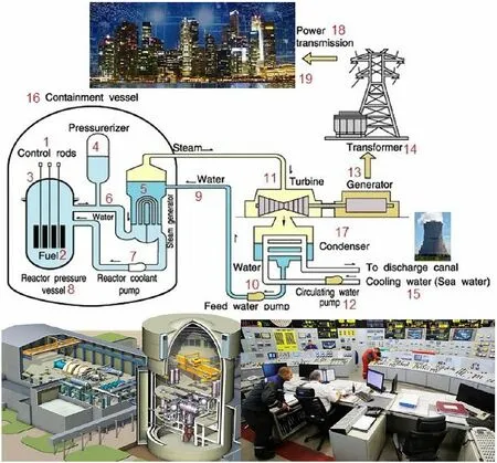
Fig.1 Typical pressurized water reactor PWR-VVER 1200 MW.(Color figure online)
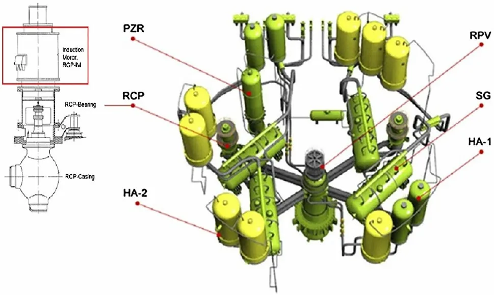
Fig.2 VVER-1200/V392M nuclear steam supply system.(Color figure online)

Fig.3 Reactor core with control rod banks (The arrows denote the nominal positions of the inlet nozzles.(Color figure online)
Fault diagnosis systems and intelligent RCP controls are essential for operational safety and accident management.The primary objective of implementing AI techniques is to ensure stable control of the RCP to optimize its performance under normal conditions and maintain system safety even during abnormal incidents.This system bolsters reactor safety, even when dealing with a large influx of alarm signals that human operators might struggle to manage.Negative feelings, fatigue, stress, and personal conflicts can lead to disasters during the operation of complex systems such as nuclear reactors.During a nuclear accident, thousands of alarm lamps may flash in the first minute, potentially causing operators to lose concentration and become overwhelmed (as illustrated in Fig.1).Generally, computers can manage millions of multi-tasking and scheduling routines,while humans can manage a maximum of five tasks simultaneously.This discrepancy makes AI-based automation of nuclear reactors crucial [1, 2].
Additionally, in this study, a neural fault diagnosis system(NFDS) was implemented for identifying faults triggered by alarm signals in NPRs.The proposed method was applied to the detailed fault diagnosis of the NPR’s reactor coolant pump.In this research, the alarm data patterns and their corresponding faults of the Kori II nuclear reactor coolant pump were used to develop a fully automated, AI-based fault diagnosis system.Further details of this research can be found in [3, 4] and [5].
The rest of this paper is structured as follows: Sect.2 focuses on related studies on RCP Control and fault diagnosis.Section 3 presents the PWR-RCP Intelligent Control.Section 4 introduces the RCP- ANFIS fault diagnosis system.Finally, conclusions are presented in Sect.5.
2 Survey of related studies on RCP control
Several studies discussed many topics on RCP control.However, the topics have not been completely integrated.Some of these studies are discussed below.In 2021, Zhou et al.[6]presented the pressure pulsation performance of a diffuser in an RCP, which was analyzed by a digital simulation, and it was validated with experimental results.However, their study is valid only in the case of pressure pulsation.
Rodríguez-Prieto et al.[7] presented the effect of geometric factor Optimization on Coast-Down performance of RCPs.The stored energy at the moment of highest inertia of the RCP was employed to preserve the coolant service.Their study focuses on the hydraulic stability of the RCP.
In 2020, Ahmed et al.Hosan, Begum, Rahman, Razzaque, and Hasani [8] presented the effects of eccentricity on the hydrodynamic performance of RCP in different cavitation operations.Specifically, five schemes are realized by studying and optimizing structural schemes.They presented intensive research on RCP hydraulic characteristics that affect speed-pressure stability.
In 2021, Lei et al.[9] presented a digital adaptive fuzzy control technique to realize speed regulation for induction motors (IMs) with input saturation based on command filtering.They transformed the analysis into a discrete-time form using the Euler formula, which is a special case.
Jirasuwankul [10] presented fuzzy Direct Torque Control (DTC) for an induction motor derived from a two-level electronic inverter.The main objective was to enhance the system characteristics by eliminating stator flux ripples and electromagnetic torque while enhancing stator current pattern.The study was mainly dedicated to the inverter design.
In 2019, Wang et al.[11] presented a technique for enhancing the energy efficiency of an induction motor driven under high-temperature conditions, which could be valid in high-temperature reactors.
In 2014, Morten Lind and Xinxin Zhang [12] presented a fault diagnosis method that could be explained by the consequent actions of fault recognition, location, and classification.They avoided the physical properties and control systems of the RCP.
In 2017, Lew, Ulrich, Boring, and Werner [13] presented a two-stage digital twin-assisted fault diagnosis technique,using deep learning (DFDD), that implements fault recognition in the agile development, operation, and maintenance stages.The agile development discussed in their study may not be appropriate for nuclear systems.
In 2021, Ribeiro et al.[14] presented a rotating-machinery fault diagnosis method that plays an important role in the industrial field.This study differs from the studies on the benefits of employing AI in fault diagnosis.
Chandrasekaran, Durairaj, and Padmavathi [15] presented a method called command-filtered fault-tolerant control(CFFTC), which was investigated for induction motors (IMs)digital control of induction motors in the case of actuator faults and anonymous load fluctuations.In the study, they neglected the IM and RCP interaction dynamics.
3 PWR-RCP adaptive fuzzy control
The RCP is a crucial component of a nuclear steam supply system (NSSS) in the design of pressurized water reactors(PWRs).The RCP propels the coolant through the reactor core and primary cycle in a PWR, while in a boiling water reactor (BWR), it pushes the coolant through a steam generator to maintain a thermodynamic equilibrium in the cooling cycle.The RCP’s operational conditions significantly affect the coolant’s mass flow rate and core’s thermal behavior.For instance, in accident management scenarios involving power supply loss, the RCP ensures coolant circulation during the coast-down, allowing for a smooth transition to the natural circulation mode [16].
The PWR incorporates two concurrent light-water circuits, as depicted in Fig.1.The stability of the chain reaction is ensured by a reactor control and protection system (1).The primary circuit (6) includes water heated by nuclear fuel rods (2) to a maximum of 239.7◦C within the reactor pressure vessel (8).This water from the primary circuit is ejected from the steam generator (SG) tubes and then pumped back into the reactor via the primary reactor coolant pump (3, 8).All equipment in the primary circuit is located within a containment building (16).Due to a high pressure of 17.6 MPa,water within the primary circuit remains liquid.After being heated in the reactor, this water then proceeds to the steam generator (13) placed within large cylinders with internal tubes.The VVER-1200 SGs are horizontally positioned per reactor island to further enhance safety measures.The primary circuit water is directed to high-pressure tubes, while the secondary circuit water (9) is pumped into the steam generator by the feed water pump (10).The pressure in the secondary circuit is about half of that in the primary circuit,which allows the secondary circuit water to vaporize and absorb heat from the vessel tubes within the SGs.The steam produced is then transferred to the turbine (11), which is subsequently set in motion.This rotation drives the generator, resulting in the generation of electricity, which is then transferred to a switchyard (14).As the steam flows through the turbine, it cools and condenses into a hot liquid.This liquid must be further cooled before it is returned to the steam generator.This cooling is achieved either in a cooling tower(15) or cooling pond.Subsequently, the circulating water pump (12) returns the water to the secondary circuit.Finally,power transmission (18) delivers the generated power to the public, as illustrated in Fig.1.
3.1 VVER 1200 reactor coolant pump adaptive fuzzy control
VVER-1200 represents the latest generation of VVER reactors.VVER is an acronym for Vodo-Vodyanoi Energetichesky Reaktor (Russian), which translates to an English water energetic reactor [6].The primary coolant cycle absorbs heat from the NPR core and conveys it to the secondary cooling cycle.To avert the vaporization of the primary cycle coolant under high temperatures, coolant pressure is sustained at 155 bar using a pressurizer [1].Hence, any leakage in the primary coolant system, also known as the reactor coolant system, would lead to a significant loss of reactor coolant.A substantial coolant loss in the primary circuit can trigger abnormal core heat-up [17, 18].The reactor operates with four loops at nominal power.However, at reduced power levels of 67% , 50% , and 40% , the reactor employs three loops, two opposite loops, and two adjacent loops,respectively.
The VVER-1200 reactor is an evolution of the VVER-1000 reactor.VVER- 1200 and NSSS were designed by Gidro Press to improve the performance and safety of the reactor.The design of VVER-1200 is based on several reactor-years of experience during the operation of the VVER[19].Two distinct versions of VVER-1200 exist, namely VVER-1200/V491 and VVER-1200/V392M, as illustrated in Fig.(2).These designs, developed by JSC SPb AEP in St.Petersburg and JSC Atom Energo Proekt in Moscow, differ primarily in terms of their safety systems.For instance, the VVER-1200/V392M design incorporates a two-stage safety system.
An increase in the RPV dimensions provides an essential decrease in the radiation impact on the RPV wall [20]with heights from 10,897 mm to 11,185 mm, inner diameters from 4150 mm to 4250 mm, and wall thicknesses(core shell) from 192.5 mm to 197.5 mm.The fuel length changes from 3530 mm to 3730 mm such that the reactor power increases, while the total number of fuel assemblies(FA) in the reactor core remains unchanged (163 FAs), as shown in Fig.3.
The initial steady-state conditions of the plant are as follows:
• Reactor Power: 100% RC.
• Pressure: 155 Bar Core Average.
• Temperature: 306.9◦C.
• Time in Life: BOC (Beginning of Cycle).
• SG Pressure: 70 Bar.
The control of the reactor is supplemented by preventive emergency protection systems [21].These systems signal a control protection system (CPS), which leverages control rods and drives to reduce power or prevent a power surge,thereby avoiding reactor shutdowns and violations of safety limits and standard operating conditions.The fast power setback (FPS) system automatically lowers reactor power through the insertion of automatic control banks by Power Setback-1 (PS-1), and it prevents an increase in reactor power by inhibiting the withdrawal of the CPS rods.Figure 2 depicts the flow rate and rotational speed of RCP-1391 in the VVER-1200 NPP, which is one of the four functioning RCPs.
During both normal operation and transient states, the control rod banks move within their control range to maintain the power distribution within specified limits.Axial offset (AO) is defined as the disparity between the power density in the upper and lower sections of the core, relative to the current reactor power.An AO value exceeding the recommended range can lead to non-uniformity of the neutron flux and axial xenon oscillations.The presence of these oscillations can adversely affect the time required for reactor stabilization.Under certain operational conditions, the non-uniformity of the neutron flux within the reactor system can induce transient states.Therefore, to ensure safe and efficient reactor operation, it is crucial to minimize the deviation in AO, particularly when the reactor power reaches or exceeds 80% of the rated power.The variations in AO under these conditions, and the respective limits for the VVER-1200 reactor, are presented in Figs.2 and 3, respectively.A deviation of approximately ±0.2% is considered acceptable when compared to the recommended±5% (Fig.4).
A strong correlation between practical and simulated results suggests that the thermal-hydraulic characteristics and control protection system are accurately modeled within the simulation.The validation process in real-time showed that the drop time of the control rod banks fell within the range stipulated by the design.Consequently, it is anticipated that the implementation of intelligent control systems will be robust and effective,offering enhanced analysis of operational processes and safety systems in recent VVER-1200 nuclear reactors, and thereby furthering research and development efforts.
3.2 PWR VVER-1200 RCP dynamic analysis
Based on the principles of RCP mechanics and dynamics, both the driving power and energy necessary can be assessed to ensure RCP operation.
3.2.1 Induction motor flux observer
The dynamic model of the PWR-RCP induction motor can be represented by thed-andq-axis components in a synchronous rotating frame.

Fig.4 Typical structure of RCP induction motor speed control.(Color figure online)
If the stator flux is constant, then the electromagnetic torque can be controlled only by theq-axis current.
3.2.2 Speed and stator resistance adaptive rotor flux observers
Considering linear magnetic circuits, equal mutual inductance,and neglecting iron losses, if the stator currents and rotor flux are selected as the state variables, then the state equations can be expressed in a stationary reference frame.
where the input states are the stator current and angular rotation, the output state is the speed in Eqs.(7), and (8) provides the relation between the speed and torque.
The electromagnetic torque developed by the RCP induction motor is expressed in terms of rotor flux and stator currents as follows:
The load torque acts as a disturbance according to the following mechanical equation:
Specifically,mIdenotes rotor inertia,pdenotes the number of pole pairs, andTLdenotes load torque.To obtain the estimated stator current and rotor flux mainly using the measured stator current→isand stator voltage→vs, the following equations can be used.
where "e" denotes the estimated values,Ldenotes the feedback gain matrix of the Luenberger observer, ande(t)denotes the stator current observation errors.
In Fig.5, the motor speed output is fed back to be subtracted from the reference signal.The resulting output is then sent to the input of the fuzzy controller, which comprises three stages: fuzzification, inference rules, and defuzzification.The output of the fuzzy controller is then driven to the power electronics stage, which generates three-phase control signals.These signals are used to feed the induction motor across the three phases (A, B, and C).
The architecture of the fuzzy-logic controller consists of the following stages, as depicted in Fig.6.
Fuzzifier: This stage transforms the precise inputs into fuzzy sets.Normalized fuzzy sets are delivered to the fuzzy logic controller, where they undergo conditional processing.
Inference Rules: This stage deploys optimal rules for a specific input.It then uses these rules on the precise input data and produces a fuzzy output.The decision-making within the fuzzy logic control system is guided by these rules and membership functions.This stage also includes IF–THEN logical conditions used for conditional logic processing and control system operation, as depicted in Fig.6.
Defuzzifier: This stage transforms the fuzzy data sets back into precise output.Defuzzification is the final stage of the fuzzy logic system and is sometimes referred to as denormalization.
Figures 7, 8, 9, and 10 demonstrate that the motor speed,motor torque, and current realized a steady-state value in roughly 150 ms, which is significantly commendable.The average values of the fluctuations reached acceptable thresholds, thereby ensuring the stability of the entire control system.

Fig.5 PWR-RCP induction motor adaptive fuzzy control system.(Color figure online)

Fig.6 Three phases of the fuzzy logic controller of the PWR-RCP.(Color figure online)

Fig.7 PWR-RCP induction motor speed.(Color figure online)

Fig.8 PWR-RCP induction motor torque.(Color figure online)
Numerical simulations are conducted on the RCP propelled, as depicted in Fig.5, utilizing a PWR-RCP induction motor drive.The aim of these simulations was to evaluate the effectiveness and dynamic performance of the proposed adaptive fuzzy control.Figure 5 outlines the comprehensive configuration of the adaptive scheme and illustrates the consideration of RCP dynamics.An operation cycle is a set of data points that represent RCP speed over time.It is characterized by a low RCP speed and is beneficial for evaluating RCP performance across all operating modes.

Fig.9 Torque speed relationship.(Color figure online)
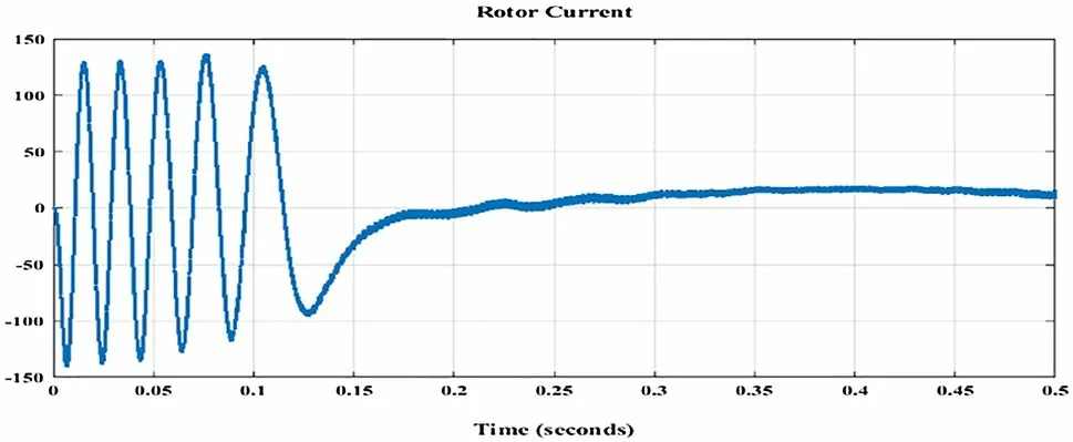
Fig.10 Rotor current.(Color figure online)
For the purpose of adaptive control, an estimator scheme for rotor speed, torque, and flux was proposed, which is based on a fourth-order electrical model.The performance of the adaptive fuzzy strategy is displayed in Fig.5.The speed is shown in Fig.7, the torques in Fig.8, the torque–speed relationship in Fig.9, and the rotor current in Fig.10.These graphs illustrate the changes in acceleration status and reactor power profiles.Notably, the variations in speed and torque are as substantial as those in the operation mode profile.The results indicate that the proposed strategy operates satisfactorily.
4 PWR-RCP NFDS-based alarming and fault diagnosis system
NPRs are extensive and complex systems.To enhance plant safety, operator support systems, such as NFDS-assisted alarm and fault diagnosis systems, have become increasingly important.Various key recommendations have been proposed, one of which includes the passive safety of nuclear reactors.Additionally, comprehensive research on the application of AI techniques for nuclear reactors has been presented in [22, 23].
4.1 Reactor’s safety based on artificial intelligence(AI)
An alarm and fault diagnosis system can be designed based on the statistical model analysis of nuclear reactor operating conditions, which reflect the normal operation of the NPR.However, implementing a nonlinear fault diagnosis system based on statistical analysis can be especially challenging due to inaccuracies in the statistical model and unforeseen disturbances.Consequently, there is a trade-offbetween the false alarm rate and the missed detection rate.
Once a diagnosis is established, recovery procedures can be implemented, leading to what is referred to as fault-tolerant control.In complex processes, acquiring an accurate analytical model can take years, necessitating the use of other diagnostic methods based on new types of models.Digital signal processing serves as another method for fault diagnosis when an analytical model is not available.Signals can be analyzed using various methods, such as time-domain methods, spatial-domain data models, frequency-domain methods, or more sophisticated methods like wavelet analysis.These methods aim to ensure that a change in certain quantities is characteristic of a specific fault [24, 25].
AI-based fault diagnostic systems have been extensively studied to assist NPR operations under abnormal conditions.The primary objectives of these systems are alarm detection and fault diagnosis.A fault signifies a deviation from the expected system performance, and alarm signals are examined in a real-time case study.Fault recognition involves generating symptoms from fault indicators and determining the time of recognition.It identifies the type and location of a key fault from a set of alarms, linking it to a physical component that exhibits inconsistent performance.Although it is evident that diagnosis is crucial, real-world applications of these systems continue to be utilized [6, 11].
An AI-based classification or pattern recognition approach is utilized for fault diagnosis, relying on system data or expert knowledge of the NPR.Relevant alarms are identified as representative of each type of failure.The relationships between alarms and faults are established using a supervised learning approach when the faults are known a priori, such as those in an expert system.In this scenario, the system’s fault recognition is adjusted to match the correct answer from a training set of known faults.A fault diagnostic system serves as a classifier that, in real time, must identify the actual condition represented by new alarm data and associate it with one of the known faults.A recognition system might also employ online machine learning to handle unknown faults [11, 16].
4.2 Proposed neutral fault diagnosis approach
In diagnostic applications, faults are characterized by their associated alarms, which evolve over time and follow a trajectory within a space of observed variables.The stages of the neural fault diagnosis system (NFDS) are distributed throughout the entirety of NPR and are closely connected to alarm and fault diagnosis systems.Each unit of the NPR possesses its own diagnostic system.The overall plant features a comprehensive alarm and fault diagnosis system that integrates all the individual subsystems.Given that the plant’s control system can be evaluated by the NFDS for fault detection, all units of the plant can be tested using NFDS techniques.
4.2.1 AI-based fault diagnosis of the RCP
Kori Nuclear Power Plant is a South Korean NPR located in Kori, a suburban village in Busan.Since 2016, it has been the world’s largest fully operational nuclear power station in terms of total reactor count and number of currently operational NPRs, surpassing Canada’s Bruce Nuclear Generating Station in nameplate capacity.The plant is owned and operated by Korea Hydro & Nuclear Power, a subsidiary of KEPCO.The station’s first reactor commenced commercial operation in 1978 and continued until 2017 when it was decommissioned.Units 2, 3, and 4 initiated commercial operations in the 1980s.All reactors at the site are pressurized water reactors (PWR).Kori-2, the second unit of the Kori Power Station, is a PWR with the technical details provided in Table 1.A neural fault recognition tool in MATLAB is used to establish the neural network.It consists of 12 input nodes, 10 hidden nodes, and nine output nodes, as depicted in Fig.11, Tables 2, and 3.
Different designs with varying numbers of hidden nodes have been tested.However, these are associated with errors.Our testing confirmed that using 10 hidden nodes provides a more accurate design with an acceptable margin of error.In the case of the error backpropagation training algorithm (EBPTA)depicted in Fig.12, the weights of the NFDS are adjusted until the RMS error reaches its optimal learning value, at which point the learning halts [26].The proposed technique can be applied to all global fault diagnosis systems at every critical point within a NPP.
In accordance with each training pattern, the hidden layer nodes generate their own outputs, which serve as inputs for the output layer nodes (see Fig.11).As the learning process progresses, the RMS error diminishes until the allowable error is achieved, which subsequently halts the training.After network training, each data pattern acquires its own error value, referred to as a pattern error.

Table 1 Technical details of Kori-2, the second unit of the Kori Power Station
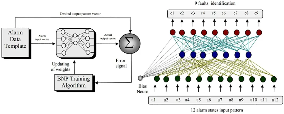
Fig.11 PWR-RCP flowchart of the proposed NFDS adaptive fault diagnosis system.(Color figure online)
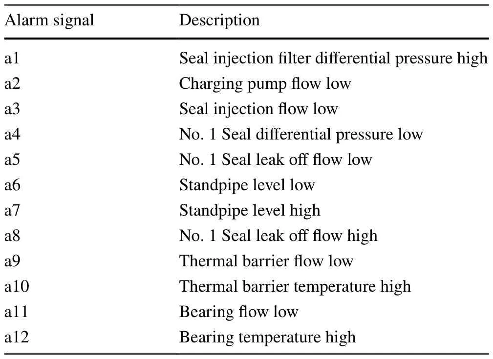
Table 2 Kori-2-RCP, Alarming signals definitions
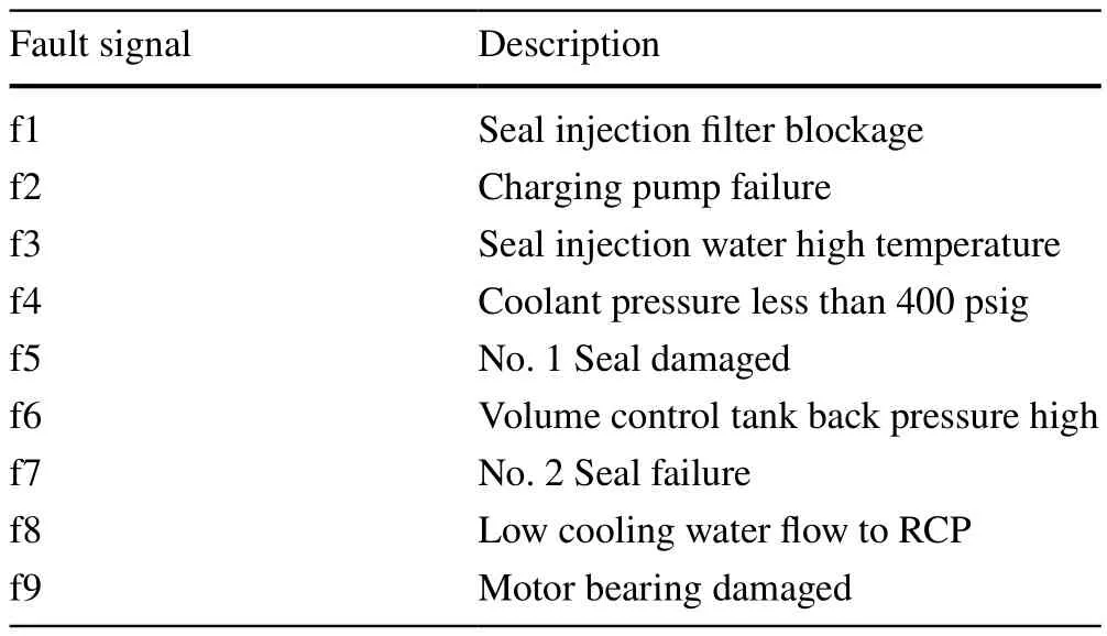
Table 3 Kori-2-RCP, Alarming signals definitions
4.2.2 EBPTA Local minima

Fig.12 The standard error backpropagation training algorithm(EBPTA).(Color figure online)
The error backpropagation training algorithm (EBPTA)may encounter the issue of local minima, potentially resulting in slow convergence learning.This problem arises from the neuron output saturation of the hidden layer (see Fig.12).EBPTA is the standard learning algorithm of multi-layer neural networks, with varying details across different topologies.EBPTA is among the most renowned machine learning algorithms, joining the ranks of maximum likelihood, nearest neighborhood, matrix inverse lemma, Wiener filter, Kalman filter, least mean square (LMS), recursive least square (RLS), and heuristic optimization.Its operation primarily depends on minimizing the error between the model machines and the actual systems.
In this study, each training pattern employs a unique activation function for every neuron in the hidden layer.This function can be adapted by adjusting the gain parameters, alongside the modulation of the momentum and learning rate of the learning algorithm.A weight update was performed as follows:
whererdenotes the learning signal andWdenotes the weight vector.Furthermore,Xdenotes the net input,ddenotes the desired output, andcdenotes a learning speed constant.The error function was calculated using Eq.12:
Specifically,Edenotes the error at iterationk,ddenotes the desired output, andodenotes the real output as shown in Fig.(13).The gradual error decrement in Fig.13 indicates the success of the training process.
The momentum can be calculated using the following equation:
Figure 14 shows identical outputs for the real and simulation signals.
4.2.3 Validation case of study for the NFDS
In NPPs, every module within the control and operation system adheres to rigorous validation rules.These are designed to test and ensure the module’s adequacy for the targeted mission.We ascertained the efficiency of the application by examining the network learning results.The effectiveness of the applied NFDS was tested by invoking input patterns along with their corresponding weight patterns [27].The evoked fault diagnosis patterns were employed in inverse calculations to identify the fault type.These results were then compared with the original fault alarm map for validation.To verify the accuracy of the fault diagnosis system,samples of selected alarms/faults were used.The design of the fault diagnosis validation network is shown in Fig.15 with two layers for input/output consisting of 4/3 nodes [28,29].

Fig.13 Smooth decrement of error during learning.(Color figure online)
The input patterns (a1, a2, a3, and a4) were samples drawn from the alarm patterns, and the output patterns(O1, O2, and O3) represented the corresponding faults of the input pattern.Both the alarms and faults are defined in Table 4 and Fig.15.
Using 3920 iterations of learning the designed network,good patterns become 100% , and the learned network can now estimate any fault according to its alarm pattern.The learning parameters used in the network learning process are listed in Table 4.After 3920 learning iterations, the NFDS modifies its weights to minimize its RMS error value, which reaches the targeted RMS error (0.001) and is considered the main parameter of the neural network fault diagnosis system.
Following the learning process, the attributes of the NFDS were evaluated.The functioning of the NFDS can be confirmed by invoking input alarms and computing the network output faults based on the acquired weights.A comparison between the NFDS results and original fault map is displayed in Table 4.Three fault cases, O1, O2, and O3, are depicted in Fig.15.Further details on this research can be found in [3, 5].
5 Conclusion
In this study, an adaptive fuzzy control system was implemented to manage the RCP of the reactor, enabling the pump to smoothly follow the reference signal.Additionally, the application of the NFDS was presented in the fault diagnosis NPRs.The NFDS approach showcased numerous advantages over conventional alarm processing methods, such as shorter knowledge acquisition time, lower development cost, rapid operational time, robustness against noisy alarm signals, and comprehensive mapping capabilities.The findings demonstrated that once the neural network was comprehensively trained using various known alarm patterns,it could accurately identify faults.Furthermore, even when presented with unknown or incomplete/sensor-failed alarm patterns, the network was still able to diagnose fault cases accurately.Multiple faults could also be diagnosed easily using a given alarm pattern.Thus, the study concluded that the NFDS approach is suitable for pattern recognition problems in environments abundant with noisy and real plant data.Moreover, NFDS-based systems exhibit the potential for swift operation, especially with available hardware implementations, making these systems particularly suitable for real-time applications such as alarm processing and fault diagnosis in NPRs.

Fig.14 Simulation results of the EBPTA.(Color figure online)
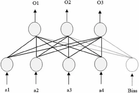
Fig.15 Structure of the fault diagnosis, case of study.(Color figure online)

Table 4 Kori-2, alarming/faults case of study
Author ContributionsAshraf Aboshosha and Hisham A.Hamad contributed to the study conception, writing, programming, material preparation, data collection, analysis, and design.They read and approved the final manuscript of the article.
FundingOpen access funding provided by The Science, Technology &Innovation Funding Authority (STDF) in cooperation with The Egyptian Knowledge Bank (EKB).
Declarations
Conflict of interestThe authors declare that they have no competing interests.
Open AccessThis article is licensed under a Creative Commons Attribution 4.0 International License, which permits use, sharing, adaptation, distribution and reproduction in any medium or format, as long as you give appropriate credit to the original author(s) and the source,provide a link to the Creative Commons licence, and indicate if changes were made.The images or other third party material in this article are included in the article’s Creative Commons licence, unless indicated otherwise in a credit line to the material.If material is not included in the article’s Creative Commons licence and your intended use is not permitted by statutory regulation or exceeds the permitted use, you will need to obtain permission directly from the copyright holder.To view a copy of this licence, visit http://creativecommons.org/licenses/by/4.0/.
杂志排行
Nuclear Science and Techniques的其它文章
- Dynamic scaling characteristics of single-phase natural circulation based on different strain transformations
- Comparison between 4D robust optimization methods for carbon-ion treatment planning
- Aperture shape optimization in intensity-modulated radiation therapy planning
- Calculation of microscopic nuclear level densities based on covariant density functional theory
- Discrimination of pp solar neutrinos and 14C double pile-up events in a large-scale LS detector
- EJUSTCO: Monte Carlo radiation transport code hybrid with ANN model for gamma-ray shielding simulation
