Phase transition in bilayer quantum Hall system with opposite magnetic field
2023-10-11KeYang杨珂
Ke Yang(杨珂)
Kavli Institute for Theoretical Sciences,University of Chinese Academy of Sciences,Beijing 100190,China
Keywords: fractional quantum Hall effect, bilayer quantum Hall system, opposite magnetic field, quantum phase transition
1.Introduction
Since the discovery of the quantum Hall effect (QHE),the interesting phenomenon has attracted long-lasting theoretical and experimental interest from researchers.[1]The quantum Hall(QH)state introduced the concept of topological order.The quantization of the Hall conductance is considered equivalent to a topological invariant.[2]The topological phase can be applied to both insulators and superconductors when an energy gap is active between the ground state and the excited states.The topological invariant as a topological order characterizes the nature of the topological state.[3]A filled band is equivalent to a filled Landau level and the Hall conductance is equivalent to the Chern number of a band as a topological invariant.[4]Topological phase in topological insulators can be characterized by Chern numbers of bands,and correlated states can be as an analogy of fractional quantum Hall(FQH)states induced by strong interaction.[5,6]In this paper we address the system in terms of multi-component FQH states as a fractional-quantum-Hall-like(FQHL)system.FQH effect has been extensively studied and people have a good understanding of various FQH states.After realizing particular FQH states in mapped bilayer quantum Hall system, we use numerical results from exact diagonalization (ED) and theoretical tools for FQH to understand the topological phases of the FQHL system.
The bilayer quantum Hall system(BQHS)has served as a platform for the research of strongly correlated physical phenomena induced by Coulomb interactions under large magnetic fields.[7–9]A bilayer system is established by two parallel layers of two-dimensional electron gas (2DEG) separated by a distanced/lB(measured in units of the magnetic lengthlB).Various quantum Hall (QH) states could be realized by tuning system parameters such as the scales of Coulomb interaction,the tunneling interaction and the Zeeman energy.[10–16]Typically, varying the separationd/lBwill lead to competition between intralayer interaction and interlayer interaction.The interlayer Coulomb interactions introduce the interlayer coherence until the separationdgoes large enough.Phase transitions are driven during the two coupled 2DEG going decouple.[7,17]
The phases can be described as an exciton condensate of paired particles.[7,8,17–19]The picture is under a Landau quantization:the energy of 2DEG is quantized as the Landau levels(LL)within a perpendicular magnetic fieldB.The filling factorνat the lowest Landau levels(LLL)is defined as the radioν=Ne/Ns, thatNeis the number of electrons andNsis the number of magnetic flux quanta through the area.A pseudospin analogy[20]is usually introduced: the index of layer plays a role as spin.The upper layer is labeled as↑and the other is labeled as↓.The BQHS is then defined as a twocomponent fractional quantum Hall system.[21]The excitons are usually interpreted as electron–hole pairs.Electrons of one layer are bound to holes of the other layer.
The phases described by excitons of a small-separated and balanced filling bilayer system atνt=1 display the quantum Hall effect(QHE).[8,22]A quantized plateau of Hall conductance can be observed and the charged excitations have an energy gap.When separationd/lB →0, the BQHS is reduced to a two-component monolayer quantum Hall system whose ground state is well known as the Halperin (111)state.[23]As the layer separation is increased, the exciton superfluid (SF) will vanish at a large enough critical separationd/lB.As a result of decoupled layers,the system enters a compressible phase that can be described as composite Fermi liquid(CFL).[24]The closing of charge gap and vanishing quantized plateau of Hall conductance indicate the disappearance of QHE.The phase transition from exciton SF to CFL has been widely studied theoretically and experimentally.[25–33]
FQHE was also observed at total fillingνt= 1/2 in quantum well systems.[10,12,13,15]The states could be realized in a mapped two-component BQHS.[12,15]In limits of the separationd →0 andd →∞, the ground states of bilayer could be viewed as CFL.In the intermediate regime,the quantized plateau of Hall conductance and energy gap can be observed.[12]The ground states without interlayer tunneling are confirmed as the Halperin (331) state by numerical evidences.[15,34,35]The paired state can be viewed as a pair of composite fermions.When the interlayer tunneling is nonzero, a new phase transition from Abelian Halperin(331)state to non-Abelian Moore–Read Pfaffian state has been observed.[36,37]With various tunable parameters, new phase transitions[38,39]have been realized and analogous multicomponent quantum Hall states filled in interacting particles(Fermions or Bosons[40,41])have been observed atνt=2/3[16]andνt=1/4.[11]Compared to the one-component FQH system,the extra degrees of freedom introduce more tunable parameters that may be the origin of exotic paired states.[21]Those fractionalized topological states observed in quantum well systems[10,12]and topological flat band models[4,5,42,43]can be mapped to be realized in the BQHS.
The BQHS has been a powerful platform to realize various FQH states.[44]Real spin and pseudospin lead to four component states in each LL.Multi-component states indicate a richer combination of filling factors.The interlayer interaction and the tunneling term are easily tunable to realize various interlayer coherent states.The BQHS is expected to provide richer and more exotic quantum phase diagrams.The BQHS can be artificially realized in the quantum well system and bilayer graphene system.Thanks to the development of technology,particles and holes can both be filled in each layer.More FQH states have been realized easily.[1,10,11,13,45–47]
The strongly correlated phases in the nearly flat band models have attracted lots of attention.These topological phases are characterized by a non-zero Chern numberCof the topological flatband.Recently the moiré superlattices of twodimensional materials are established as powerful platforms to realize the nearly flat band systems.[48]Superconducting states[49]and correlated insulating states[50]are observed in moiré superlattices of twisted bilayer graphene.In such systems,the Coulomb interaction is important and the valley can be viewed as a pseudo-spin,then strongly inter-valley correlations can drive phase transitions.Opposite Berry curvatures in two valleys were observed in super-lattices and then researchers proposed that bands in two valleys can have opposite Chern numbers.[48,51–53]These states are similar to states in Chern insulators.[48]The states with opposite Chern numbers in two bands can be viewed as particles in two LLs experiencing opposite magnetic fields while the real spin is frozen.[52,54]Then those FQHL states can be viewed as an analogy of the FQH states and then be realized in a particular BQHS.[55,56]
Motivated by the above considerations we prefer to use the BQHS as a powerful ideal model for realizing ideal proposals.We focus on the FQHL system with strong interaction.The topological phase transitions are numerically simulated by ED within a mapped BQHS.In this paper,we build a simplified model to study the phase transition of a FQHL system with Chern numbersC=±1 in two flatbands.In the mapped BQHS,particles in the mapped LLL of the two layers experience opposite magnetic fields.We focus on a balanced filling factor.No tunneling and the real spins are frozen.The separation distanced/lBis tuned to drive the new phase transition.The opposite magnetic field proposal could be further analogized as a BQHS with attractive interlayer interaction and repulsive innerlayer interaction under uniform magnetic fields.We perform exact diagonalization on torus geometry for the mapped BQHS.The paper is organized as follows.In Section 2 we will introduce the Hamiltonian of the mapped bilayer model and details of mapping are shown.In Section 3 we show the results from ED studies on the torus.The energy spectrum and the pair-correlation function are shown.In Section 4 we understand the phase transition in an effective field theory.A summary is given in Section 5.
2.Models and methods
The perpendicular magnetic field affects the cyclotron motion of a charged particle.Consider electrons moving in a 2D plane that experience a uniform perpendicular magnetic field.The single-particle Hamiltonian is described as
where we take Landau gauge with theBdependent vector potentialAξ(r)=-ξB(0,x,0).We defineξ=±1 forBz=∓B,respectively.The commutation relation of the effective momentumπ=p+eAξ(r)is written as


The Hilbert space is limited to the lowest Landau level(n=0).A set of plane wavefunctions are useful in constructing the single-particle wavefunction.We setlB=1 for convenience.According to the conserved momentum inydirection,the conserved quantum numberkis important.We get a solution ofH0ψ(r)=Eψ(r)as
We take a transformationk=ξmto remake the relation in Eq.(4).We get the function
Herex=-kis the guiding center coordinate where the electrons are located at.The labelξis defined in theydirection, with useful relationThis wavefunction describes a plane wave propagating inywith momentumξ¯hk.
To construct many-particle states we take the torus geometry whereLx×Ly=2πNs.Nsis the total magnetic flux towards the unit area and the orbital numberwithnk=0,1,...,Ns-1 according to the periodical boundary conditions.The wavefunctions described in Eq.(5)could be considered as single-particle wavefunctions located at sitek.To create a particle at positionr,we use the fermionic field operators
where the fermion operatorsare defined in LLL of orbitalkwith spinσunder flux indexξ.These operators satisfy the canonical anti-commutation relations


The part of the constant energy will be discarded.From the above derivation, we find thatξcould also be considered as the charge of particles.The transform from ‘+’ flux to ‘-’flux is equivalent to a particle–hole transform.When considering the two-body interactions,the differences between these two Hamiltonians will be discussed in Appendix B.
Consider the Coulomb interaction between particles.The total Hamiltonian isH=HT+Hint,where the kinetic termHTis constant that will be omitted due to strong interaction.According to the pseudospin analogy,↑labels one layer and↓labels the other.Electrons are filled in each layer, we haveν=ν↑+ν↓.For convenience, we setξ=1 whenσ=↑andξ=-1 whenσ=↓.The indexξis related toσ.The twobody Coulomb interaction HamiltonianHintis defined as

In the above equations we have transformed the density operator so that the two particles are under uniform magnetic field.The only effect is a negative sign which could be combined into electronic potential termVσσ′(q).The repulsive interaction between electrons in different layers under opposite magnetic fields is equal to the attractive interaction between electrons in different layers under uniform magnetic fields.A mapped two-body Coulomb interaction Hamiltonian is written as
where

3.Numerical results
In this paper we have performed exact diagonalization(ED) calculations in a mapped quantum Hall bilayers system.In the mapped model,the intralayer interaction is repulsive and the interlayer interaction is attractive.We work on the torus and the ratioLy/Lxis unit.For a clear discussion,we address the lowest energy levelE0as ground state energyEgand then-th lowest energy level asEn.
In Fig.1 we show the low energy levels versus layer distanced/lB.We characterize the critical point atdc/lB~0.68.When distanced/lBincreases acrossdc/lB,we can observe a significant collapse of degeneracy and the energy levels crossing.The characteristics indicate a critical point.When distanced/lBcontinues increasing, several low-energy excited states decay exponentially to the energy levels of the ground state.
In the region ofd/lB <dc/lB,the states in each level are highly degenerate.In Fig.3(a),we show the highly degenerate states at differentksectors ofd/lB=0.The ground states forNe=18 are 20-fold degenerate,as shown in Fig.1(a).The degenerate states are at sectorkx=0 orky=0.The black circle in Fig.3(a) shows the degeneracy for the first excited energy levels.The first excited states forNe=18 are also 20-fold,which are at sectorkx=1 orky=1.According to symmetry,we focus on sectorki ∈[0,π],(i=x,y).We summarize that the degeneracy of states is(Ne+2)-fold.The details of highly degenerate states are slightly different forNe/2= odd/even.ForNe/2=odd,the degenerate states are at sectorskx=0 andky=0 while forNe/2=even the degenerate states are at sectorskx=πandky=π.We take the system forNe=16 as an example.The numerical results are shown in Fig.1(b).
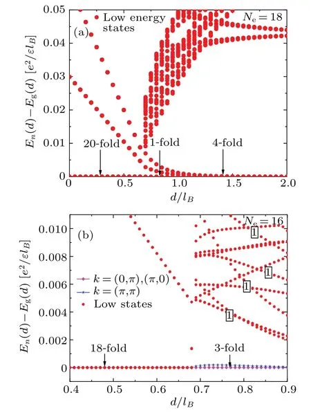
Fig.1.The low energy levels as a function of layer separation d/lB.We characterize dc/lB =0.68 as a critical point according to the collapse of degeneracy.We show the high degenerate states in each branch in d/lB <dc/lB.(a) The spectrum is for Ne =18.In the region d <dc, the states are 20-fold at ground states and the first excited states.The degeneracy is removed when d goes larger across dc.The lowest-energy state at d/lB →dc/lB limit is 1-fold.The three excited energy levels decrease to~10-4 with growing d/lB.The lowest-energy states are 4-fold at large d limit.(b) The spectrum is for Ne =16.The states are 18-fold at ground states and the first excited states when d <dc.The lowest-energy state at d/lB →dc/lB limit seems 3-fold.There are numbers of extra energy levels that are exponentially decaying to the level of ground states with growing d/lB.These levels are labeled by‘1’in(b).
When increasingd/lBpasses throughdc/lB,the degenerate states in each level are removed.Energy level crossing is shown in Fig.2(a).We show results of energy levels at variousksectors as a function ofd/lB.We plotted curves at the representativeksectors.The lowest energy level ofk=(π,π)remains at the energy-level scale of ground state.The ground energy level ofk=(0,6·)jumps from the energy level of ground state and continues increasing with increasingd/lB.The ground energy level ofk=(0,π) jumps from the level of ground state and then continues decreasing exponentially to the level scale of ground state.The ground energy level ofk=(π,π)falls sharply and continues decreasing exponentially to the level scale of ground state too.The discontinuous curves of energy levels indicate a critical point.The first-order derivative curves of the ground-state energy as a function of distanced/lBare shown in Fig.2(b).The curves for different system sizes exhibit a discontinuous behavior,which indicates a first order phase transition.The critical point can be confirmed atdc/lB=0.68.
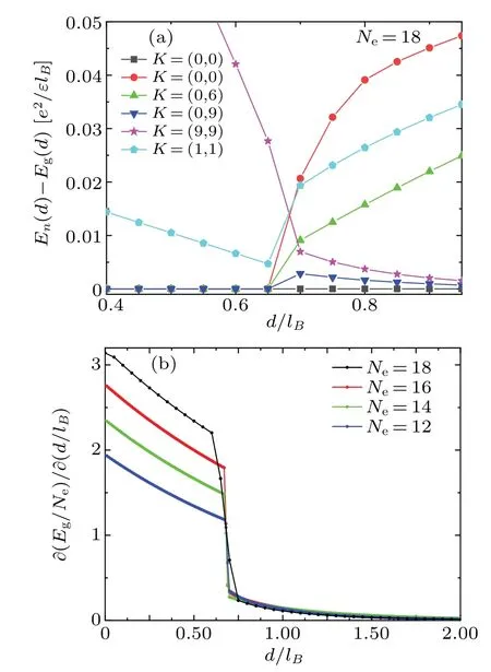
Fig.2.Numerical evidence for the critical point.(a)The low energy levels of a function are plotted against layer separation d/lB at different K sectors for Ne =18.We show the energy level crossings between different K sectors at dc/lB.We set k= (b) The frist-order derivative curves of the ground-state energy Eg/Ne as a function of layer separation d/lB.
In Fig.3 we study the energy gaps between the excited states and the ground states as a function ofk.The blue line in Fig.3(a) represents a nearly linear behavior.The energy levels of the selected points in the blue line are related to the energy levels of ground state at sectorky=kx.We measure the gaps between the excited states and ground states shown in Fig.1(a) with the help of ground levels atky=kxsector shown in Fig.3(a).The nearly linear relation is plotted in Fig.3(c)as a function of|k|.The relation can be summarized as ΔEn=Eg(k=(n,n))-Eg∝|k=(n,n)|.ΔEnis the gap between then-th excited levelsEnand the ground levelsEgshown in Fig.1(a).AndEg(k) is the lowest energy level atksector.As shown in Fig.1(a), the gaps reduce with the increase of distanced/lBin the region ofd <dc.We show the energy gaps as a function of|k|atd/lB=0.7 in Fig.3(b).As entering a new phase,the nearly linear relation is vanishing.
The system enters a new phase in the region ofd/lB >dc/lB.We divide the whole region into two limits.Depending on the scale of separationd/lB,we address one asdclimit and the other as largedlimit.We argue if the states of the two limits are in one uniform phase.

Fig.3.Energy gaps as a function of k at d/lB =0,1.0 for Ne =18.(a)We show the energy gaps for k=(kx,ky)at d/lB =0. En(kx,ky)=En(ky,kx) is considered.The x-axis is defined as kx+11ky.The blue line shows the nearly linear behavior of the levels of kx=ky sector.The black circle shows the degenerate states in the first excited level.(b)We show the energy gaps as a function of|k|at d/lB=0.7.(c)The nearly linear behavior of the ground levels as a function of|k|at kx=ky sector.
At the limit ofd/lB →dc/lB,the state of the lowest level is atk=(0,0)forNe=18 andNe=14.According to Fig.1(a),we find the ground state ofk=(0,0) to be at the ground energy level.We address those as “fixed ground level”.Three energy levels at sectork=(0,π),(π,0) and (π,π) decay exponentially to the ground level asd/lBincreases when the degeneracy is removed,as shown in Fig.2(a).We address those as “decreasing ground level”.We also identify energy levels that increase with increasingd/lB.Energy gaps of increasing states will reach a stable level at larged/lB.We address those as “increasing excited level”.The states of the fixed ground level should be described as 2-fold states atk=(0,π),(π,0)forNe=16 andNe=12 in the region of intermediated.The results forNe=16 shown in Fig.1(b) raise an problem.Ford/lB=0.7>dc/lBthe gap is at scale of~10-4betweenEg(k)ofk=(π,0),which is the ground state,andEg(k)ofk=(π,π)which is considered as a higher excited state.The gap energy level of ground state atk=(π,π)exhibits an exponential decaying behavior versus increasingd/lB, so we think that the ground state ofk=(π,π)should be referred to as“decreasing ground level”.In Fig.1(b),we find more exponential decaying energy levels with increasingd/lBwhich are labeled as “1”.They will keep decreasing to the ground level or the excited levels at largedlimit.The high-energy levels that fall to excited levels at largedlimit are summarized as“decreasing excited level”.We have summarized the above behaviors in the region of intermediated.The states of ”fixed ground level”and “decreasing ground level” can be considered as ground states.Whend/lBis large enough,the energy levels of the corresponding states come to the scale of ground level.The same picture forNe=16 could be observed forNe<18.The extra decreasing levels that decrease to the ground level at largedare viewed as noises forNe<18.The picture forNe=18 is the ideal, as shown in Fig.1(a).We speculate that the noises in the picture shown in Fig.1(b)as an example come from the finite size effect.The summarized behaviors are valid for all the system sizes we used.
We consider the two layers to be completely decoupled at largedlimit.The degeneracy of ground states increases with the low excited states decaying to the scale of ground states.In Fig.4, we show the gaps ΔE(ky) between the ground states of differentkysectors atd/lB= 0.7, 1.0 and 1.2 forNe= 18.The falling of the ground energy level atky=πcould be observed.The energy dispersions settle into a mirror symmetrical structure atd/lB >1.The symmetric center is atky=π/2 and the relation could be expressed asEn(ky)=En(π-ky),(ky ∈[0,π]).The similar results forNe=16 are shown in Fig.5.Atd/lB=0.8,the energy dispersions are complicated according to the energy spectrum shown in Fig.1(b).As previously argued,the scales of these energy levels are close.It is difficult to determine a clear energy gap.We considerEg(k) ofk= (π,π) to be in the ground level.Compared to results in Fig.4(a), the gap level Δ~Eof sectorky=π/2 is at the same scale.Atd/lB=1.8, the energy dispersions have a mirror symmetrical structure with the center atky=π/2.The decaying energy scale~0.01 has been observed.We consider the states under the red dotted line as ground states.These levels are‘decreasing ground level’.The blue dashed line identifies the scale of gap above the ground states which continue growing slowly with increasingd/lB.The mirror symmetrical structure and gap between ‘decreasing ground level’ and ‘increasing excited level’ are valid forNe=12 andNe=14.
We have reviewed features fordclimit and the largedlimit.There is no strong enough evidence to suggest that the two limits are in different phases.The summarized behaviors are applicable in the two limits.We observe a continuous transition.The crossover from thed →dclimit to the largedlimit is under uniform phase.
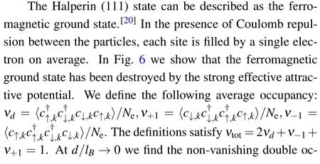

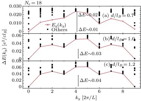
Fig.4.The low energy levels as a function of ky for Ne=18 at d/lB=0.7,1.0 and 1.2.The red crosses represent states of the lowest level at each ky sector,and the black squares represent the states of the second lowest level at each ky sector.The gap is considered as the difference between the lowest level and the next lower level.The energy scale of gap ΔE between the lowest excited states and the ground states is listed in each picture.
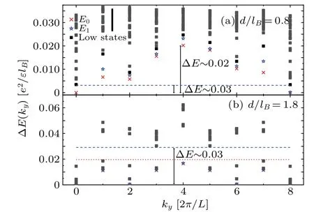
Fig.5.The low energy levels as a function of ky for Ne =16 at d/lB =0.8,1.8.The red crosses represent the lowest level of each ky sector,the blue stars represent the second lowest levels and the black squares represent the other low levels at each ky sector.We use blue dashed line to identify the scale of gap level.The states below the red dotted line are considered as degenerate ground states.The energy scale of gap between the lowest excited level and the ground level is listed in each picture.
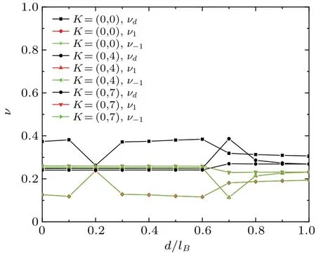
Fig.6.Average occupancy per site at ground state as a function of separation d/lB.The average occupancy at degenerate ground state is calculated for Ne =14 at K =(0,0),(0,4),(0,7) sectors.The results satisfy 2νd+ν-1+ν+1=1.

Fig.7.The pair correlation function gσ1,σ2(r) at ground state for Ne = 14.We use .(a) The interlayer pair correlation function g12(r) is shown as a function of separation d/lB.The inner figure shows results in degenerate K-sector and results for Ne=12.The results of main figure are calculated at K=(0,0)sector.(b)We show the interlayer correlation function g12(r)and the intralayer g11(r) correlation function at K =(0,0) sector.The separations are d/lB=0.0 <dc/lB and d/lB=0.9 >dc/lB.
The exciton superfluidity is well understood as a Bose–Einstein condensation (BEC) of paired-state via a particle–hole transformation in single layer.[63]Each pair is viewed as a bound state of two particles, described by an exciton wave function.[28]In a similar picture, we check the two-particle correlations to determine the order of the ground state.The interlayer pair correlation function is defined as
whereΦis the field operator andr=R1-R2.The intralayer pair correlation function is similarly defined asg11(r) =.Ind/lB <dc/lB, we calculateg12(r) in eachK-space at degenerate ground state.As illustrated in the inner figure of Fig.7(a), we can obtain an equal value ofg12(r) for each degenerateK-space.In comparison, the results ofd/lB= 1.2 show that lifting the degenerate ground state causes differences in theK-sector.We show the interlayer pair-correlation function at differentd/lBin the ground sectorK=(0,0) forNe=14 in Fig.7(a)and the intralayer pair-correlation function atd/lB=0,0.9 in Fig.7(b).In the regiond/lB <dc/lB, the peak ofg12(r) atr=0 and the vanishing ofg11(r=0) indicate an interlayer strongly correlated state.The intralayer pair-correlation function also has a peak atr~2.5.The observed peaks show strong short-range correlation.The spin-↑and spin-↓are filled at the same location.An exciton crystal is characterized in the fields of electron–hole plasmas[57]and the interacting bosonic gas.[58,59]The curves of pair correlation remain unchanged asd/lBvaries.In the regiond/lB >dc/lB,g12(r)approaches 1 asd/lBincreases,andg11(r)grows from 0 to 1 with increasingr.The features of pair-correlation function characterize a similar behavior described in the CFL limit.[64]
In Fig.8,we calculateg(r)in differentrxandryto clarify the spatial structure at the ground state.We find stripe correlations.The numerical studies for the stripe ground state at specific filling factorνin the lowest Landau level have been well understood in Refs.[25,60].The characteristics of the correlation function are consistent with the feature of the nearly degenerated ground state whend/lB <dc/lB.A similar phase is obtained in the study of Ref.[61], where the negative interlayer attraction is strong enough.The ground state has been proposed as a charge density wave(CDW)order by Rezayi.[62]The wavelength of the stripe is related toLy.The competition between attraction and repulsion drives the phase transition and the translational symmetry is breaking.
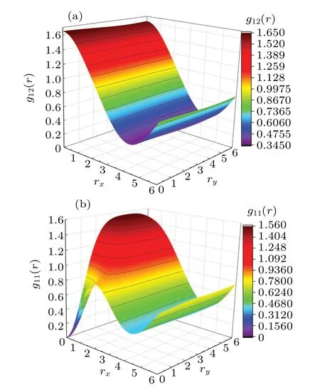
Fig.8.The pair correlation function gσ1,σ2(r) at ground state for Ne =12 in the region d/lB <dc/lB.We observe a stripe ground state.(a)The interlayer correlation function g12(r).(b)The intralayer g11(r)correlation function.
4.Discussion
When we consider a system of Fermi gas,the interactions between fermions could be described via a potentialV(r).Early researches for superconductivity in heavy-fermion systems and superfluidity in liquid3He suggested the importance of an effective attractive potential.[65–67]The strong attractive coupling will drive pairs of fermions to be tightly bound.[67]The two-body tightly bound state can be described by composite bosons(CB).People have realized the pair states in ultracold atomic gases.[68,69]In ultracold atomic gases, the effective interaction potential can be tuned from negative value to positive value with Feshbach resonances related to a magnetic field.[70]In the strong attractive potential,strongly paired bosonic molecules condensation can be predicted.[71,72]The paired fermionic superfluid can be introduced to quantum Hall effect regimes with an effective field theory description.[72,72]In this section we will describe the phase transition based on the developed effective field theory.
The singleν=1/2 two-dimensional electron gases under magnetic field realize a composite Fermion liquid(CFL).Electrons attaching opposite flux quanta can be described as e-CF and h-CF, respectively.In the limit ofd/lB →∞, the electron and hole composite Fermion liquids are realized.People have proposed that eCF–hCF pairs drive bilayer quantum Hall system into a Bose–Einstein condensate phase as the interlayer interactions become strong enough.[28,63]In the limit ofd/lB →0,the attractive interlayer potential leads to bound states.The two limits can be considered as single fermionic atom limit and paired bosonic molecule limit.The composite boson carries two charges and two masses compared to a single fermion.We can have the constraints
whereNeis the total number of electrons.We introduce the fieldas the pair bosonic field.Then we can write the effective lagrangian density as
The fieldψσdescribes the composite Fermion fields of spin-σ,andaσis the corresponding Chern–Simons(CS)gauge field.aσattachesθ/πflux which is related toψσ.We setθ=2πforνσ=1/2.When we consider an opposite magnetic field,we needA↑=-A↓in average and setξ=-1 to indicate the opposite directions for different spins.[73]TheℒBdescribes the pair fields.Here the parameterδis always used in tuning the repulsive and attractive interaction in ultra cold gas.[72]The CF field in each layer is coupled to pair fieldΦvia thegterm inℒ.Generally, people use a mean field treatment ash=g〈Φ(r)〉to estimate the phase diagram.If〈Φ(r)〉/=0,we can claim that there exist the composite bosons.The CB sees no external fieldAand carries double charges.The peaked curves ofg12(r)atr=0 suggest the existence of bound state.The existence of superfluidity is denied by the peaked curves ofg11(r)at smallr.The results in Fig.8 indicate that a stripe state is formed.When〈Φ(r)〉vanishes,we claim that the two CF fields construct CFL respectively with effective opposite charge which attach 2 units of flux.The introduced field consists of CFs asψ↑ψ↓,which drives a first order phase transition from an exciton stripe phase composed of eCF–hCF bound pairs to an eCFL–hCFL phase.
5.Conclusion
By analyzing the energy spectrum,we characterize a critical point atdc/lB=0.68.When separationdincreases acrossdc,a significant collapse of degeneracy,energy levels crossing and discontinuous first-order derivative curves of the groundstate energy could be observed.In the regiond <dc, the states in each level are highly degenerate, and the the degeneracy is a signal of the spontaneous breaking of translational symmetry.[61]In the regiond >dc,the high degeneracy is removed.The system goes through a crossover from thed →dclimit to the largedlimit.
The pair-correlation functiong12(r) shows the evidence of strong bound pair atr=0.Whend/lB <dc/lB,the strong effective attractive potential makes it easier to bind electrons with opposite spins.The ferromagnetic ground state is destroyed.The peak ofg12(r) atr=0 andg11(r) atr~2.5 indicate an exciton stripe state.Asd/lBgrows throughdc/lB,the behavior of pair correlation functions indicates an eCFL–hCFL phase.We follow the effective field theory developed by Yang[72]to understand the phase transition.CF is constructed by electron attaching two fluxes.Opposite flux leads to opposite effective charge.The competition between the interlayer interaction and the intralayer interaction drives the phase transition.Whend/lB <dc/lB, the effective attractive interlayer interaction drives the eCF to bind with hCF.The composite Bosons with effective repulsive potential form the stripe states.When the two layers are decoupled,the bound state is destroyed.CFs form CFL with opposite effective charges in each layer.
Appendix A:The density operator
Here we show the derivation details of the density operator when a flux index is considered.Theρξ,σ(r)is defined as

This relation could similar be got via
Appendix B: Particle–hole transform and opposite fluxes
Interaction potential could be defined asVee(q) =-Veh(q), where ’ee’ is for electron–electron interaction and’eh’is for electron–hole interaction,respectively.
In the main paper,we have discussed the relations of the density operator under the index of flux and under particle–hole transformation.We omit the spin-index and use e for electron, h for hole and±for flux.We define the classical two-body electron–electron interaction Hamitonian asHee=∑qVeeρe+(-q)ρe+(q).For flux flip and particle–hole transform,we easily have
Then we define the electron–hole interaction Hamitonian under uniform fluxHehand the electron–electron interaction Hamitonian under opposite fluxH+-
Acknowledgement
We would like to thank Zhu Zheng for discussions.
杂志排行
Chinese Physics B的其它文章
- Dynamic responses of an energy harvesting system based on piezoelectric and electromagnetic mechanisms under colored noise
- Intervention against information diffusion in static and temporal coupling networks
- Turing pattern selection for a plant–wrack model with cross-diffusion
- Quantum correlation enhanced bound of the information exclusion principle
- Floquet dynamical quantum phase transitions in transverse XY spin chains under periodic kickings
- Generalized uncertainty principle from long-range kernel effects:The case of the Hawking black hole temperature
