基于MBSE的智能汽车信息物理系统建模方法*
2023-10-08徐天啸梁浩赵静高小栋闫涵
徐天啸 梁浩 赵静 高小栋 闫涵
(国汽(北京)智能网联汽车研究院有限公司, 北京 100176)
Abbreviations
CPSCyber-Physical System
ICVIntelligent and Connected Vehicle
IVCPS Intelligent Vehicle Cyber-Physical System
CCSCloud-based Control System
TBSEText-Based Systems Engineering
MBSEModel-Based Systems Engineering
SysML Systems Modeling Language
RFLPRequirement analysis-Functional analysis-Logical analysis-Parametric calibration
CPCCCloud-Based Predictive Cruise Control
0 Introduction
Under the rapid development of information technologies, vehicles are developing in the direction of intelligence and connecting, the application of Cyber-Physical System (CPS) in the Intelligent and Connected Vehicle(ICV)field becomes an important research topic[1-2].Intelligent Vehicle Cyber-Physical System (IVCPS) obtains real-time information of roads, traffic and vehicles from the Cloud-based Control System(CCS),uses the computing ability of the cloud to quickly calculate the driving strategy of the car and transmit it to the ICV.This control mode can significantly improve the safety of vehicle driving and reduce energy consumption,which is of great significance for the development of vehicles in the direction of low carbon and energy saving[3-4].
At present, research on CPS, ICV and CCS focuses on network architecture and control algorithms. Xia et al.[5]designed an intelligent transportation network physical control system based on CCS, the simulation results show that the system improves the dynamic performance of the traffic control system.Based on CPS theory,Li et al.[2]proposed CCS architecture for ICVs, which is committed to connecting the 2 main fields of intelligent transportation system and ICV, aiming to accelerate the development of ICV. For control algorithms, Li et al.[6]solved the optimal speed using accurate vehicle and fuel consumption models on a cloud computing platform and developed field experiments. Li et al.[7]performed predictive cruise control for heavy duty commercial vehicles on the highway by predicting slope information. Gao et al.[8]considered the influence of intersection queuing length and dissipation time on vehicle driving,proposed a queuing dissipation time estimation model, which saves bus energy consumption and reduces waiting time. The above studies have achieved many good results. However, the research on architecture is often only theoretical from the perspective of requirements, it ignores the feasibility of application, the research on models and algorithms often needs to first determine the fixed architecture and specific scenarios, when the elements of the architecture or scene change,the model and algorithm need to be adjusted. Therefore, it is necessary to realize the collaborative design, joint simulation and system integration of IVCPS,so that the requirements, architecture, model, algorithm and application of IVCPS are coordinated,the compatibility and reusability of the architecture are improved. Systems engineering- based methods can solve modeling problems of such multi-domain, multi-disciplinary complex systems.
The traditional system engineering field uses the Text-Based Systems Engineering (TBSE) method[9-10],which realizes the task assignment, information interaction between departments and information exchange among different disciplines through a series of documents, tables, drawings and diagrams, such as operation documents, specifications, interface definition documents and architecture specifications. However, TBSE has the disadvantages of poor requirements traceability, insufficient reuse and scalability. In recent years, MBSE[11-13]is proposed to address these disadvantages and gradually becomes a popular method in the field of systems engineering modeling. MBSE uses the model to express the requirements, design, analysis and verification process of a system in the whole life cycle. MBSE can realize the digital and graphical expression of the system through the model so as to improve the efficiency of system design. Many research institutions have explored the application of MBSE theory in various industries, different modeling languages, tools and processes are proposed,such as Harmony SE method[14], object-oriented systems engineering method[15]as well as Magic-grid method[16],et al. These studies are applied mainly in the fields of aerospace[17], nuclear energy[18]and automated factories[19].There is no public research in fields of ICV and CPS.
To address the engineering modeling issue of complex systems of IVCPS, this paper proposes a modeling method for IVCPS based on MBSE.Firstly,the overall architecture of IVCPS is clarified, the "V" model of the IVCPS architecture is established.Then,a system modeling process based on requirement-function-logic-parameter is proposed,it realizes the forward design and modeling of IVCPS architecture. Finally, the typical application scenario case of IVCPS proved that the proposed MBSE method can realize the transmission of status, data,the layer-by-layer progression and correlation from requirements to solutions, make the high traceability of functions and architectures to requirements. The modeling of multidisciplinary and multi-domain complex systems under a unified architecture is completed,which effectively improves the interactivity, reusability and compatibility of IVCPS system modeling.
The paper is structured as follows. Section 1 introduces the overall architecture of IVCPS. Section 2 proposes the modeling method and process of IVCPS based on MBSE. Section 3 gives the cases of IVCPS modeling based on MBSE.Section 4 concludes the paper.
1 Overall Architecture of IVCPS
IVCPS is a typical complex cyber-physical system that integrates automotive, transportation, information and communication systems. To perform sensing, decision-making,planning and control,this system connects the physical layer and the cyber layer.At the cyber layer,the applications of decision-making and control algorithms for vehicles and traffic lights can comprehensively improve the safety and efficiency of vehicle driving and traffic flow.The overall architecture of IVCPS is shown in the Fig.1.
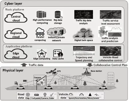
Fig.1 Overall Architecture of IVCPS
The cyber layer, also known as the cloud control platform, consists of 2 parts: the basic platform and the application platform. The basic platform is divided into central cloud and regional cloud according,which can effectively collect and process real-time road traffic data provided by vehicles and roadside sensing infrastructure.Regional clouds provide parallel computing and wide-area communication to run real-time collaborative applications on a regional scale, such as an entire city. The central cloud is capable of high-performance computing and big data storage, mainly running non-real-time applications that serve the entire country. The application platform obtains the dynamic data of vehicles and traffic from the basic platform, deploys applications to improve the transportation system,integrates ICV driving applications, intelligent transportation applications, industry management and service applications based on big data.The physical layer mainly includes ICVs and roadside infrastructure, the cloud control platform collects vehicle dynamic data from ICVs,while other traffic dynamic data is obtained through roadside infrastructures.
2 IVCPS Modeling Theory Based on MBSE
This section introduces the IVCPS modeling theory, tools and process based on MBSE, explains each operation in the modeling method in detail.
2.1 MBSE Modeling Language and Tools
The basis of MBSE is a standardized modeling language.The traditional commonly used language is UML. With the increasing complexity of system modeling, research institutions have extended UML to meet the needs of complex system modeling, and established a new modeling language SysML that is superior to UML. SysML can meet the requirements of system description, design,analysis and verification in multiple fields including hardware, software, information and manufacturing.Therefore,this paper chooses SysML as the modeling language for IVCPS.
Another important element of MBSE modeling is the modeling tool,which needs to ensure the consistency and integrity of the model when the model is changed. Sys-ML-based modeling tools include CATIA Magic,Rhapsody,Enterprise Architect,et al.Among them,CATIA Magic has powerful functions, convenient conditions and moderate implementation costs,its research team is deeply involved in the research and development of SysML standards, which is convenient for further expansion research in the future. Therefore, CATIA Magic is utilized as a modeling tool in this paper.
2.2 IVCPS Modeling Theory
The MBSE-based IVCPS architecture design process is based on the typical development process of MBSE V model, as shown in Fig.2. The V model includes the whole process of requirement development, system architecture design,simulation,verification and validation test.

Fig.2 The V Model of MBSE
The left of the V model is the forward design process, which graphically describes system requirement analysis,functional analysis,architecture design and professional simulation. The right is the verification process from the bottom up, the system model established in the left part is verified by algorithms and software. This paper focuses on the left side of the system architecture design in Fig.2, verification test and other related works will be gradually improved in future works.
The process of MBSE follows the Requirement analysis-Functional analysis-Logical analysis-Parametric calibration(i.e.the RFLP process).Requirement analysis defines the requirements of each level of IVCPS(i.e.,system level, subsystem level, block level and component level) from multiple levels. Functional analysis designs the various functions in the system architecture according to the requirements of each system level and subsystem level. Based on the analysis of requirements and functions, the Logical architecture establishes a architecture that can realize the functions of the system.Parametric calibration provides system solutions and performs multi-dimensional parameter calibration and index issuance to verify and implement the entire system solution.The details of RFLP are shown in Fig.3.
Requirement analysis sorts out the requirements of each element of the system and establishes the traceability relationship between the requirements and the system elements.At the same time,it establishes the traceability relationship between top-level requirements, sub-requirements and sub-requirements aim to ensure the consistency of design. Finally, the requirement traceability matrix and requirement coverage rate are used to determine whether the requirements have been met, so as to establish a complete requirements model.
Functional analysis divides system activities based on different requirements, establishes accurate system use cases to correlate system elements, requirements and functions. Then, the use cases at different levels are decomposed step by step to complete the mutual traceability of system requirements and functions. Finally, the activity diagram is used to describe the implementation process of the system function and indicate the input and output parameters of each activity node in the activity process. The activity diagram can grasp the associated information of system requirements and ensure that when the top-layer requirements change,the relevant requirements can be quickly located and the impact of requirements changes in the system can be analyzed.
Logical analysis establishes an internal block diagram and defines the system logical architecture according to the decomposition results of the system function.Then it defines the subsystems and functional blocks that make up the system, constructs the state diagram and sequence diagram at the same time to clarify the state parameters and information interaction of the subsystems and internal blocks.
Parametric calibration uses parameter diagrams and block definition diagrams to describe the hierarchy of system, subsystem and internal blocks of the system as well as the interaction relationship between system parameters and information. At the system level, according to the system operation plan and strategic requirements, it is necessary to determine the key performance parameters of system, then decompose and distribute the key performance parameters to each subsystem to form an architecture scheme that meets the system requirements.
Furthermore,each system requirement is modeled one by one until all requirements can be met, subsystems at all levels are associated and combined from bottom to system level to form the architecture design scheme of the entire system. The architecture is integrated with other models for simulation purpose,the optimal parameter calibration scheme is selected as the final scheme of the system according to the evaluation results.
3 The Case of IVCPS Modeling Using MBSE
3.1 IVCPS application Scenario Description
IVCPS has different definitions from different positions and perspectives: Vehicle-Road Cloud Integration System (VRCIS), Intelligent and Connected Vehicle System(ICVS) and Cloud-Based Predictive Cruise Control System (CPCC). Most of the current research focuses on ICV under cloud- based condition, this paper studies the CPCC scenarios for the adaptive control strategy of ICV under cloud control system.
The CPCC is shown in Fig.4, including CPCC cloud control platform, intelligent and connected buses,roadside equipment, map platform, other vehicles and operation management departments as other systems that interact with the CPCC system in the operating environment. In this scenario, the intelligent and connected bus sends vehicle operation data to the cloud control platform, generates adaptive cruise speed and feedback command execution data according to the vehicle speed planning sequence and vehicle end point equipment, the cloud control platform updates the bus driving strategy in real time based on the vehicle operation data feedback. As a complex system, the model establishment of CPCC involves the coordination and cooperation of multiple subsystems and multiple elements, its system modeling needs to realize the integration of CPCC top-level architecture framework design, system requirements analysis, function assignment of various subsystems, logical design, system parameters calibration, simulation algorithm development and parameter management.

Fig.4 CPCC System Elements
3.2 Requirement Analysis
According to RFLP modeling process, the first step is requirement analysis. The purpose of requirement analysis is to obtain the requirements of stakeholders in the system, clarify the system definition, design requirements and constraints from users’needs, realize the categorical, hierarchical optimization organization and management of requirements. CPCC involves vehicles, transportation, communications, maps and other fields. In order to ensure cross-field coordination and universality in various fields, this paper refers to some exist architecture framework,such as the US Department of Defense Architecture Framework,the UK Department of Defense Architecture Framework, the Open Organization Architecture Framework, et al., proposes a framework as shown in Fig.5.
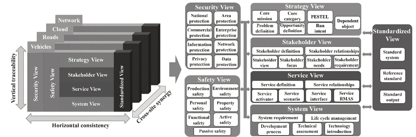
Fig.5 CPCC Architecture Framework
The framework consists of 7 levels: strategy, stakeholders, standardization services, security, protection and system. Horizontally, it aims to ensure the consistency of the requirements of each dimension;Vertically,it aims to ensure top-down granularity of requirements within the 4 views of strategy, stakeholders, service, system and bottom-up traceability of requirements within the 4 views.It is further possible to reach consensus on the positions of different members.
After the requirements are defined, the requirements model is established by using the SysML.The process is shown in Fig.6.Firstly,the ICV system framework is analyzed and sorted out. Moreover, various requirements that need to be met are clarified, the requirements are sorted out according to the process specifications.After the requirements are clarified, modeled, the correlation between the various requirements is then clarified according to the requirements list,such as the stakeholder requirements need to be determined according to the strategic requirements list, then the service requirements and system requirements are guided, a clear traceability relationship is formed between the various requirements to verify whether the requirements are met. In this process, it is necessary to analyze and describe the requirements with the help of requirement lists,requirement diagrams, use case diagrams and activity diagrams to achieve the overall modeling of requirements. According to the above method, the top-level requirements list and requirements diagram of the CPCC are shown in Tab.1 and Fig.7 respectively.

Fig.6 Requirement Analysis Modeling Flowchart

Fig.7 CPCC System Top-level Requirement Diagram
After the top-level requirements are determined,the 7 types of requirements should be decomposed in details, taking the system requirements as an example, the information is mostly based on tables or documents,so in the process of establishing the system requirements model, the documents are organized into an itemized requirements list (Tab.2) and converted into a requirements diagram (Fig.8). The connection with the cross-circle endpoint in Fig.8 represents the composition or decomposition relationship between the requirements, the graphic at the end of the non-cross circular break point is used to describe the requirements in more detail, the system requirements model includes sub-requirements in 6 aspects, such as network communication requirements and security control requirements. Sub-requirements can be further subdivided. For example, network communication requirements can be divided into road cloud communication requirements, cloud communication requirements and vehicle cloud communication requirements (Fig.9).The requirements diagram shown in Fig.8 and Fig.9 not only realizes the graphical modeling of each requirement,but also uses decomposition, traceability and other correlations to manage the requirements, such as strategystakeholder requirements traceability relationship as shown in Fig.10. Through the requirements traceability matrix can intuitively and clearly obtain the logical relationship between requirements. The above is an example of system requirement modeling,the requirements modeling of the remaining 6 levels also follows the same process and methodology, so as to complete the requirements modeling of the entire system.
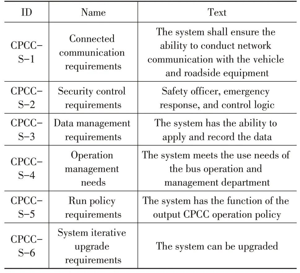
Tab.2 CPCC System Requirements Level List
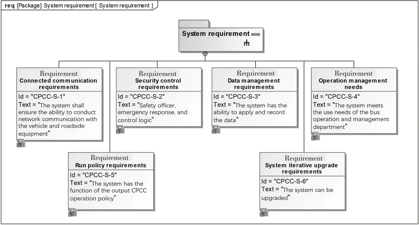
Fig.8 CPCC System Requirement Level Diagram
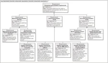
Fig.9 Expand Diagram of CPCC System Network Communication Requirements

Fig.10 Strategy-stakeholder Requirements Traceability Relationship
When there are new tasks or changes in design requirements,the graphical and intuitive CPCC system model built based on SysML can easily and quickly complete the operations by querying,adding,removing and modifying the model.SysML significantly improves the reusability of model and design information,reduces operational redundancy and enhances the efficiency of model.
3.3 Functional Analysis
Based on the system requirements model, a functional model of CPCC system is established. The relationship between participants and use cases in the CPCC system is described by the use case diagram of SysML.More specifically, using activity diagram is helpful to refine the process of describing the relevant functions of the system. While, using the state diagram is helpful to analyze the state of the relevant components of the system in operation. The process of functional analysis modeling is shown in Fig.11. CPCC system includes intelligent and connected bus driving, cloud control platform greenwave traffic strategy planning and green-wave traffic scheduling management, according to the target function and participant relationship design, its use case diagram is shown in Fig.12, each use case corresponds to one target function of the system. The following takes the cloud control platform green- wave traffic strategy planning function as an example.
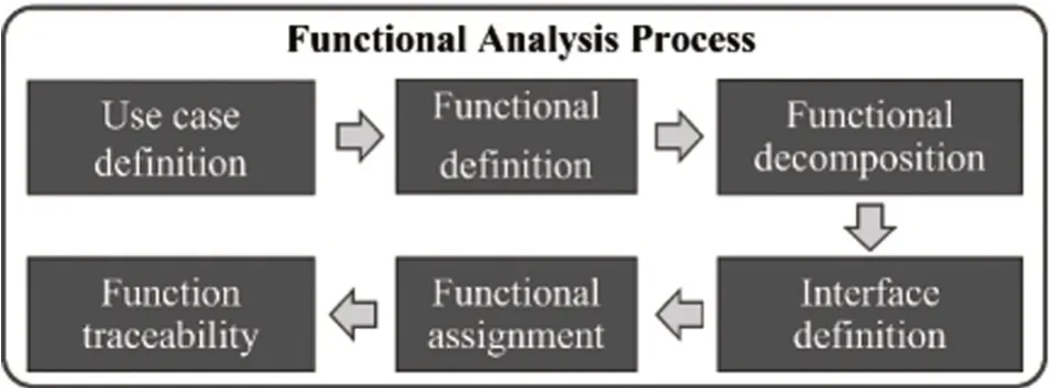
Fig.11 Functional Analysis Flowchart
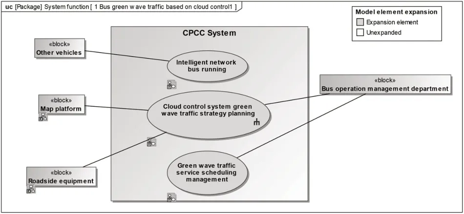
Fig.12 CPCC Use Case Diagram
The green-wave traffic strategy planning function includes 10 sub-functions, such as obtaining bus operation data, obtaining bus operation plan, identifying traffic flow and identifying signal lights. Its use case diagram is shown in Fig.13(a). The relevant parties of CPCC system include intelligent networked buses, bus operation management departments,map platforms and roadside equipment. Then, the use case diagram is expanded and defined separately.Taking the function of obtaining bus operation data in the 10 sub-functions as an example, its function is expanded as shown in Fig.13. Fig.13(b) describes the activity of obtaining bus operation data, the CPCC cloud control platform requests bus operation data,then intelligent and connected bus processes the request and send operation data to the cloud control platform,the cloud control platform receives the driving data and uses the regional cloud for processing. The received driving data is decomposed to obtain specific parameters such as vehicle position,speed and ID,outputted to the next associated function. The above is only the modeling process of one sub-function, the remaining sub-functions follow the same modeling method and process. Finally, the established functional model elements are traced to the requirement model, as shown in Fig.13(c), so that requirements, stakeholders and system functions are related to each other.
The above functional analysis process uses the activity diagram to specifically describe the implementation process of the green-wave traffic strategy planning function of the CPCC system cloud control platform,which indicates the input and output parameters of each activity node of the cloud control platform in the traffic strategy planning process,so that the source and subsequent associated information of each system demand can be mastered.
3.4 Logical Analysis
The functional analysis determines of the CPCC system behaviors.Then the logical analysis will establish the data interaction interface and data flow types for the system behavior based on the results of the requirements analysis and functional analysis. Firstly, the logical analysis defines the logical structure of the system using the block definition diagram,uses the internal block diagram to define the internal structure and attributes of each subsystem.Then it clarifies the connection relationship between the blocks in the system. Finally, it determines the relationship among blocks and external material,data and energy. The process of logical analysis can be divided into 3 steps:
(1) Summarize the decomposed logical components to form a system composition.
(2) Define the logical components interface and its flow attributes according to the matching functional interface and object flow.
(3)Determine the association relationship of the logical components of the system.
The cloud control platform green-wave traffic strategy planning function described in the above section is an example, its function is realized in the CPCC cloud control platform and the definition diagram of the CPCC cloud control platform block is shown in Fig.14, including the cloud control application platform and the cloud control basic platform. Moreover, the cloud control application platform includes intelligent bus management platform, predictive bus green wave traffic application block and other blocks. The predictive bus green wave traffic application block can be decomposed into data processing, decision generation and policy execution monitoring sub-blocks, the decision generation sub-block can be further decomposed.

Fig.14 Cloud Control Platform Block Definition Diagram
After establishing the architecture of CPCC cloud control platform, the interactive interface of each component,substance and information is clearly defined according to the definition diagram. Taking the data processing system, decision generation system, policy implementation monitoring block as examples, their interface definition is shown in Fig.15. The defined interface describes various physical parameters,such as map information,vehicle information, traffic flow, signal light information,roadside information, et al., and indicating the information interaction relationship of 3 sub-blocks of data processing, decision generation and strategy implementation monitoring. The established model relationships can analyze whether all system requirements have been met, as shown in Fig.16. Finally, the association relationship between each component of CPCC cloud control system is determined by the internal block diagram, as shown in Fig.17, the interface definition and interaction relationship of each block inside the CPCC cloud control basic platform and the cloud control application platform are obtained. The explanation of the functions of each stage in Fig.17 is shown in Tab.3.
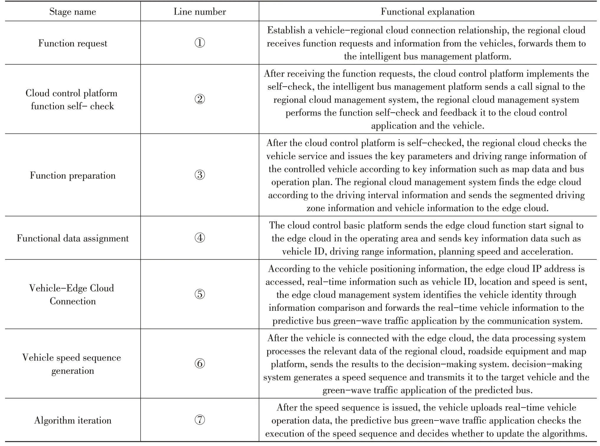
Tab.3 The Explanation of the Connection Relationship Between Cloud Control Platform Modules
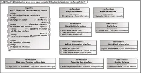
Fig.15 Predictive Public Transport Green Wave Traffic Application Block Definition Diagram

Fig.16 The Relationship Between the Decision Generation Block and the Satisfaction of the System Operation Strategy Requirements

Fig.17 Internal Block Diagram of Cloud Control Platform
3.5 Parametric Calibration
After the logical architecture design and model construction are completed, it is necessary to calibrate the model parameters, generate multiple scenario simulation test schemes and choose the best one to realize the in-the-loop verification for system architecture, so as to realize the application of system functions and logic.
The parameter calibration process of CPCC system is shown in Fig.18.
(1) The first step is to set the parameter limit value range in the architecture model and adjust the system scenario simulation parameter settings.
(2)The second step is to run the scenario simulation model, output the evaluation parameters and process the results.
(3) The third step is to evaluate the system design and allocate indicators.
(4) In the fourth step, the simulation results of the complex large system are sent to the key parameters in the member system to achieve the distribution of system operation indicators.
The system parametric calibration method establishes the simulation verification interface block diagram by SysML.Then,SysML is utilized to realize the unified call and control of the whole process of multiple simulation software. Furthermore, the CPCC system architecture should be optimized from multiple dimensions, it is necessary to realize the scheme trade-off under the specific position dimension of the CPCC system.Finally,the optimal architecture and implementation scheme are selected to meet the operation requirements of complex large systems, the key parameters of member systems such as vehicles,roads,clouds and networks are calibrated.
Repeat the above process for each subsystem and subblock of the CPCC system until every function and every requirement in the system is met,finally a CPCC system architecture model can be formed after verification,confirmation,weighing and evaluation.
4 Conclusions
This paper studies the application of MBSE method to IVCPS modeling and architecture design:
(1) The RFLP modeling process is utilized to realize the MBSE system modeling of IVCPS, including 4 stages of requirement analysis, functional analysis, logical analysis and parametric calibration.The system model is constructed by applying SysML and Catia Magic to realize the visualization and intuitive description,to form an integrated system architecture with requirement-functionlogic-parameter progressing and related layer by layer.
(2)The system requirements of IVCPS are sorted out through requirement analysis and requirement diagram,the traceability matrix is used to establish the requirement traceability relationship between different levels.
(3) Through functional analysis and use case diagram, several functions to meet the requirements of the IVCPS system are determined,the relevant activities carried out by the functions are analyzed by applying the activity diagram, the correlation and traceability relationship of the functions and requirements are established.
(4) Through logical architecture design and sequence diagram, the logical architecture, which meets the system requirements and realizes the system functions,is designed.
(5) Through parametric calibration, block definition diagram, internal block diagram and parameter diagram,the logical architecture is clarified and realized,the traceability matrix of system requirements and parameters is established to ensure the consistency of design information and requirements.
(6) The results show that the MBSE method has guiding significance for solving the modeling problems of IVCPS complex system,which can enhance the traceability of requirement information, ensure the consistency of design information and requirements, improve the reusability of models and the scalability of architecture, improve the efficiency of overall modeling and architecture design as well.
Conflict of Interest Statement
The authors declare that they have no known competing financial interests or personal relationships that could have appeared to influence the work reported in this paper.
【About the authors】
Tian xiao XU is now a System Architecture Senior Engineer of Cyber-Physical Systems Division in China Intelligent and Connected Vehicles (Beijing) Research Institute Co.,Ltd. His research interests include Modelbased Systems Engineering (MBSE), Cyber-Physical Systems and Systems architecture.

Hao Liang is the director of Cyber-Physical Systems Division in China Intelligent and Connected Vehicles (Beijing) Research Institute Co., Ltd. His research interests include Model- based Systems Engineering (MBSE),Cyber- Physical Systems and Digital Twin Technology.

Jing Zhao is currently working at China Intelligent and Connected Vehicles (Beijing)Research Institute Co., Ltd as a System Architecture Engineer. Her main research interests include Model- based Systems Engineering(MBSE) and Cyber-Physical Systems of rail traffic.

Xiao-dong Gao is a System Architecture Engineer of Cyber-Physical Systems Division in China Intelligent and Connected Vehicles(Beijing) Research Institute Co., Ltd. His research interests include Model-based Systems Engineering (MBSE) and Autono-mous Vehicle Control Technology.

Han Yan is currently working at the China Intelligent and Connected Vehicles (Beijing) Research Institute Co., Ltd as a System Architecture Engineer. Her main research interests include Model-based Systems Engineering (MBSE) and Intelligent High-speed Information Physics Architecture.