Comparison of different noble gas injections by massive gas injection on plasma disruption mitigation on Experimental Advanced Superconducting Tokamak
2023-09-05ShengBoZhao赵胜波HuiDongZhuang庄会东JingShengYuan元京升DeHaoZhang张德皓LiLi黎立LongZeng曾龙DaLongChen陈大龙SongTaoMao毛松涛MingHuang黄明GuiZhongZuo左桂忠andJianShengHu胡建生
Sheng-Bo Zhao(赵胜波), Hui-Dong Zhuang(庄会东), Jing-Sheng Yuan(元京升), De-Hao Zhang(张德皓),Li Li(黎立), Long Zeng(曾龙), Da-Long Chen(陈大龙), Song-Tao Mao(毛松涛), Ming Huang(黄明),Gui-Zhong Zuo(左桂忠),‡, and Jian-Sheng Hu(胡建生)
1Institute of Plasma Physics,Hefei Institutes of Physical Science,Chinese Academy of Sciences,Hefei 230031,China
2University of Science and Technology of China,Hefei 230026,China
3Department of Engineering Physics,Tsinghua University,Beijing 100084,China
Keywords: disruption mitigation, massive gas injection (MGI), Experimental Advanced Superconducting Tokamak(EAST)
1.Introduction
Plasma disruption is a substantial threat to future fusion devices.It rapidly terminates plasma discharge, releasing a vast amount of stored thermal and magnetic energy to damage fusion devices.[1]During plasma disruption,massive heat loads on plasma-facing components(PFCs)occur while thermal quench (TQ), the strong electromagnetic forces and currents are induced in the inner structures of fusion machines,and multi-MeV runaway electrons (REs) are generated during current quench (CQ).[2]Future ITER devices must mitigate plasma disruption to reduce the electromagnetic forces and thermal loads on the inner components to ensure machine safety.[3]Massive gas injection (MGI) has been developed to inject a large amount of noble gas into the plasma before plasma disruption.MGI uniformly radiates thermal energy through the ionization of particles.Further,the high particle density leads to collision frequency high enough to hinder runaway; subsequently, the high plasma resistivity causes the current to decay faster.[4]
MGI system is an advanced method for disruption mitigation.Some associated experiments were carried out on JET,[5]DIII-D,[6]ASDEX Upgrade,[7]EAST,[8]MAST,[9]Tore Supra[10]and Alcator C-Mod.[11]Holmannet al.performed the impurity assimilation measurements for MGI experiments in DIII-D.[12]On the ASDEX Upgrade,MGI of Ne revealed that the electron density reached 24% of RE collisional suppression needed(the so-called critical electron density,nc)[7]for the disruption.[13]Uron Krueziet al.had investigated the impact of MGI on wall conditions and verified the influence of injecting impurities on the machine condition for the plasma pulses after the MGI.[14]MGI shutdown timescales, including cold front, TQ, and CQ durations had rough increasing trends with device size, clearly observed on the Alcator C-MOD, DIII-D, and MAST.[15]However, the same trend was not followed well on JET device.On JET,various pure noble gases and mixed gases were injected into plasma,and timescales,including cooling time,CQ,and mitigation efficiency were investigated.Neon,argon,and the mixtures with deuterium showed much shorter cooling duration compared with pure deuterium and helium.[16]On Tore Supra,comparing all gases(He,Ne,Ar,and He/Ar mixture)revealed that helium produced the longest coolings although the cooling time weakly depends on the gasZ-number.[10]Therefore,this study compared different noble gas injections by MGI on plasma disruption mitigation on EAST to study the plasma shutdown timescales on large scale superconductive tokamak and provide some key data reference for ITER device.
This study systematically compared the effects of different gas injections on plasma disruption mitigation.It mainly includes the analysis of the critical duration of pre-TQ, TQ,CQ, and radiation distribution with different gas injections during the plasma shutdown process.Section 2 describes the MGI development on EAST.Section 3 compares the shutdown timescales and radiation distribution by various gas injections.Finally,Section 4 presents the summary of this study.
2.Development of MGI on EAST
Figure 1 shows the structure and operating principle of the MGI fast valve.The fast valve is closed under the spring preload during the non-working mode.With the trigger signal generated,the power supply system gives a strong pulsating current to the coil.The spool induces strong eddy currents through electromagnetic induction.According to the Lenz’s law, a large change in a short time in the magnetic flux produces a massive electromagnetic repulsion force.The valve port opens when the repulsion force exceeds the spring preload.The power supply system’s output voltage can adjust and control the electromagnetic repulsion force.Additionally,the valve port’s opening degree and opening time can be controlled to adjust the amount of gas injected.
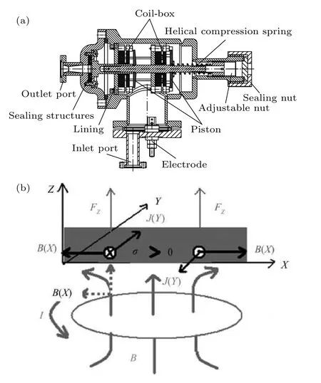
Fig.1.(a)Cross-sectional view of fast valve.(b)Eddy-current repulsion in the fast valve.
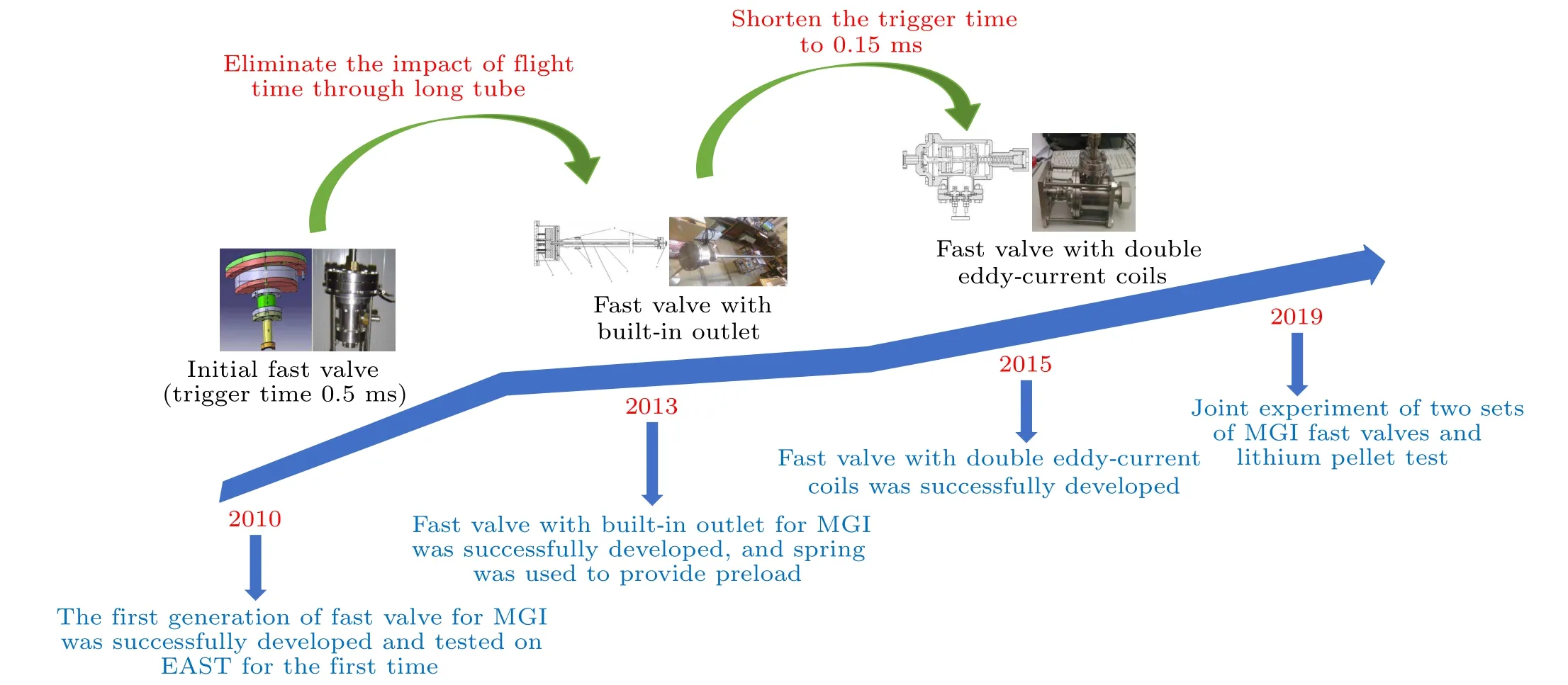
Fig.2.The development of MGI devices on EAST.
The EAST had developed the MGI system since 2010.In 2010, the trigger time could be controlled at 0.5 ms, and the amount of injected gas could be adjusted between 0 Pa·L to 7×10⁴Pa·L.Such parameters were comparable at the advanced level globally.However,the time of plasma disruption,a basic requirement for disruption mitigation,was very short.The MGI disruption mitigation device with a shorter response time could have much time left for rupture prediction to meet future fusion reactor requirements.Therefore, in 2013, the EAST team developed the second generation of MGI with a built-in fast valve.The main feature of this device is that the gas is already in the tube before the MGI is triggered.The gas can quickly enter the plasma after a 0.5 ms trigger time.Compared with the previous generation device, the mitigation device can respond to the trigger signal faster by eliminating the gas transit time in the pipeline.In 2015,the EAST team successfully developed the fast valve for MGI with double eddycurrent coils, with a shortened trigger time of 0.15 ms.The MGI device uses a new sealing system to attain a maximum working pressure of 5 MPa and a maximum working voltage of 3 kV.At the same time, it reduces the volume of the MGI device to only about 4 dm3(250 mm×150 mm×100 mm).High pressure, atmospheric volume, fast response, and small size are the main advantages of the MGI fast valve on EAST.
MGI fast valves on EAST conducted a large number of experiments using He/Ne/Ar gas.Further, a series of investigations around disruption prediction, disruption mitigation,lithium pellet injection, and radiation asymmetry resulted in many achievements.It accumulated much experimental data for future fusion reactor design.Figure 2 shows the development history of MGI devices on EAST.
Figure 3(a) demonstrates installation and relevant diagnosis positions.MGI fast valve was installed at the O port horizontal lower position.This study used critical diagnostics,including an absolute extreme ultraviolet (AXUV) photodiode array and a multichannel middle-plane electron cyclotron emission(ECE).These were installed at the P port,as shown in the top view in Fig.3(b).
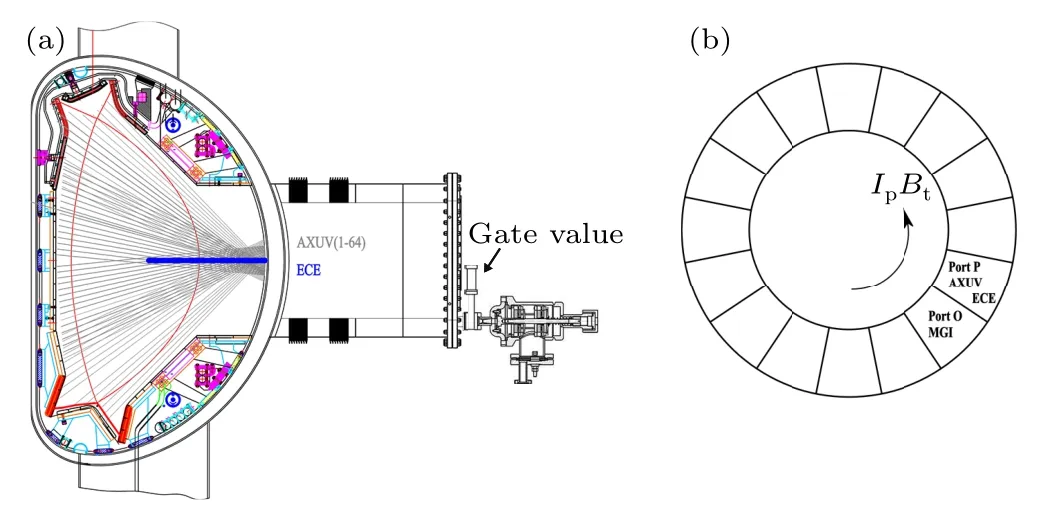
Fig.3.(a) The installation position of MGI.(b) Top view of relevant diagnostics.
3.Experimental results
During plasma shutdown experiments, massive gas was injected into the plasma vessel by MGI.Some key phases,including gas flight from the valve to the plasma edge,gas permeation from the plasma edge to the core, and the thermal and current quench,successively occurred and were observed.The reference of a critical time in the disruption process was established in shot 75647 to analyze and understand each fundamental timescale in the plasma disruption process.Figure 4 shows a typical plasma disruption process triggered by Ar-MGI.The main plasma parameters wereIp= 0.4 MA, andne=2.1×10¹⁹m−3in the upper single null(USN)configuration.
MGI fast valve receives trigger signal at 4 s.It takes about 4 ms flight time to reach the plasma edge,which can be indicated by the edge radiation rise,as shown in Fig.4(c).Meanwhile, it enters the pre-TQ duration, also called the cooling time.[17]Additionally, the pre-TQ duration is defined as the time of flight (TOF) of the gas from the valve to the plasma edge and the duration of the edge cooling process before initiating the TQ.[18]However, this study defines pre-TQ as the time from the arrival of impurities at the plasma edge to the temperature drop of the plasma core.During this phase, the Ar atoms are thoroughly mixed with the plasma and moved closer to the plasma core through the plasma transport process.Throughout the process, the plasma cools with the constant ionization of Ar atoms and the dissipation of plasma energy.Finally,the electron temperature in the plasma core drops suddenly at about 4.01 s.The time span of this process is very short,less than 1 ms,and is called the TQ phase,as shown in Fig.4(d).
After the TQ phase, the current of plasma drops rapidly,and this phase is called the CQ phase.For the EAST device,an 80%–30%interval of the maximum plasma current is found to be a better fit for the CQ phase.[19]In this paper,we continue to use this definition.Figure 4(a)shows that in the discharge experiment,the CQ duration lasts about 5 ms.

Fig.4.A typical process of plasma disruption triggered by MGI.(a)Plasma current,(b)vertical centroid of plasma current,(c)edge radiation measured by AXUV,(d)core electron cyclotron emission(ECE)signal.
3.1.Flight time and a general comparison of different gas injections
First, the flight time of the noble gas is analyzed.Figure 5 shows the relationship between the amount of gas injected and flight time.The flight time decreases slightly with the increase in gas injection amount.However, this trend is not apparent, which suggests that the amount of gas injected is not the decisive factor in determining flight time.The flight time decreases with the decrease in the relative atomic mass of the injected impurity.It is also consistent with the theoretical formula, whereKis the Boltzmann constant,Tis the gas temperature,andmis the atomic mass.
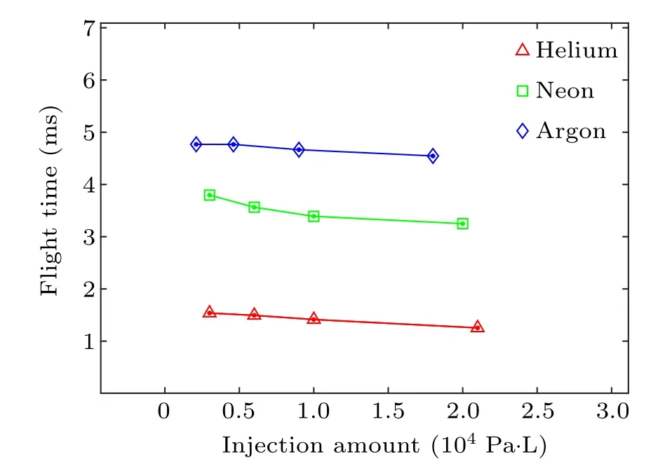
Fig.5.Gas flight time as a function of the injected gas species and quantity.

Fig.6.General comparison of the disruption mitigation effects with different kinds of impurities injection.(a)Plasma current,(b)loop voltage,(c)edge radiation measured by AXUV,(d)stored energy.
Figure 6 depicts the general comparison of the disruption mitigation effects with different impurities injections.Previously we analyzed the influence of flight time.Thus, we aligned the time of impurities reaching the plasma on the time axis, evident by the rising edge radiation signal, shown by the pink dashed line in Fig.6(c).Figure 6(a) shows that the plasma current decay delays with the increasing atomic weight of the injected impurity.Also,Fig.6(c)shows that the radiation intensity caused by highZimpurities at the plasma edge is stronger.The rate of change of the plasma stored energy suggests that the highZimpurities can induce plasma stored energy to drop quickly.The small dash lines show this decreased stored energy rate in Fig.6(d).
3.2.Pre-TQ,TQ,and CQ phases with different gas injections
The pre-TQ phase is one of the most critical phases in the disruption mitigation process.It represents the penetration and ionization of impurity particles in plasma.The MHD unstable modes, which eventually transport the impurities to the plasma core, are also the focus of disruption mitigation research.Figure 7 shows that small atomic mass impurities penetrate the plasma faster.Comparing the pre-TQ duration(0.9 ms–1.1 ms for He,1.1 ms–1.5 ms for Ne,1.4 ms–1.9 ms for Ar) with different gas injection quantities reveals a clear linear relationship between the decrease in pre-TQ duration and the increasing amount of gas injected.The decline rate of this linear relationship also decreases with the reduction in impurity atomic mass.However, this conclusion needs to be further verified by subsequent experiments.This study mentions the injection amount as the normalized relative injection amount,which is the ratio of the number of particles injected to the number of particles contained in the plasma.
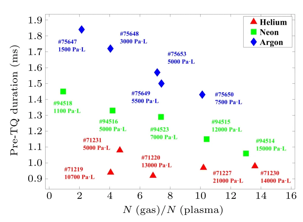
Fig.7.The pre-TQ duration as a function of the relative injection amount(N(gas)/N(plasma)).
After the pre-TQ phase, plasma entered the TQ phase,where the stored energy in the plasma is lost.[20]A large portion of stored energy is removed from the plasma core zone through the scrape-off layer(SOL)and deposits onto the first wall and the divertor plate zones.[21]Figure 8 shows the evolution of plasma core electron temperature (measured by ECE)with time under the different noble gas injection conditions.The plasma discharges exhibit similar plasma parameters, such asIp=0.35 MA–0.4 MA,ne=2.5×10¹⁹m−3–3.0×10¹⁹m−3, USN configuration, and the gas injection amount is similar,∼2×10⁴Pa·L.The shaded area is socalled thermal quench phase (TQ).The highZimpurities injections would make the plasma core electron temperature collapse faster.The subsequent small rise in electron temperature in the plasma core is due to the reheating of the external system.Compared with highZimpurity gas, the lowZimpurity gas has weak radiation rate coefficients.Further, it cannot efficiently mitigate heat load, leading to a long TQ duration.However,slight impurity gas moves more quickly to the plasma,which results in a short pre-TQ duration and requires less time to accumulate impurities before TQ.[22]
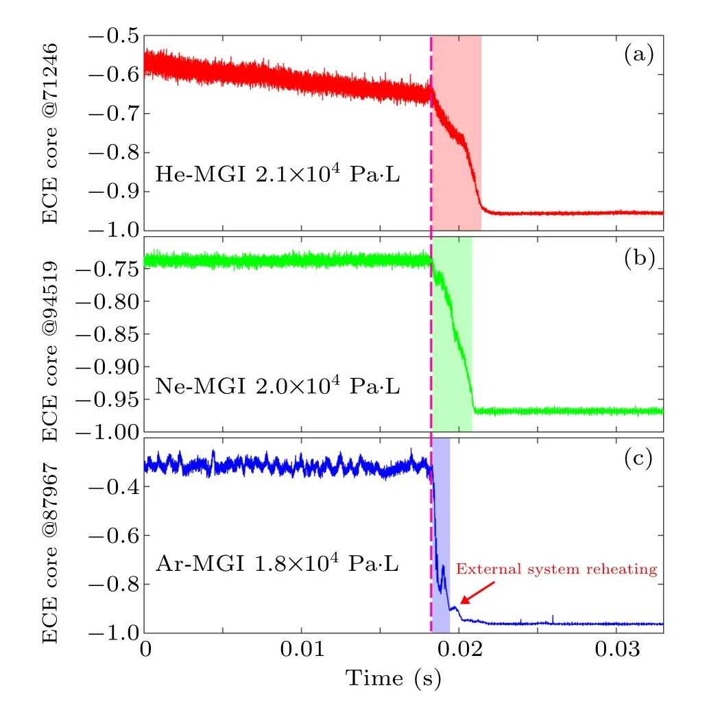
Fig.8.Evolution of TQ with time indicated by ECE core of(a)shot#71246,(b)shot#94519,and(c)shot#87967.The shaded area stands for the thermal quench phase.
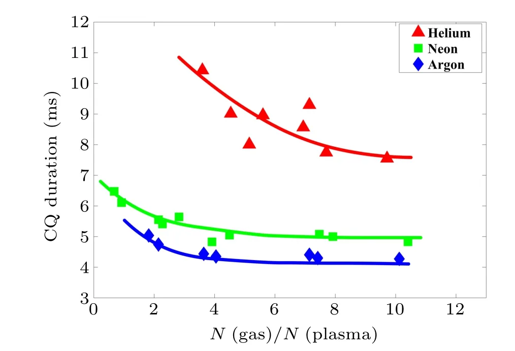
Fig.9.CQ duration with varying relative injection amount.
The effect of different impurity gas species,including Ar,Ne, and He, on the CQ, can be estimated by the plasma current decay time analysis.The CQ phase is closely related to the generation of runaway electrons.Long CQ duration could cause part of the current to hit the first wall before it is relieved,causing ablation damage to the first wall.However,for a very short CQ duration,huge electromagnetic stress induces on the metal components of the device,resulting in mechanical damage.Therefore,controlling CQ duration in an acceptable range by adjusting injection parameters is the key point of current research.Figure 9 demonstrates the relationship between the CQ time and injection amount.The CQ duration is 4 ms–11 ms.More specifically, CQ duration is 7 ms–11 ms for He, 5 ms–7 ms for Ne, and 4 ms–6 ms for Ar injections,indicating CQ reduces with increased atomic mass gas.Meanwhile, the CQ duration decreases rapidly with the increase in injection amount for small injection amounts.When the injection quantity increased to a certain threshold, there is no obvious change in CQ duration.Therefore,it indicates that increasing the amounts of impurities promotes the reduction of CQ duration.The injection amount mentioned here is still the normalized relative injection amount.
3.3.Radiation distribution and poloidal asymmetry
Recently, radiation asymmetry has attracted more and more attention.A few examples are the multifaceted asymmetric radiation from the edge (MARFE) phenomenon caused by high-density experiments in H-mode, radiation asymmetries,[23]poloidal asymmetries during disruption mitigation by MGI on DIII-D,[21]and radiation asymmetries during TQ phase in JET.[24]In this MGI disruption mitigation experiment,strong radiation asymmetry is also observed.Figure 10 suggests the contour map of radiative brightness for different impurities injections by MGI.Figure 10(a) shows that the ionizing radiation distribution of helium is very dispersive.It could be because helium’s very high ionization energy allows more time to disperse in space before being ionized.Subsequently, due to the fastest thermal movement of helium, it can fill the whole space in a very short time.The poloidal radiation distribution is uniform,as shown in area A(Z=0.2 m to 0.5 m and−0.3 m to−0.5 m).Compared with the radiation distribution of Ne and Ar, the radiation occurrence time in the upper and lower regions of helium is very similar.This might be because the helium diffuses before contacting the high-temperature areas that can ionize it, and helium surrounds the plasma from all directions.This also explains the low poloidal radiation asymmetry caused by helium injection.Compared with helium’s radiation distribution,neon’s ionization radiation is mainly concentrated at the upper position(Z=0.1 m to 0.5 m).Figure 10(b)shows such a comparison between areas B and C.Figure 10(c)indicates that compared with Ne and He, the radiation asymmetry of Ar is stronger and more concentrates in the upper region(Z=0.5 m to−0.3 m).It concludes that the lowZimpurities injections can reduce the poloidal radiation asymmetry compared with the highZimpurities injections.Furthermore,it is found that the primary radiation zones of He and Ne are atZ ∼0.2 m–0.4 m andZ ∼0.15 m–0.4 m, respectively.Even though the radiation is uniform for the Ar injection,the primary radiation zone is atZ ∼0 m–0.4 m.These results suggest that the Ar can be accumulated and radiated at the plasma core zone.
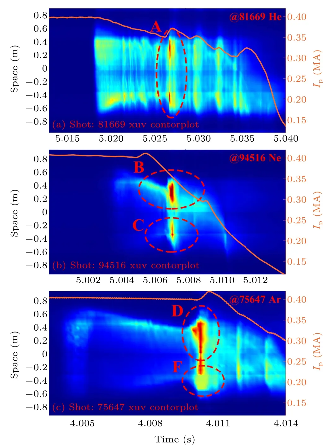
Fig.10.The contour map of radiative brightness for shots #81669,#94516,and#75647.
Besides, it is worth noting that the bursting time of radiation was different when He, Ne, and Ar were injected.When helium was injected, the radiation bursts in the oscillating phase of the plasma current.But, when neon gas was injected,the radiation concentrates on the falling phase of the ionizer current.Furthermore,when argon was injected,the radiation erupts before the plasma current has dropped.The reasons for these phenomena still need to be further researched.
4.Discussion and summary
This study performed different noble gas injection experiments,including He,Ne,and Ar,to compare the mitigation effect of plasma disruption.The study evaluated key parameters such as TOF,pre-TQ,and CQ.The observed durations of pre-TQ,TQ,and CQ in MGI plasma shutdown experiments measured on the EAST device were longer than that measured on the J-TEXT device.[22]However, they showed similar trends.The difference in timescales was possible mainly because of the EAST device’s larger vessel structure size and some larger basic discharge parameters,including plasma current and heating powder.Studies[15]showed that cooling time and TQ duration increases linearly with the increase in minor radius,and CQ duration increases as minor radius squared.This was observed by analyzing the plasma shutdown data with noble gas injection by MGI from Alcator C-MOD,DIII-D,and MAST.The experimental data on the EAST device conformed to these relationships well,providing basic data support for plasma disruption mitigation systems on ITER and future fusion reactors.
This paper compared disruption mitigation experimental results with different noble gas injections by MGI.First, it provided a brief introduction to the development of MGI on EAST devices.Then analyzed the advantages and disadvantages of the previous MGI fast valves.Moreover, comparing the TOF with different noble gas injections revealed that the TOF is mainly related to the gas species and cannot be reduced significantly by increasing the injection amount.The pre-TQ duration decreased significantly with the increased injected gas quantity, indicating a clear linear relationship between them.The TQ phase in the typical disruption process was also analyzed.Notably, the highZimpurities injection caused the plasma core electron temperature to collapse faster.The CQ duration decreased rapidly with increased gas injection amount, followed by saturation.In addition, comparing the radiation distributions revealed that the lowZimpurity injection can improve radiation uniformity.As a next step, we would upgrade the MGI system further and research the effect of mixed gas on plasma disruption mitigation by injecting several ratios of highZand lowZgases by MGI.Meanwhile,we would compare the plasma shutdown by MGI and shattered pellet injection(SPI)on EAST.
Acknowledgments
Project supported by the National Key Research and Development Program of China (Grant Nos.2017YFE0301100 and 2022YFE03130000),the National Natural Science Foundation of China(Grant Nos.12105322,11905138,11905148,and 11905254), the Natural Science Foundation of Anhui Province of China (Grant No.2108085QA38), the Chinese Postdoctoral Science Found (Grant No.2021000278), the Presidential Foundation of Hefei Institutes of Physical Science(Grant No.YZJJ2021QN12), the U.S.Department of Energy contract DE-AC02–09CH11466(Grant No.DE-SC0016553),the Users with Excellence Program of Hefei Science Center CAS (Grant Nos.2020HSC-UE010 and 2021HSC-UE013),and Interdisciplinary and Collaborative Teams of CAS.
猜你喜欢
杂志排行

Chinese Physics B的其它文章
- Interaction solutions and localized waves to the(2+1)-dimensional Hirota–Satsuma–Ito equation with variable coefficient
- Soliton propagation for a coupled Schr¨odinger equation describing Rossby waves
- Angle robust transmitted plasmonic colors with different surroundings utilizing localized surface plasmon resonance
- Rapid stabilization of stochastic quantum systems in a unified framework
- An improved ISR-WV rumor propagation model based on multichannels with time delay and pulse vaccination
- Quantum homomorphic broadcast multi-signature based on homomorphic aggregation