Current sensor based on diamond nitrogen-vacancy color center
2023-09-05ZiYangShi史子阳WeiGao高伟QiWang王启HaoGuo郭浩JunTang唐军ZhongHaoLi李中豪HuanFeiWen温焕飞ZongMinMa马宗敏andJunLiu刘俊
Zi-Yang Shi(史子阳), Wei Gao(高伟), Qi Wang(王启), Hao Guo(郭浩), Jun Tang(唐军),Zhong-Hao Li(李中豪), Huan-Fei Wen(温焕飞), Zong-Min Ma(马宗敏), and Jun Liu(刘俊)
Shanxi Province Key Laboratory of Quantum Sensing and Precision Measurement,School of Instrument and Electronics,North University of China,Taiyuan 030051,China
Keywords: current sensor,diamond,high precision,nitrogen-vacancy(NV)color center
1.Introduction
As a basic physical quantity, it is extremely significant to accurately measure the current.Physicists and engineers have been exploring various methods to measure current.Precise DC current sensing technology is also the need of many scientific research and industrial applications.[1]For example,current source usually realizes high-precision current control through feedback, so high-precision current measurement is very important for accurate current control.The nuclear magnetic resonance gyroscope realizes the precise measurement of angular velocity through the precise measurement of nuclear spin precession frequency in the magnetic field, which requires a high-precision and stable magnetic field.The highprecision current measurement is of great significance to generate the stable magnetic field in the nuclear magnetic resonance gyroscope; Accurate DC current measurement can be used for the evaluation of pA level current generators to calibrate other instruments.[2]In addition, current sensors also have important applications in other industries, such as automotive power management, solar cell system, smart grid and other application industries that need non-contact accurate current measurement.[3]
Current sensors have developed to different degrees at home and abroad, which can be roughly divided into direct measurement and indirect measurement, and there are many kinds of non-contact current sensors.Current sensors commonly used in the industrial field based on Ampere loop law include Rogowski coil current sensor, Hall effect current sensor,[4,5]fluxgate current sensor,[6,7]magnetoresistance(AMR, GMR, TMR, CMR, etc) and current transformer,[8]which have their own advantages and disadvantages in all aspects.In other fields,there are current sensors based on NMR,quantum Hall effect, superconducting quantum interference squid and other principles.They have high requirements for the application environment and are expensive.So far, some technologies are not mature and are in the development or improvement stage.A small amount of them are used in laboratory instruments and equipment.In addition, the optical fiber current sensor based on Faraday magneto-optical effect has good performance for measuring AC large current (such as 100 kA),but its performance problem for DC measurement needs to be solved urgently.
Rogowski coil current sensor and Hall current sensor are relatively traditional current sensors.Their sensitivity is generally low, and their linearity is between 0.05%and 1%.[9,10]New current sensors include optical fiber current sensor based on Faraday magneto-optical effect and GMR current sensor based on giant magnetoresistance effect.They have very high sensitivity, and the linearity of optical fiber type is 0.2%,The linearity of GMR current sensor is between 0.001% and 0.05%.[11–13]It can be seen from the above that for the field of precision detection, the existing current sensors have a common disadvantage that the linearity is not high enough.In addition, optical fiber current sensors are prone to aging.Therefore, a new current sensing method based on diamond nitrogen-vacancy(NV)color center is proposed to solve these problems.It not only has very high linearity and sensitivity, but also has the advantages of low energy consumption and good time stability.At present, there is a large development space for current sensors based on diamond at home and abroad.[14–17]In the field of precision measurement, it has a very broad application prospect.[18,19]
In this paper,a high-precision DC current sensor based on diamond NV color center is proposed.By using a ring-shaped magnetic concentrating structure with open air gap, the magnetic field generated by the current in the conductor is concentrated to generate a magnetic field that has a stable relationship with the current to be measured.In order to achieve high precision,the diamond NV color center is used to accurately measure the air gap magnetic field,and the corresponding accurate current value is obtained by solving the relevant formula.Finally, we experimentally demonstrate the high accuracy and linearity of the DC current sensor.
2.Methods and experiment
Diamond has a strict face centered cubic latticestructure,and there is a carbon atom at any lattice point on the diamond cell.[20,21]NV color center is a stable defect structure, calledC3Vsymmetric structure, formed by capturing a hole nearby after a carbon atom in diamond crystal is replaced by a nitrogen atom.[22]Therefore, there are four possible orientations of NV color centers in diamond.NV color centers in these four directions have equal probability distribution,and the included angle of each NV axis is 109.47◦,as shown in Fig.1(a).Its ground state is triplet state (3A2), which isms=0 state,ms=+1 state andms=−1 state respectively.When the external magnetic field is 0,ms=+1 state andms=−1 state are degenerate double states(ms=±1),and there is a natural zero field splitting with a value of 2.87 GHz betweenms=±1 andms=0 state.[23]The zero-field splitting constant is denoted byD.When the applied external magnetic field is not zero,thems=±1 state is separated from each other by energy level splitting.Among them,two metastable singlets1A1and1E exist between the ground state and excited state of diamond NV color center,and their existence greatly affects the fluorescence signal of NV color center.The transition mechanism of NV color center is shown in Fig.1(b).When a 532 nm green laser is used to irradiate the NV color center, the electrons in the ground state of the NV color center will absorb energy and transition to the excited state3E.The NV color center in the excited state3E has two paths back to the ground state.One path is that the electrons in the excited statems=0 will radiate and transition to the ground statems=0 due to instability, releasing red fluorescence signal.The other path does not release fluorescent, as described below.The electrons in the partially excited statems=+1 have a radiative transition back to the ground statems=+1, some have a non radiative transition,decay to the metastable state1A1and1E,and then have a non radiative transition to the ground statems=0.It can be seen that using 532 nm wavelength laser to excite the NV color center can make the NV color center spin polarized to the ground statems=0.[24]The electron spin state of NV color center can be determined by the collected fluorescence signal.

Fig.1.Schematic diagram of diamond NV color center and energy level structure.(a)The schematics show four possible axes of the NV center in a diamond crystal.(b)The NV center is excited by 532 nm laser and emits photons with a broad spectrum of 637–800 nm.
By irradiating 532 nm laser and scanning the fluorescence signal of NV color center at a certain frequency, the optical detection magnetic resonance (ODMR) spectrum can be obtained.Under the condition of no magnetic field, only 2.87 GHz formant exists.When an external magnetic field is applied, the degenerate statems=±1 occurs Zeeman splitting,forming two frequency formants.And the magnitude of the external magnetic field projected onto the NV axis can be calculated by the formant frequency of the ODMR spectrum.The ground state Hamiltonian(H)of NV color center is[25]
whereDis the zero-field splitting constant of NV color center due to electron spin–spin interaction, and its value is 2.87 GHz;Bis the external magnetic induction intensity;Sis the electron spin state of NV color center, and the value is 1;sx,sy, andszare the components of spin angular momentum in Cartesian coordinates;gis the RAND factor;Eis electric field stress;µBis Bohr magneton.The relation between Zeeman splitting degree(or frequency shift)and external magnetic induction intensity is
Through simplification,we can get
where ∆fis frequency shift;γis the gyromagnetic ratio;his Planck constant;θis the angle between the projection of the NV axis in the magnetic field direction and the NV axis.In this experiment, one of the NV axes of the diamond was adjusted to be consistent with the direction of the magnetic field to be measured,that is,the direction of the NV axis was parallel to the direction of the magnetic field,as shown in Fig.1(a).As a result, the angle between the NV axis and the magnetic field direction is 0 and cosθ=1.
The magnetic field around the energized wire is not a uniform magnetic field, so it is not suitable for direct measurement.In this paper, a ring-shaped magnetic gathering structure with open air gap(hereinafter referred to as the magnetic gathering ring) is used to gather the magnetic field generated by the current in the wire,[26,27]so that a uniform and parallel magnetic field is formed in the center of the air gap of the magnetic gathering ring.And the magnetic field generated by the electrified wire is in direct proportion to the current flowing.From the accurate measured value of the magnetic field, the corresponding accurate value of the current can be obtained.Therefore, combined with the relationship between the magnetic field calculated by ODMR formant frequency shift and the magnetic field and current in the air gap of the magnetic concentrating ring, the current passing through the conductor can be obtained.
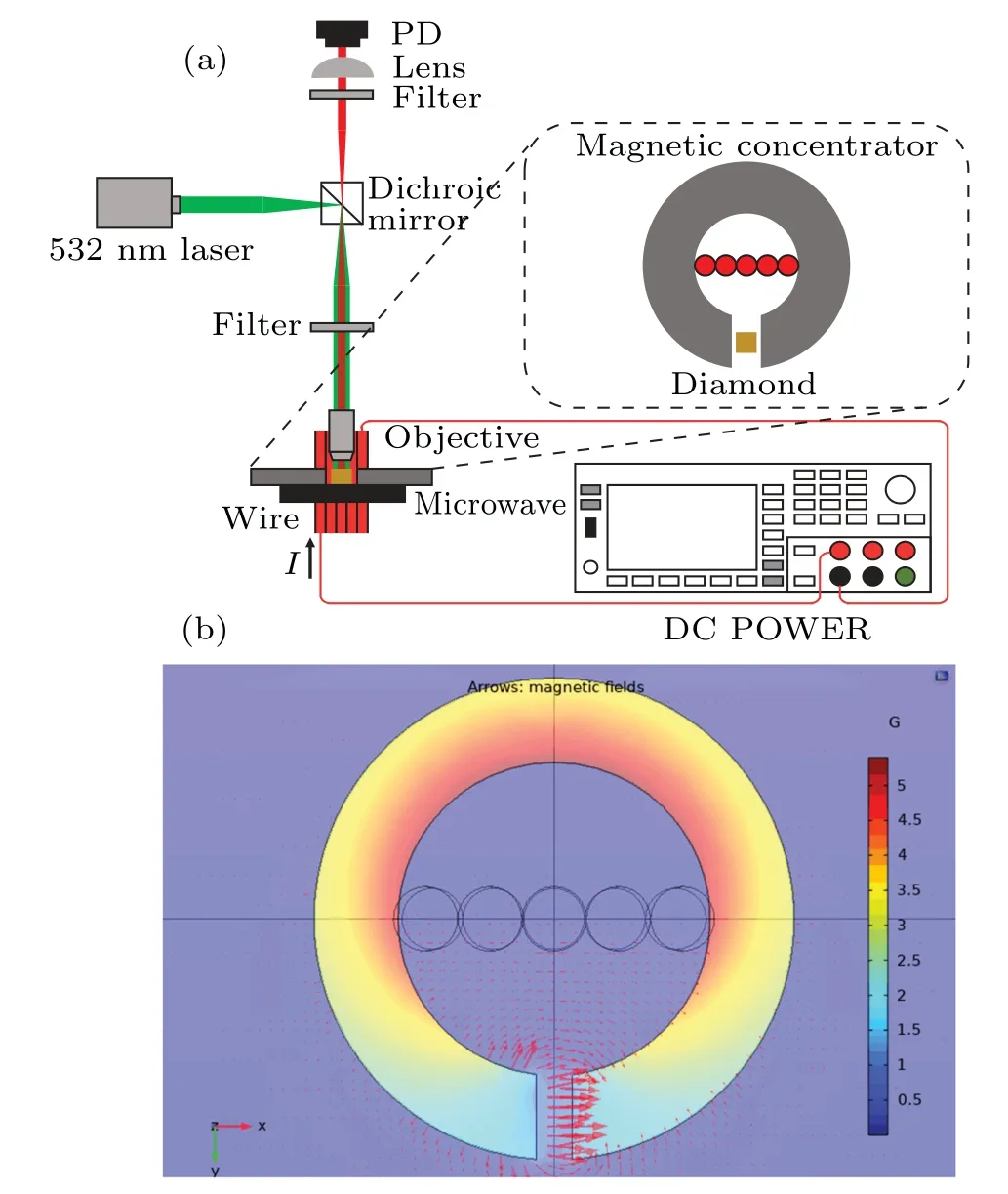
Fig.2.(a) Structure diagram of current sensor.The dotted box shows the partial top view of the magnetic gathering ring and diamond.(b)Simulation diagram of air gap magnetic field of magnetic gathering ring.The results show that a uniform magnetic field can be formed in the center of the air gap.
The sensing system for diamond current measurement is shown in Fig.2(a).The corresponding physical image is shown in Fig.S1 in the supplementary materials.In the experiment, first, the green laser is emitted through the MGL-III-532-100 mW laser, then all the green light is reflected through the long wave pass dichroic mirror (Thorlabs DMLP605R),and through the objective lens(OLYMPUS PLN 10×NA=0.25)focus on the diamond,and the NV color center of the diamond will excite a red fluorescent signal after laser irradiation.The fluorescent signal is filtered by the long wave pass filter(Thorlabs FELH0600)and the long wave pass dichroic mirror,and then focused by the short wave pass filter(Thorlabs FESH0800)and the condensing lens(ACL25416UB NA=0.79),and finally collected by the photodetector(Thorlabs PDA100A2).In addition, current source (KEYSIGHT B2962A) is used to provide stable high-precision DC current of different sizes.The swept microwave is transmitted to the diamond by the microwave source (KEYSIGHT N5183B MXG)connected to the microstrip antenna.The output power is−8 dBm and the frequency range is 2.51–3.24 GHz.In this way, by changing the input current through the current source,the change of the magnetic field in the center of the air gap of the magnetic concentrating ring under different current conditions can be measured,which changes the resonance frequency of the ODMR signal, so as to realize the detection of the current by the diamond NV color center.
The diamond used in the experiment was purchased from ElementSix with a size of 1.5 mm×1.5 mm×1 mm, nitrogen content is about 10−4.Polished surface of diamond(1.5 mm×1.5 mm) is the (100) surface, which is irradiated for 3 h under 10 MeV electron irradiation and then annealed for 2 h under 850◦C.[28–33]The NV color center concentration formed is about 10−6.The functions of magnetic gathering ring mainly include magnetic gathering and antiinterference, so it is appropriate to use soft magnetic material and it is required to have high permeability, low coercivity low loss, high resistivity and high saturation magnetic induction.The material properties of permalloy fully meet the above requirements, and permalloy products have been standardized, low material cost.Therefore, after comprehensive consideration,1J85 permalloy is used in this experiment,which has a high magnetic permeability (initial permeability of 30000 mH/m, maximum permeability of 150000 mH/m),lower than 1.6 Hc/A·m−1coercivity.And 0.8 T saturation magnetic induction intensity(much higher than mT level magnetic field intensity generated during the experiment), these excellent performance can satisfy completely the requirements of the experiment.[34]And its structural dimensions are 26 mm inner diameter, 40 mm outer diameter, 7 mm height and 3.5 mm air gap width.COMSOL Multiphysics software is used to simulate the structure of the magnetic gathering ring,as shown in Fig.2(b).The darker the color in the figure, the greater the magnetic field.The simulation results show that the magnetic gathering ring has a good ability to gather the magnetic field around the energized wire,and a uniform magnetic field can be formed in the center of the air gap.Besides,a 4 mm2copper core wire was used in the experiment.The maximum allowable current is 32 A,which exceeds the maximum current 8 A generated by the required current source in the experiment, which can ensure the safety and measurement requirements of the experiment.In addition,there is no current source with large range output that meets the measurement range under laboratory conditions,so the equal Ampere turn method is used for the experiment.A 10 m long wire is wound into a pattern of 5 turns side by side and passes through the center of the magnetic gathering ring,that is,the 5 turns of wire connected side by side into a certain currentIis equivalent to a wire connected with a 5Icurrent,so as to expand the measurement range of the designed sensor.
3.Results and discussion
Once the sensing system is built, the magnetic field of the air gap in the magnetic gathering ring is in a stable proportional relationship with the input current in the wire.In the experiment,firstly,the change of the magnetic field of the air gap of the magnetic gathering ring with the current under the input current of the current source of 1–8 A (the equivalent current through the equal Ampere turn method is 5–40 A)is measured by a Gauss meter, and the average value of 10 groups of measurement results is taken (Table S1 in the supplementary materials).The linear relationship between the air gap magnetic field and the input current is obtained by linear fitting of the data.The available formula is
whereB0is the air gap magnetic field,I0is the input current,andkandbare fitting constants.
The results show thatk=0.2419 mT/A,b=0.08571 mT,so the linear relationship between the calculated current and the magnetic field calculated by the diamond ODMR resonance frequency solution can be deduced from formula (5),which can be expressed as
whereI1is the output current andB1is the air gap magnetic field calculated by ODMR resonance frequency solution.
By changing the input current and observing and recording the formant frequency shift of diamond NV color center ODMR signal, ODMR curves under different current conditions can be obtained, as shown in Fig.3(a).There are two pairs of formants in the figure,of which the outer pair is generated by the NV axis parallel to the direction of the magnetic field, and the middle pair is generated by the other three NV axes together and superimposed together.At the same time,we can also get the relationship between the ODMR signal frequency shift ∆fand the input currentI0,which is expressed as
And it is easy to know that the corresponding coefficient fitting value in the formula is thatk′=13.50475 MHz/A,b′=4.88361 MHz.It can be seen that with the increase of the input current,the distance between the two resonance peak points on the outside of the ODMR curve increases,that is,with the increase of the current,the magnetic field strength formed at the center of the air gap where the magnetic concentrating ring is placed on the diamond gradually increases.In addition,as the fluorescence intensity contrast of ODMR signal will decrease with the increase of magnetic field intensity,the current range measured in the experiment is 5–40 A after considering the comprehensive influence of magnetic field on the experimental results.
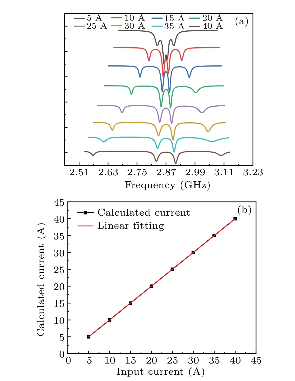
Fig.3.(a)Shift of ODMR formant frequency under different input currents.(b)The relationship between the calculated current and the actual current.
In order to evaluate the performance of the designed current sensor, we use Keysight B2962A current source, which can be used as a standard current to calibrate the output current calculated by the current sensor.We set several test points from 5 A to 40 A,and each point is the average of the data recorded ten times.In addition, we have simulated and collected 100 sets of data for the regional magnetic field of 2 mm×2 mm in the middle of the air gap,and the percentage error of the magnetic field strength data is less than 0.005%,so the position error of the diamond can be ignored.After placing the diamond in the air gap,the positions of all devices,including the wire, the diamond, the magnetic gathering ring and so on, will be fixed.And from the experimental data, it can be seen that the experimental repeatability is good,so the reading of the current sensor is stable.
The output current is calculated from the ODMR resonance frequency solution,and the linearity of input current and output current is analyzed and fitted.The results in Fig.3(b).show the relationship between the calculated current and the actual current.It can be seen that the current sensor shows a high linearity in a large working range of 5–40 A, about 33 ppm, which is much higher than the current sensors commonly used in the market.The formula for calculating the linearity is shown in the supplementary materials as Eq.(S1).And the performance of the proposed current sensor compared with other technologies is shown in Table S2 of the supplementary materials.The new current sensor designed in this paper can achieve such excellent linearity thanks to the important role of the magnetic gathering ring and diamond NV color center.On the one hand,the ring enhances the magnetic induction intensity generated by the measured current and improves the measurement sensitivity.It also eliminates the interference of magnetic fields in the environment.On the other hand,thanks to the excellent measurement performance of diamond NV color center ensemble system,quantum operation and readout can be carried out through the spin of NV color center,which can realize quantitative and nondestructive measurement of magnetic properties.Therefore,the current sensor has an approximate and low absolute error in the whole working range.
When the measuring current range is 5–40 A,the absolute error of the measuring current is less than 51µA,as shown in Fig.4(a).Equation(S2)shown in the supplementary materials is the formula for calculating the absolute error.In the current sensor,the equivalent accuracy of magnetic field measurement is better than 0.56µT.The absolute error of the current source used in the experiment and the systematic error caused by the wire placement will help to improve the performance of the designed current sensor prototype.According to experience,in this experiment, the wire is just completely placed in the inner hole of the sensor without any gap.The wire is placed in the center of the magnetic gathering ring through hole of the sensor to ensure that the position is not biased as much as possible, and the maximum absolute error of the current source used is very small and can be ignored.
Since the absolute error has no obvious change,the relative error decreases with the increase of the actual current,as shown in Fig.4(b).The relative error at 40 A is 2.42×10⁻⁶.Equation(S3)shown in the supplementary materials is the formula for calculating the absolute error.In addition, we also evaluated the performance of the current sensor through Allan variance, as shown in Fig.5.When the current is 10 A, the sampling rate is 250 Hz,and the output of the current sensor is recorded for 1 hour.The results show that the short-term stability of the sensor is lower than 0.0002 A.The value related to the average time of 10 min is consistent with the absolute error data in the preceding paragraph.
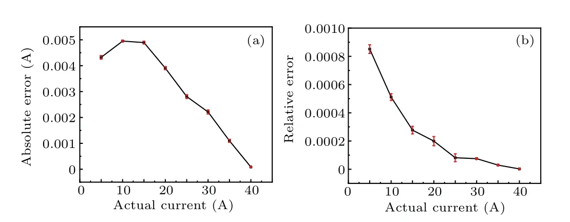
Fig.4.(a) Absolute error and under actual current.(b) Relative error under actual current.

Fig.5.Allan variance of the current sensor data.The short-term stability of the sensor is lower than 0.0002 A.
Although the preliminary experiment in this paper has achieved quite good results, there are still many details to be improved, and many other factors need to be considered and tested in future work.For example,temperature is an influential factor that almost any experiment should consider.According to the research of Shaozhuo Lin and others,[35]a modulation and demodulation technology and PID frequency locking technology are used to realize independent detection of two spin symmetry states of NV color center,the common mode cancellation method is used to suppress spin information noise caused by temperature, so as to suppress temperature noise in NV magnetometer and improve accuracy and sensitivity of NV magnetometer.At present,the dual formant system can suppress temperature noise by 10 times and this method still has a lot of room for improvement.In future experiments,this method can be combined with the current sensor based on diamond NV color center designed in this paper,so that the NV quantum sensor can be applied to a wider environment.In addition,the noise in the current should also be considered and filtered to reduce the impact on the experimental results in the future optimization experiments.The traditional method of installing harmonic compensation devices to suppress harmonics and noise can be considered,that is,using LC tuned filters.This method has a simple structure, which can compensate both harmonics and reactive power, and can meet the experimental requirements.Furthermore,we can also optimize the future experimental results from the design of the experimental device itself.For example,in order to further optimize the experimental system, we can make design choices from the shape,material,thickness,air gap size and other aspects of the magnetic focusing structure,so as to obtain better magnetic focusing effect and better experimental results.
4.Conclusion
In summary, we have designed and proved a highprecision DC current sensor based on diamond NV color center,which can maintain an ultra-high linearity in a large measurement range, as high as 33 ppm.When the range of input current is 5–40 A, the absolute error of calculated current is less than 51µA,and the relative error is 2.42×10⁻⁶at 40 A.In addition,there are other interference effects during the experiment,such as temperature,wire placement,noise of electric equipment, etc., which will have a certain impact on the experimental data.Even so, such a high measurement linearity is enough to show its outstanding performance.Compared with other current sensors,the current sensor based on optical diamond NV color center has outstanding advantages,and will have a very wide application prospect in the field of precision measurement.
Acknowledgements
Project supported in part by the National Natural Science Foundation of China (Grant Nos.51922009, 51727808,62175219, 62103385, and 51821003), the Key Laboratory of Shanxi Province(Grant No.201905D121001),and the Shanxi‘1331 Project’Key Subjects Construction.
猜你喜欢
杂志排行

Chinese Physics B的其它文章
- Interaction solutions and localized waves to the(2+1)-dimensional Hirota–Satsuma–Ito equation with variable coefficient
- Soliton propagation for a coupled Schr¨odinger equation describing Rossby waves
- Angle robust transmitted plasmonic colors with different surroundings utilizing localized surface plasmon resonance
- Rapid stabilization of stochastic quantum systems in a unified framework
- An improved ISR-WV rumor propagation model based on multichannels with time delay and pulse vaccination
- Quantum homomorphic broadcast multi-signature based on homomorphic aggregation