Real-time localization for underwater equipment using an extremely low frequency electric field
2023-09-02JiweiZhngPengYuRunxingJingTotoXie
Ji-wei Zhng ,Peng Yu ,Run-xing Jing ,To-to Xie
a College of Weapon Engineering,Naval University of Engineering,Wuhan,430033,China
b Weaponry Department,Naval Petty Officer Academy,Bengbu,233012,China
c College of Electric Engineering,Naval University of Engineering,Wuhan,430033,China
Keywords:Terms-Real-time tracking and location method Underwater equipment location ELF electric field Shallow sea Physical scale experiment Sea experiment
ABSTRACT A new real-time underwater equipment location method adopting an electric field induced by a standard current source is proposed.Our goals were real-time tracking and location of stationary or moving underwater equipment both in shallow and deep seas,under noisy conditions.The main features of this method are as follows: (1) a standard current source on the water surface,which can be towed by a vehicle,consisting of two electrodes,a signal generator,and a GPS unit;(2) measurement of the extremely low frequency(ELF)electric field emitted by the current source,made possible by electric field sensors on the underwater equipment;(3) position of the underwater equipment is estimated in real time based on a progressive update extended Kalman filter (PUEKF),which is carried out using the propagation model of an ELF electric field because the electric field at the position of the underwater equipment and the current source position are known.We verified the accuracy of our method and confirmed real-time location feasibility through numerical,physical scale,and real-time sea experiments.Through numerical experiments,we verified that our method works for underwater equipment location in real-world conditions,and the location error can be less than 0.2 m.Next,real-time location experiments for stationary underwater measuring equipment in water tank were conducted.The result shows that the location error can be less than 0.1 m.We also confirmed real-time location feasibility through the use of offshore experiment.We expect that our method will complement conventional underwater acoustic location methods for underwater equipment in acoustically noisy environments.
1.Introduction
Underwater object detection and location have been a popular and significant research area.For this purpose,a variety of techniques such as underwater surveillance systems,autonomous underwater vehicles (AUVs),along with mine and torpedo detection has been developed rapidly [1-5].Traditionally,acoustic methods have primarily been used for underwater object detection.However,acoustic methods are vulnerable to environmental conditions such as seafloor features,water depth,thermocline layer,tide speed,and composition,particularly in shallow water [6-12].Recently,non-acoustic detection techniques have been applied for this purpose.
Compared with acoustic and other non-acoustic methods,underwater electrical methods have the advantages of strong resistance to environmental noise and long propagation distance,which has recently been the focus of underwater non-acoustic detection.Due to corrosion and anti-corrosion,ships and submarines generate underwater electric field signals,and the rotation of propeller generates ELF electric field.Underwater electric field signal is an important exposure of naval vessels,which can be used for target detection,location and recognition [13,14].
And electrical methods have been applied to developing techniques of underwater surveillance nodes,networks,and mine detection.The biggest difference between electric field and sound field in the sea is that the electric field has no noise similar to reverberation.The electric field is mainly affected by the induced electric field generated by sea wave,tide,ocean current and other seawater movements.These noise levels can reach the order of μV/m underwater and 10 μV/m near the water surface.However with the increase of water depth,the movement of seawater will be weakened,as well as the noise intensity [15].
Furthermore,in order to reduce the probability of being detected,many electrically stealthy techniques have been used in practice for underwater objects,such as an active shaft grounding system,and an advanced impressed current cathodic protection system [16-18].Electric field measuring stations have also been established for the purpose of monitoring electrical power in a stealth mode in many countries.
Many applications,such as multi-physical field measurement of underwater objects,underwater object detection and location,and the need to locate measuring equipment.Accuracy,speed,and simplicity are always major challenges associated with underwater equipment location methods.Traditionally,acoustic methods have been the main techniques used for underwater equipment location,which also include inertial navigation and magnetic methods.Acoustic methods can be divided into three types: ultra-short,short,and long baselines [19,20].The ultra-short and short baseline methods are simple and easy to operate,but the absolute accuracy of a location is affected by the compass and attitude sensor of the peripheral equipment.In addition,the baseline must be more than 40 m to achieve a high-precision baseline for the methods used in deep water,and a strict calibration is also required before measurement.The underwater inertial navigation is relatively easy to implement,but with poor accuracy [21].Magnetic methods are mainly used to locate magnetic sensors,and can achieve an accuracy of±0.2 m under certain conditions;however,their accuracies are subject to interference from geomagnetic anomalies and other disturbances[22,23].Therefore,this paper proposes a new location method for underwater equipment by adopting an extremely low frequency electric field.Electrical methods have been used for underwater object tracking and location recently.These electrical methods can be divided into active and passive methods.Active methods have a detection line consisting of two current electrodes and multiple potential electrodes,and the current electrodes that output a stable electric field signal.This method detects and locates a target by analyzing the difference between the background and the subsequently measured electric field data by the use of multiple potential electrodes [24-28].The detection range of active methods can be less than 100 m depending on the target size.
Passive methods can be used to estimate the trajectory and position of the measured target by measuring the extremely low frequency (ELF) electric field radiated by the target itself and a propagation model of the ELF electric field.The target tracking and location feasibility of this method has been verified through numerical modeling and real-time sea experiments,and its tracking distance can reach as far as several hundred meters [29-31].
In the proposed method the source position and parameters are known,and the positions of the electric field measuring equipment are estimated through the ELF electric field of current source measured by the underwater measuring equipment.Because of the propagation characteristics of the ELF electric field,our method is more robust for noisy environmental conditions and cost effective,and can also be very useful in location of underwater equipment under harsh acoustic conditions,particularly in shallow water.Therefore,this method can improve underwater location strategies under various challenging conditions as a complement to conventional methods.
We expect that our method which can be employed at distances of more than several hundred meters under noisy environments can be used for a real-time locating underwater surveillance system and for tracking AUVs.To achieve this purpose,a real-time location algorithm based on a progressive update extended Kalman filter(PUEKF)was developed.In this paper,we verified the method and confirmed the feasibility of real-time location for underwater measuring equipment through numerical,water tank,and realtime sea experiments.The results of numerical experiments show that the location accuracy was less than 0.2 m in conditions with a large amount of noise.The location accuracy was around 0.1 m in the water tank experiments.In addition,the location accuracy can be less than 0.7 m in real-time sea experiments.It is particularly encouraging that the location method worked correctly in realtime sea conditions where many environmental factors varied in real time.
This paper is organized as follows.Section 2 describes the proposed method in detail.Section 3 describes the real-time location algorithm based on PUEKF.Section 4 presents the results of numerical,water tank,and real-time sea experiments.Finally,Section 5 presents a discussion and the conclusions of this paper.
2.Method
The conceptual installation of this method mainly included a standard current source,underwater measuring equipment,and a data acquisition system.The standard current source consisted of two current electrodes,a signal generator,and a GPS unit that together can be anchored at the water surface or can move along a specific course when towed by a surface vehicle.The distance between the two fixed current electrodes can be several meters,depending on the depth of the measuring equipment needs to be located;the shallower the equipment,the shorter the distance between the electrodes.When operational,the current electrodes output ELF current (DC-30Hz).The located measuring equipment or AUV have several potential electrodes (electric field sensors)used to measure the underwater electric field.
The main location process of the proposed method is as follows:
(1) A certain intensity of current is emitted into the seawater continuously by two current electrodes of the standard current source.
(2) The standard current source passes the distribution area of the underwater equipment along a certain track.
(3) The ELF electric fields generated by the standard current source are measured by the underwater equipment in real time.
(4) The position of the underwater equipment is estimated and updated in real time using the data including the ELF electric field,the position and strength information of the standard current source.In this position estimation process,the propagation model of the ELF electric field is used.
The fourth step is the core of the real-time underwater equipment location method.Therefore,this paper developed a real-time location algorithm based on PUEKF.
2.1.Location algorithm
2.1.1.Location model
The state equation and observation equation can be described as follows:
Generally,the depth of the underwater equipment is easy to obtain through the depth sensor,so the state of the underwater equipment which needs to be estimated includes horizontal position inx-andy-directions,and if the equipment is moving at a speed of v =(vx,vy),the state should include v also.So the state vector of the underwater equipment is expressed as
where,(xk,yk)is the horizontal position at timek,(vx,k,vy,k)is the speed at timek.If the equipment is stationary or its speed is known,the state vector can be simplified as
furthermore,if multiple targets need to be located simultaneously,the state vector can be expressed as
where,(,) is the horizontal position of equipmentiat timek,i=1,2,…n,andnis the total number of underwater equipment.
Obviously,the transition between state xk-1and xkis linear,so Φ is a state transition matrix in Eq.(1) which can be expressed as
According to the electric field model of horizontal electric dipole[32],the static electric field generated by the standard current source can be expressed as
dis seawater depth,his the depth of current source,η =(σ-σ1)/(σ+σ1)is seabed reflection coefficient,σ1is seafloor conductivity,σ is seawater conductivity,nis the number of mirroring(reflection)layer,and its reasonable ranges are 10-20 in the actual calculation,(x,y,z) is the location of measuring equipment,(x0,y0,h)is the location current source,andIis the current of current source,dlthe distance between two electrodes.
Let the attitude angle of theith underwater equipment be αi,βi,and γi;then the electric field measured by the underwater equipment projected from the electric field signal to the north-east geodetic coordinate system is
where,Aiis the attitude transformation matrix of theith measuring equipment,expressed as
So the observation of the underwater equipment is
We can know from Eq.(7) -Eq.(9),and Eq.(11) that the observation model of the underwater equipment is a nonlinear model,so the nonlinear filter method should be used for the location method.
2.1.2.Location method based on PUEKF
Many Kalman filtering methods exist for nonlinear models,such as the extended Kalman filter(EKF),unscented Kalman filter(UKF),volume Kalman filter [33],each of which has its own specific applications.Researchers who study the ship electric field target positioning method have shown that PUEKF can achieve better results in electric field tracking[29].Therefore,it is feasible to apply the PUEKF method to locate underwater electromagnetic measurement devices.
The traditional Kalman filter adopts one-step observation update.The idea of progressive Bayes is to insert pseudo time series and gradually introduce observation information to solve the problem of too narrow EKF likelihood function.PUEKF is a new nonlinear filtering algorithm based on the progressive updating idea of progressive Bayes and extended Kalman filter.The focus of PUEKF is to redesign the observation update,dividing the time interval[tk-1,tk]intoNpusub intervals,and the time interval of each sub interval is δλ =(tk-tk-1)/Npu,which is also called asymptotic factor.This is equivalent to insertingNpu-1 pseudo time series into [tk-1,tk]and obtaining n observations in sequence.The observation update process is carried out once in each sub interval.
The key steps of PUEKF algorithm are.
1) Time update
where,Pk|k-1is covariance matrix.
2) Observation update
3.Underwater equipment location experiment
As a simplification in the experiments,we assumed that two measuring equipment nodes needing to be located are stationary on the sea floor.In numerical,water tank,and real-time sea experiments the horizontal component of electric field are taken as the observation of each measuring node,and two measuring nodes are located simultaneously.The feasibility of locating only one measuring node was also confirmed in water tank experiments.In this section,we verified the location method and confirmed the real-time feasibility of locating underwater equipment through numerical,physical scale,and real-time sea experiments.
3.1.Numerical experiments
The basic numerical experiments parameters were established as shown in Table 1.
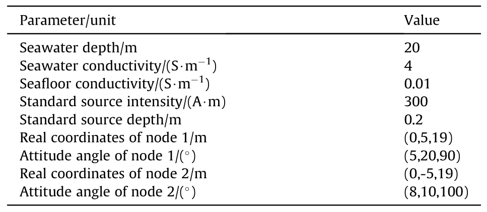
Table 1Basic parameters of numerical experiments.
Taking the observation noise variance matrix as ((μV/m)2)
the initial covariance matrix is (m2)
The initial position coordinates of the two measuring devices were taken as (50,50,19) m and (50,-50,19) m where the initial position error was about 60 m,and the peak-to-peak value of the environmental electric field is 1 μV/m.Without taking into account the attitude error of the measuring device and the trajectory error of the current source,Fig.1 shows the location process,and Fig.2 shows the real-time location error which is defined as the estimated value minus the real value.

Fig.1.Top view of the location process.The current source is moving on the surface of the area above the measuring device during the location process.

Fig.2.Real time location error.The horizontal location error decreases over time and eventually converges to a very small value about 1 cm.The location method is verified as working for underwater equipment location.
In addition,in order to test the robustness of the algorithm against the environmental noise,attitude error,and trajectory error of the current source,the numerical experiments were analyzed individually.In the analysis,the location error in a certain direction is defined as
whereMC=100 is the number of simulations,is the actual position of the measuring device in a certain direction,xis the estimated position,Errorxis the location error in directionx,andErroryis the location error in directiony.
Because the environmental noise on the seafloor of a shallow sea offshore can be up to the order of μV/m and can be tens μV/m on moving platforms,the peak-to-peak values of environmental noise was taken as 1 μV/m,10 μV/m,30 μV/m,and 50 μV/m in the analysis of the influence of environmental noise.Table 2 shows the location error under the conditions of four levels of environmental noise.

Table 2Location error with four levels of environmental noise.
We can see from Table 2 that when the level of noise increases from 1 μV/m to 50 μV/m,the location error increases because of the decrease of the signal-to-noise ratio.The maximum error is 0.133 m and 0.795 m in thex-andy-directions,respectively.The minimum error is 0.002 m and 0.007 m inx-andy-directions,respectively,when the environmental noise was less than 1 μV/m.
Usually,the accuracy of an attitude sensor can be less than 0.1°.So the attitude errors were taken as 0.1°,0.3°,0.5°,and 1.0°for the attitude errors analysis.Table 3 shows the location error under the conditions of four different attitude errors.
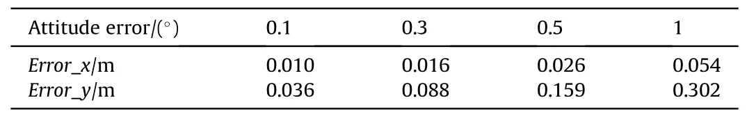
Table 3Location errors with four different attitude errors.
Table 3 shows that the location error will increase with an increase of the angle error of the attitude sensor.When attitude error was less than 1°,the location error inx-direction was less than 0.1 m,and when it was less than 0.5°,the location error in the ydirection was less than 0.2 m.Therefore,an attitude sensor with an accuracy of 0.1°can meet the requirements of this location methods.
The standard current source trajectory error is mainly caused by a discrepancy between the recorded and actual position of the current source,which might have a certain impact on the location results.The random trajectory errors with peak values of 0.5 m,1 m,2 m and 5 m ware taken into account,because the accuracy of differential GPS can reach the 1 cm level.Table 4 shows the location error under the conditions of four different source trajectory errors.
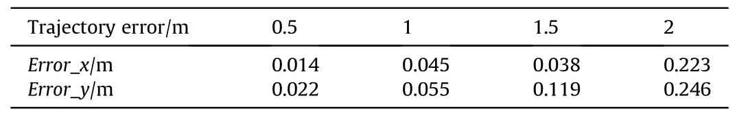
Table 4Location error with four different trajectory error.
We can see from Table 4 that when the trajectory error was less than 1.5 m,the location error was less than 0.2 m.
In consideration of the actual conditions,the three main types of errors were taken into account simultaneously,where the peak-topeak value of environmental noise was 10 μV/m,the attitude sensor accuracy was 0.5°,the standard current source trajectory error was 0.5 m,and with other parameters remained unchanged.Fig.3 shows the real-time location error under those noise levels.
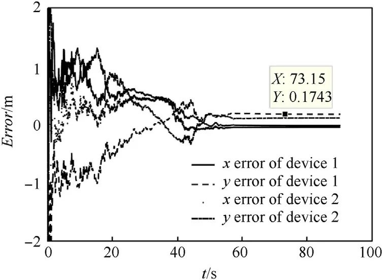
Fig.3.Real time location error in actual conditions.The horizontal location error decrease over time and eventually converged to a very small value less than 0.2 m.This confirmed that the location method was working for underwater equipment location in actual conditions.
3.2.Water tank experiments
For the physical scale experiments,a glass-reinforced plastics water tank,500 cm wide,800 cm long,and 150 cm deep,was set up(Fig.4).The water tank was filled with seawater with conductivity of 0.39 S/m.An automatic three-axis gantry system was installed over the water tank to move the current source in the tank.

Fig.4.Photograph of the instrument and water tank,in a laboratory.The data processing unit was operated using a laptop computer.
In order to reduce problems with corrosion and improve the current output capacity,cylindrical electrodes made with mixed metal oxides having a diameter of 3 cm and a length of 0.5 cm were used as the two current electrodes of the standard current source.The two current electrodes were fixed to an epoxy resin stick at a distance of 10 cm;next,the epoxy resin stick was placed 10 cm underwater and fixed to the gantry (Fig.5(a)).The underwater measuring equipment was represented by two electric field measuring nodes,each consisting of four Ag/AgCl potential electrodes,which were arranged in orthogonal pairs,spaced 15 cm apart,to measure the horizontal component of the electric field(Fig.5(b)).The measuring nodes were positioned on the bottom of the water tank.
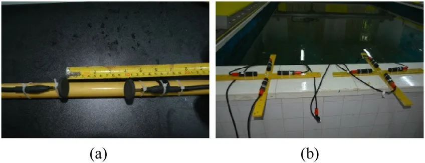
Fig.5.Electrodes and measuring nodes: (a) Electrodes of current source;(b)Measuring nodes consisting of four Ag/AgCl potential electrodes.
The experimental configuration is shown in Fig.6.The real position of the measuring nodes were (-0.02 m,-0.3 m;defined as node 1)and(0,0.4 m;defined as node 2).The current source moved along thex-axis with a velocity of 5.7 cm/s.The data sampling rate was 250 Hz,and the current source was set to 1 A(DC).In the real time location algorithm,the initial positions of the measuring nodes were set as(0.5 m,-2 m)and(0.5 m,2 m),so the initial error was about 2 m,and the observed noise variance matrix was the actual measured environmental noise ((μV/m)2)

Fig.6.Plan view of the physical scale experiments.The electrodes move along the center line of the water tank.
Fig.7 shows the results of the physical scale experiments.The root-mean-square error(RMSE)of the location was calculated 20 s after the starting location was reached,because at that time the location errors tended to be stable.Table 5 shows the location errors of the physical scale experiments which were less than 0.1 m.Through the physical scale experiments,we have verified that our method can be applied to underwater equipment location in physical situations and the developed location algorithm works correctly.
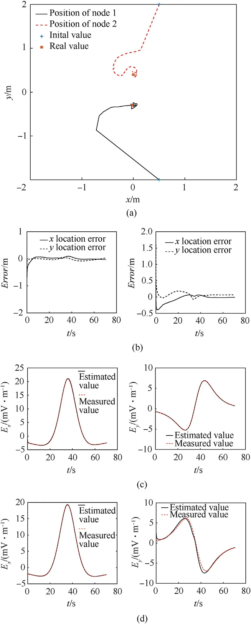
Fig.7.Results of the physical scale experiments:(a)The changing process of estimated position;(b)The real time location error;(c)The measured electric field of node 1;(d)The measured electric field of node 2.(a) and (b) show the estimated position and location error,which converge rapidly to the true position over time;(c) and (d) are the measured electric field compared with the electric field calculated using the estimated position of the two measuring nodes.
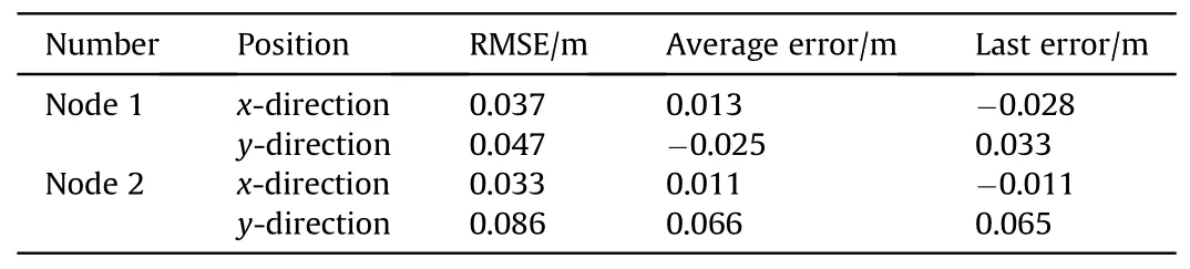
Table 5Location errors of the physical scale experiments.
To further analyze the robustness of the location method to initial values,the different initial values were set for the location algorithm.Using the data of physical scale experiments,the results are shown in Table 6.
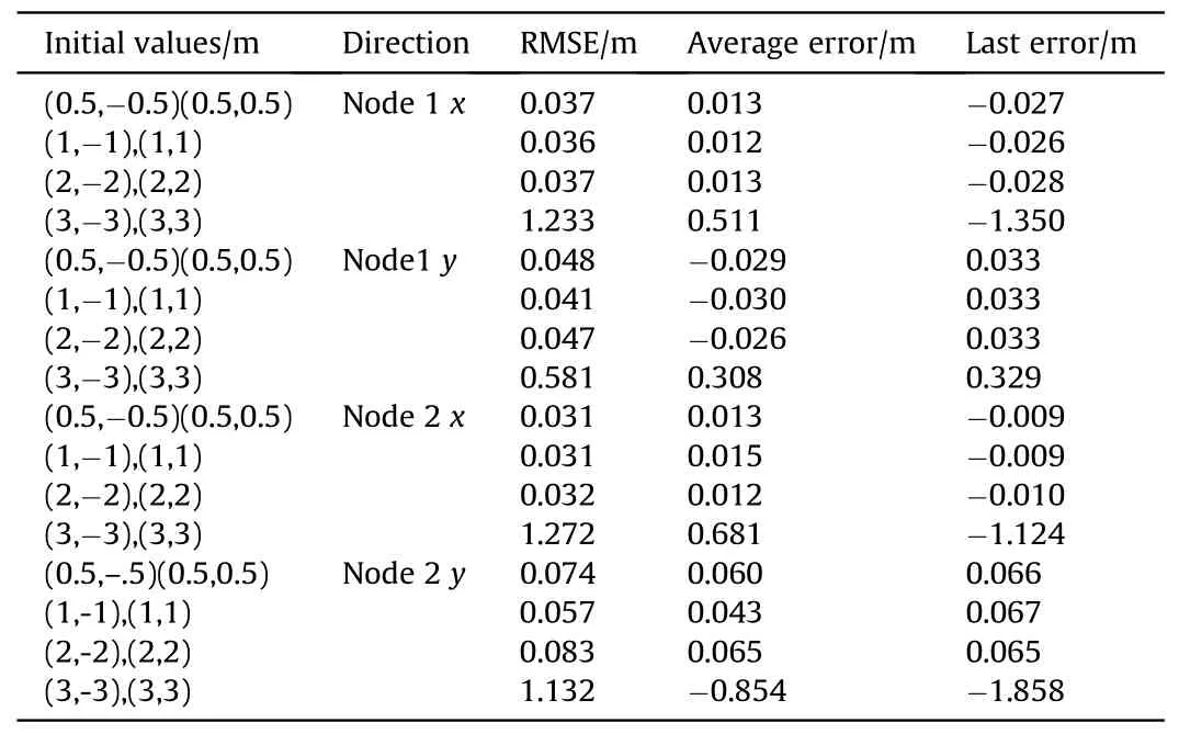
Table 6Location errors with different initial values of the physical scale experiments.
From Table 6,we found that the location errors of our method were less than 0.1 m in a certain initial value errors(less than 3 m),but will increase rapidly when the initial value error is too large(more than 4 m).
We also analyze the feasibility of locating a single node at one time.Taking node 1 as an example,the initial position was set as(0.5,-2) m.The observed noise variance matrix was ((μV/m)2):
Fig.8 shows the results of locating node 1.Table 7 shows the location errors of node 1.
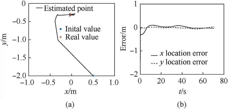
Fig.8.Results of locating node 1:(a)The changing process of the estimated position of node 1,which is rapidly approaching the real value;(b) Location error,which converges rapidly to a small value around 0 over time.
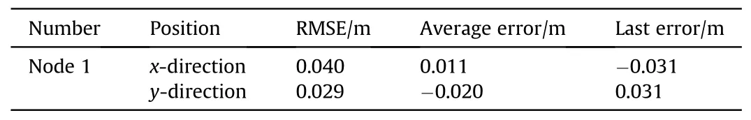
Table 7Location errors of node 1.
By comparing Table 6 and Table 7,we can see that it is feasible to locate two nodes simultaneously and locate one node independently with the same accuracy.
In the water tank experiments,the measuring equipment was stationary and positioned on the bottom of the water tank,but if the measuring equipment is moving or shaking in the water,the electric field measured by the equipment will be seriously disturbed,which would increase the location error.An effective solution to this problem is to set the current source to output an ELF current whose frequency is different from the interference noise frequency,so that the envelopes of the ELF electric field can measured by underwater nodes that are used in the location algorithm.This method is feasible because the envelope of the ELF electric field is basically the same as the waveform of the static electric field induced by the DC current.
3.3.Real-time sea experiments
To verify the feasibility of the proposed method,an experiment has been conducted at sea.The test area had a seawater depth of 9 m,a seawater conductivity of 3.6 S/m which was measured by a conductivity meter,and the seafloor conductivity was taken as 0.03 S/m.The sea state was lower than level II during the experiment.
A signal generator and a GPS terminal were placed on a glassreinforced plastic boat.Mixed metal oxide cylinders with a diameter of 10 cm and a length of 15 cm were used as the two current electrodes of the standard current source towed behind the boat(Fig.9).The trajectory of the current source was roughly acquired using a real-time-kinematic GPS unit whose accuracy is about 3 m in single point mode and 3 cm in RTK (real-time kinemati) mode mounted on the boat moving at a speed of about 2.5 m/s.The depths of the current electrodes were set to 0.2 m,and the distance between the two current electrodes was 14 m,the current was set to 10 A,with a frequency of 3 Hz since the measuring equipment was floating on the surface,as discussed in the previous section;therefore,the DC current would be disturbed by the shaking of the measuring nodes.

Fig.9.Current electrodes are towed behind the boat.
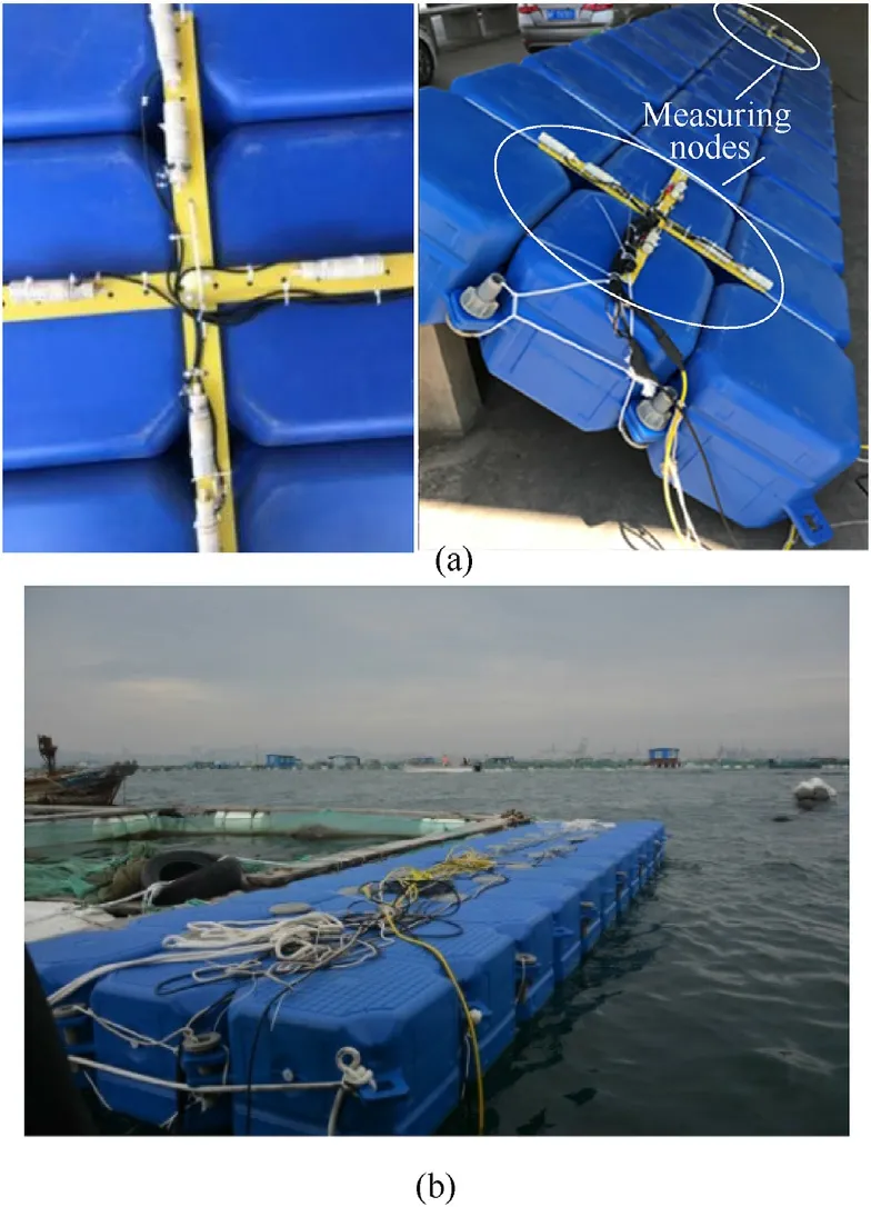
Fig.10.Measuring devices and the plastic raft:(a)Two electric field measuring nodes.Four Ag/AgCl potential electrodes used as the sensors of each measuring node;(b)Plastic raft fixed near the channel.Measuring nodes were positioned on the bottom of the plastic raft fixed near the channel.
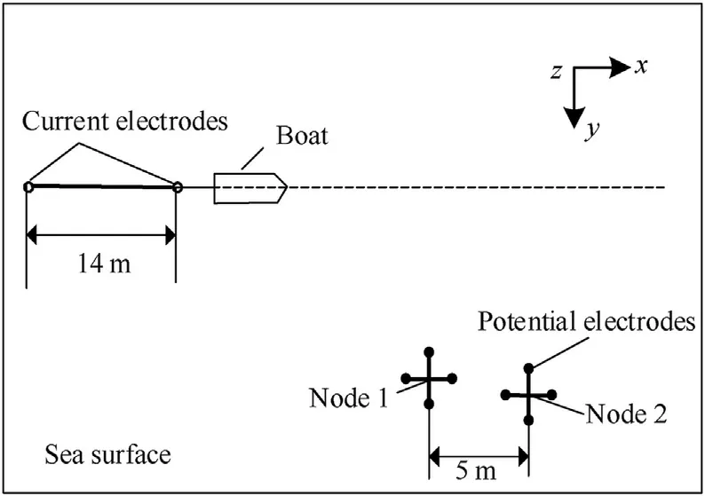
Fig.11.Plan view of the real-time sea experiment.The moving direction of the current source is defined as the x-axis.The measuring nodes were floating near the channel.
The latitude and longitude of the two measuring devices measured by GPS were (37.58839426°N,121.42320001°E) and(37.58835645°N,121.42321723°E).All GPS latitude and longitude coordinates were converted into a geodetic coordinate system via WGS84,and the location algorithm was performed in the geodetic coordinate system.The trajectory of the standard current source is shown in Fig.12(a),which was converted into the geodetic coordinate system,and the moving direction of the standard current source was taken as thex-axis(Fig.12(b)).The positions got by the GPS of the two measurement nodes are(-67.6,38.6)m and(-63.2,39.5)m.Thus the distance between the two measurement nodes is approximately 4.5 m,whereas the actual distance is 5 m;therefore,the GPS positioning error is about 0.5 m after 3 min accumulative average.
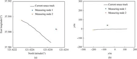
Fig.12.Trajectory of the standard current source: (a) Latitude and longitude of the Trajectory;(b) Trajectory in the geodetic coordinate system.
The results of the real-time experiments are shown in Fig.13.The location errors are shown in Table 8.The RMSE and average location error were calculated 70 s after leaving the starting location,because at that time the location errors tend to be stable.
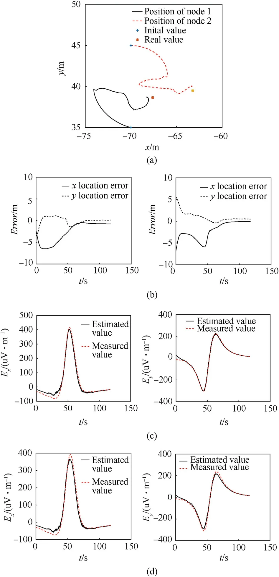
Fig.13.Real time location errors of electric field measuring nodes.(a) The change in the estimated position;(b)The real time location error;(c)The measured electric field of node 1;(d) The measured electric field of node 2.Initial values of the two nodes were(-70,35) m and (-70,45)m.The measured value in(c) and (d) are the envelope of the ELF electric field.

Table 8Location errors of the real-time sea experiments.
The results show that the location errors converge to a small value when the current source is close to or passing the nodes.In addition,the RMSE and average location error were less than 0.7 m,which are larger than the results of the water tank experiments.
The main reasons for the increase in the location error when compared with that of water tank experiments include the following.
(1) The real positions of the two measuring nodes have positioning errors within 0.5 m,because of the positioning error of GPS.
(2) The attitude change of the measuring node is ignored in the experiment.The measuring nodes were fixed on the floating raft (Fig.10),which would be shaking by the waves.The ignoring of attitude leads to the attitude angle error mentioned in the previous section,which will increase the location error as indicated in numerical experiments.
4.Discussion and conclusions
We propose a new real-time underwater equipment location method adopting an electric field induced by a standard current source.The final goals of this method are real-time tracking and location of underwater stationary or moving equipment both in shallow and deep sea,under noisy conditions.For this purpose,a real-time location algorithm based on PUEKF was developed.We verified the accuracy of our method and confirmed the feasibility of using real-time location data through numerical,physical scale,and real-time sea experiments.
In the numerical experiments,the feasibility and robustness of our method were verified.We found that the horizontal location error decreased over time and eventually converged to a very small value less than 0.2 m;when peak-to-peak value of environmental noise was 10 μV/m,the attitude sensor accuracy was 0.5°,the standard current source trajectory error was 0.5 m.
In the water tank experiments,two static underwater measuring nodes were located by our method in a glass-reinforced plastic water tank that was 500 cm wide,800 cm long,and 150 cm deep.The robustness of the location method to initial values was also analyzed.The results of the water tank experiments are as follows.
(1) The estimated position of measuring node converges rapidly to the true position over time.
(2) The location errors of this method are less than 0.1 m in a certain initial value errors (less than 3 m).In practical application,the position where the device is placed into the water can be used as the initial value of the location algorithm to reduce the initial value error.
(3) The proposed location algorithm can locate one or more targets simultaneously with the same accuracy.
(4) When locating moving equipment,the envelope of the ELF electric field can be used in the location algorithm to avoid the interference noise induced by shaking and sea waves.
In the real-time sea experiment,comprehensive verification of the proposed method and system were carried out.Mixed metal oxide cylinders with a diameter of 10 cm and a length of 15 cm were used as the two current electrodes of the current source were towed by a boat at the speed of 2.5 m/s.The underwater measuring equipment was represented by two electric field measuring nodes,each consisting of four Ag/AgCl potential electrodes,and the measuring nodes were positioned on the bottom of a plastic raft fixed near the channel.The RMSE and average location error were less than 0.7 m,which were larger than the data from the water tank experiments because of the GPS error,latitude error,and so on.
Future studies should focus on locating the moving underwater measuring equipment such as an AUV,and we will try to reduce location error to 0.2 m by improving the experimental system,and carrying out additional real-time sea experiments.We expect that the proposed method can complement conventional underwater acoustic location methods for underwater equipment in acoustically noisy environments,and would be a good solution for underwater equipment for various purposes.
Declaration of competing interest
The authors declare that they have no known competing financial interests or personal relationships that could have appeared to influence the work reported in this paper.
Acknowledgements
This work is supported by the Youth Foundation of the National Natural Science Foundation of China(Grant No.51509252).
杂志排行
Defence Technology的其它文章
- Deep learning-based method for detecting anomalies in electromagnetic environment situation
- Impact point prediction guidance of ballistic missile in high maneuver penetration condition
- Numerical simulation of flow field characteristics and theimprovement of pressure oscillation of rotating detonation engine
- Comparative investigations of ternary thermite Al/Fe2O3/CuO and Al/Fe2O3/Bi2O3 from pyrolytic,kinetics and combustion behaviors
- Adaptive saturated tracking control for solid launch vehicles in ascending based on differential inclusion stabilization
- The dynamic response of a high-density polyethylene slow-release structure under launching overload