Ballistic tests on hot-rolled Ti-6Al-4V plates: Experiments and numerical approaches
2023-09-02AlexnerJnBenjminJmesRlphDemrtyMrelSorgerStefnEenuerAuePrestlIngoSillerMrtinStokingerHelmutClemens
Alexner Jn ,Benjmin Jmes Rlph ,Yël Demrty ,Mrel Sorger ,Stefn Eenuer ,Aue Prestl ,Ingo Siller ,Mrtin Stokinger ,Helmut Clemens
a Department of Materials Science,Montanuniversität Leoben,Franz Josef-Straße 18,8700 Leoben,Austria
b Department Product Engineering,Montanuniversität Leoben,Franz Josef-Straße 18,8700 Leoben,Austria
c French-German Research Institute of Saint-Louis,5 Rue du Géenéral Cassagnou,68300 Saint-Louis,France
d voestalpine BOEHLER Bleche GmbH & Co KG,Boehler-Gasse 1,8680,Mürzzuschlag,Austria
Keywords:Ti-6Al-4V Ballistic performance Split Hopkinson pressure bar FE simulation Adiabatic shear bands Intermetallic phase
ABSTRACT Superior ballistic performance and the lightweight character of Ti alloys are considered as main reasons for their use in armour applications against a broad spectrum of ballistic threats,e.g.bullet,fragment or blast impact.Because dynamic loading caused by typical penetrators is characterized by high strain rates,only specific test methods allow a closer investigation of the respective material behaviour.In the present study,quasi-static and dynamic compression tests as well as ballistic tests were conducted on a twophase α+β alloy Ti-6Al-4V (in m%) manufactured by hot-rolling.Post-deformation heat treatments,influencing microstructure and mechanical properties were applied in order to compare three different microstructural configurations: as-rolled,mill-annealed and bimodal.While,on the one hand,ballistic tests were employed for the determination of the ballistic limit velocity v50,compression tests,on the other hand,delivered essential input parameters for the application of the Johnson-Cook constitutive model in a finite element simulation of the impact event.The comparison of experimental results to simulation results was supplemented by means of microstructural characterization of tested samples with the focus set on the prevalently observed deformation and damage mechanisms,as for example adiabatic shearing.
1.Introduction
Titanium alloys offer an attractive combination of mechanical properties and low density.Especially by the development of socalled α+β alloys,a material class was established that exhibits high specific strength as well as high fracture toughness,together with good hot-formability and improved ductility.This wide spectrum of properties,related to high material costs,justifies the employment of α+β alloys in a variety of high-performance applications,for example,in aerospace,motor sports or also in the defence sector [1-5].As hot-rolling provides an efficient way for manufacturing α+β alloy products,plate material is frequently used in ballistic armour constructions[6-8].It is,for example,reported by Refs.[6,9]that the use of Ti can lead to weight reduction in the range of several tons for specific military vehicles.However,the strain rate sensitivity of Ti alloys limits the correlation between conventional mechanical properties and ballistic performance[10,11].Therefore,in order to investigate ballistic performance and impact behaviour,alternative test methods have to be taken into account.
Ti-6Al-4V is considered as the most frequently used α+β alloy[1,3,12].Even though its microstructure-property relationship in the quasi-static regime counts as already well-studied,less data exist for the high strain rate regime(>103s-1).While ballistic tests require a large amount of material and an elaborate infrastructure,a common way to overcome these problems is the application of mechanical tests at high strain rates.For example,the Split Hopkinson pressure bar (SHPB) test gives opportunity to examine tensile,compression and torsion behaviour under dynamic loading.The upper limit of strain rate is depending on the sample type and on the utilized SHPB device but typically is in the order of 103-104s-1[13].Furthermore,dynamic testing is applied to generate input parameters for material models,which describe plastic deformation beyond the quasi-static regime.
Two specific deformation mechanisms which are observed in Ti-6Al-4V during ballistic impact are the formation of adiabatic shear bands (ASBs) [14,15]and mechanical twinning [16].ASBs can be understood as regions,where localized strain occurs due to missing heat dissipation into the surrounding microstructure.Plastic deformation starts along zones which are mechanically preferred in the moment the load gets applied.When heat of deformation is not transported away fast enough from these zones a chain reaction is triggered,due to thermal softening,which acts as a locally competing mechanism to strain rate hardening during dynamic testing [17,18].Thus,the already deformed areas are even more preferred to further deformation.Ti-6Al-4V is predestined for ASB formation[6,19]due to its high volume fraction of α phase(>90%).In addition,α-rich Ti alloys are among metals of lowest thermal conductivity [1]and exhibit local crystallographic anisotropy.Twinning as a consequence of deformation,i.e.mechanical twinning,of Ti-6Al-4V was previously studied by numerous authors and it has been reported to occur in dependence of several parameters.While Lütjering et al.[1]have claimed that mechanical twinning in Ti-6Al-4V is unlikely to occur at conventional loading conditions,other studies [20,21]have shown that at certain strain rate,deformation mode,temperature or in the presence of a crystallographic texture,twinning is more pronounced during plastic deformation.Also the specific chemical composition according to standards,such as the ASTM B265 [22],has an influence on the tendency to mechanical twinning,or more exactly,a high Al and O content make twinning less probable to occur[1].However,at high strain rates,mechanical twinning is typically observed as a deformation mechanism also accounting for strain localization [23,24].
The alloy Ti-6Al-4V offers a wide range of adjustable microstructural modifications,which implies that mechanical properties can be altered respectively.Varying the microstructural morphology leads to a change of the plastic deformation behaviour and occurring damage mechanisms [1]and its influence on the ballistic performance is studied in this work.Precisely,in the present study,the material is investigated in three microstructural conditions: as-rolled (AR),bimodal after air cooling (AC) and millannealed after furnace cooling (FC).Each of them are subjected to stress relief annealing as a final heat treatment step.Microstructural characterization is conducted on the three grades as well as mechanical testing in quasi-static regime at different temperatures and dynamic compression tests at strain rates of up to 2000 s-1so as to assess the material temperature and strain rate sensitivity.Ballistic tests are also performed to quantify the ballistic limit and study the effect of the microstructural properties on the ballistic performances.In order to allow numerical design of protective systems with the developed materials,a numerical model has to be implemented.The finite element (FE) simulation is built on the basis of the Johnson-Cook (JC) constitutive model.This empirical model,which is based on experimental observations rather than on physical or mechanical principals,is selected in the present study for its simplicity and as a first approach.Resulting limitations,however,are summed up in the work of I.G.Crouch [6]such as dynamic strain ageing[25]the appearance of texture anisotropy or the formation of intermetallic phases(IMP)during ballistic impact,are not taken into account.Experimental results from ballistic limit tests are compared to numerical results both derived for hot-rolled Ti-6Al-4V plates.An in-depth characterization of thermomechanical and damage mechanisms in post-mortem tested SHPB samples and impacted plates is done in the aim to evaluate the influence of microstructural phenomena on dynamic mechanical response of the materials.It should be pointed out that in the present work the combination of applied methods,i.e.ballistic tests,microstructural characterization and a numerical approach,allows the interpretation of the results from several viewpoints.For example,the background of the observed impact mechanisms,such as the formation of a molten phase due to a eutectic reaction between bullet core and protection plate,can be explained.Additionally,approaches in literature,which estimate the temperature in dynamically deformed regions of Ti-6Al-4V,are supported[17,19].
2.Materials and methods
2.1.Material and microstructures
For all conducted experiments a hot-rolled Ti-6Al-4V alloy according to Ref.[22]was subjected.The material was manufactured to a plate geometry of 21.6 mm thickness via hot-rolling in terms of a mixed β/α+β thermo-mechanical processing route.This implies that a pre-deformation step in the single β phase field region was conducted prior to rolling in the α+β two-phase field region,i.e.below the beta transus temperatureTβ.Post-deformation heat treatments were applied to the plate material in order to adjust microstructure and mechanical properties.In the last processing step a stress relief annealing was conducted on all samples.From the heat treated material,ballistic target plates of the size 430 × 430 × 21.6 mm3were prepared via water jet cutting and cylindrical samples for SHPB testing of 6 mm height and 6 mm diameter were machined through electrical discharge machining.For further investigation of the observed eutectic transformation between the as-rolled Ti-6Al-4V alloy and the steel bullet core both materials were machined to cylindrical samples of 5 mm height and 5 mm diameter.
2.2.Microstructural characterization
For microstructural characterization,samples were determined before to as well as after the mechanical tests.Characterized starting material was taken from a representative area of the respective plates,i.e.of hot-rolled Ti-6Al-4V in AR (as-rolled microstructure),AC(bimodal/duplex microstructure)and FC(millannealed microstructure) condition.SHPB sample surfaces were determined perpendicular to the compression axis and crosssections of the penetrated areas were prepared for the examination of the ballistic impact.The metallographic preparation for SEM(scanning electron microscope)examination was done consistently according to Fleißner et al.[26],whereas etching with Kroll’s reagent[27]was conducted for light-optical microscopy(LOM)based characterization.The utilized LOM was of type Axio Imager M2 by Zeiss.For electron microscopy two devices were employed.Imaging and (energy dispersive X-ray spectroscopy) EDS analysis were conducted on a Clara SEM (Tescan) equipped with an X-MAX detector by Oxford Instruments plc.,while electron backscatter diffraction (EBSD) analysis was performed on a Thermo Fisher Scientific Versa 3D DualBeam microscope equipped with an EDAX Hikari-AXS EBSD detector.EDS was applied for a qualitative chemical analysis of the observed IMP by means of selected spotmeasurements.In order to relate strain hardening to microstructure and modelled impact stress,a Qness Q60A+micro hardness tester from ATM Qness was utilized.
In order to study the eutectic reaction between the 100Cr6 bullet core and the Ti-6Al-4V alloy a diffusion experiment towards melting temperature was performed in a dilatometer (DIL 805 A from TA Instruments).Therefore,the circular faces of two cylindrical samples (100Cr6 and Ti-6Al-4V) diameter were aligned parallel and brought into direct contact to each other providing a joint diffusion plane.Each sample had a height and a diameter of 5 mm and the contact surfaces were grinded to grit size 2000 prior to the experiment.Samples were held together by the preload(~20 N) present between the two SiO2stamps.By heating up the pair of cylindrical samples at a heating rate of 0.5°C/s under vacuum the melting point of the diffusion couple was reached when a spontaneously change in the sample length occurred.The temperature control was based on the temperature measurement via thermocouple of type S(PtRh to Pt)and the measurement spot for temperature was located on the curved cylinder surface of the Ti-6Al-4V sample closer than 1 mm to the contact plane,realized via spot-welding.The applied dilatometer setup is schematically illustrated in Fig.1.
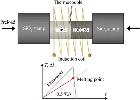
Fig.1.Schematic illustration of the dilatometer setup applied for melting experiments on the contact plane between Ti-6Al-4V and 100Cr6.With this setup the melting temperature in the interface could be determined (see text for further details).
2.3.Mechanical testing
2.3.1.Measurement of density and elastic properties
The density of the three grades has been measured using a geometrical method.The 6×6 mm2cylindrical samples have been weighted with a precision scale.Dimensions were measured using a Vernier caliper.A simple calculation of the mass divided by the sample volume provided the density.
The evaluation of elastic constants has been performed using an ultrasonic OLYMPUS 45 MG device.Based on the measurement of longitudinal and transversal wave propagation speeds,the Young's modulus,shear modulus and Poisson's ratio can be calculated following relations given in Ref.[28].Table 1 provides the measured densities and elastic constants.

Table 1Measured density and elastic properties of the three titanium alloy grades.
2.3.2.Quasi-static compression tests
Mechanical properties of produced titanium alloys were assessed under compression in quasi-static regime using an INSTRON 5985 250 kN universal testing machine.Force levels were recorded via the loading cell of the device whereas the displacement is measured by an axial clip-on extensometer fixed on the compression platens.In order to study the sensitivity of the material to strain rate,two conditions were characterized:0.001/s and 0.1/s,at room temperature.The influence of temperature was also evaluated.A thermostatic chamber MTS AEC 14×17×32 allows to characterize the three titanium alloy grades at 100°C and 200°C.A thermocouple was placed onto the specimen to control the temperature at the very beginning of the test and to check its stability during the test.To lubricate the samples and minimize barrelling,petroleum jelly was used at room temperature and copper grease at elevated temperatures.Three samples per condition were tested so as to check the experiment repeatability.
The true stress-true strain material response was obtained following the procedure described in Ref.[28]by applying a compliance correction to take into account the machine stiffness.
2.3.3.Dynamic compression tests
In order to reach higher strain rates,a SHPB setup was used.It was composed of three elements: a striker,one input bar and one output bar.All these elements were made of W720 Böhler high strength steel and their dimensions are provided in Table 2.Strain gages assembled in a full Poisson bridge allowed the measurement of propagated elastic waves:incident εi(t)and reflected εr(t)waves along the incident bar,and transmitted εt(t)wave along the output bar.An amplifier and a digital oscilloscope allowed to amplify and record the associated signals.The striker speed was measured with two photodiodes.All the tests were conducted at room temperature.As for the quasi-static tests,petroleum jelly was applied at the interfaces between bars and sample.Three samples were tested per condition.Two average strain rates were considered for these experiments around 600 s-1and 2000 s-1.Raw data were processed using a custom-made program implemented in MATLAB and using equations defined in Ref.[28]so as to plot the true stress-true strain curves.Dispersion and inertia effects were taken into account in this process.

Table 2Split Hopkinson Bar setup features.
2.4.Ballistic tests
Ballistic tests were conducted in accordance with the requirements of VPAM test level 9 certification on Ti-6Al-4V ballistic impact plates [29].This implies that projectiles of the type .308 Winchester with full metal jacket(CuZn),pointed bullet type,steel hard core (100Cr6),and Pb primer were used.The distance from barrel to target was 10±0.5 m and the impact angle was 90°,which is the angle between flight direction,i.e.the length axis of the projectile,and the attacked surface.The temperature in the test facility,as well as of tested samples prior to impact,was room temperature (RT).With a distance between single impacts of 70 mm from each other and a minimum distance of 60 mm from the plate edge,23 impacts could be performed on each Ti-6Al-4V plate.The experimental setup is shown schematically in Fig.2.In order to conduct a v50ballistic limit calculation the impact velocity was varied around the estimated critical velocity which was necessary for full perforation.The aforementioned experimental parameters were kept constant,except of the temperature,which is expected to increase locally during the event of impact.The v50value is determined statistically from generated test data according to Ref.[30]and is defined as the velocity at which the perforation probabilitypvis 0.5.The statistical model behind the calculation ofv50assumes a normal distribution between velocity and perforation probability which,however,is not always the case.When the specific damage mechanism changes over bullet velocity,a deviation from the typical“S-like”shape of pv=f(v)is usually obtained.To give an example of such behaviour,the so-called shatter-gap phenomena [6,9]might be mentioned,which can lead to two or more ballistic limit values within one experiment,i.e.within one pvgraph.It is reported,that in case of the shatter-gap one or more velocity ranges can exist in which a decreased impact velocity does enhance bullet shattering due to changes in strain rate dependent strengthening and damage mechanisms.However,for the investigated target/projectile combination of Ti-6Al-4V/.308 Winchester no such effects are expected.The velocities applied during ballistic tests were in the range from 829 to 907 m/s.Therefore,it must be noted that in the course of a ballistic limit testing the nominal bullet velocity of 820±10 m/s of test level 9[29]was exceeded.The modelled penetration depth could be compared to the real penetration depth by measuring depth from bullet crater tip to the undeformed surface of the Ti-6Al-4V plates.

Fig.2.Schematic illustration of the experimental setup of the ballistic tests conducted on Ti-6Al-4V plate material.
In order to validate the comparison between real ballistic tests and FE model high-speed videos of the impact event were taken by employing a Phantom v2512 camera equipped with a Nikon 60 mm/2.8 F macro objective.At a resolution of 256×256 a frame rate of 206 300 fps was achieved and distance from lens to impact was 1.15 m.
2.5.FE simulation
In order to receive an accurate FE model under special consideration of computational efficiency,a quarter symmetrical 3D geometry was built up.The resulting assembled model,which was created in Abaqus CAE,consists of three parts:i)the core and shell,which was set up as on part with two different sections(CuZn10 for the shell and 100Cr6 for the bullet);ii) the primer (pure lead);iii)the plate(Ti-6Al-4V).All parts were defined as deformable rigid.As the computation of thermo-mechanical properties under special consideration of high-velocity impact was the main objective of this model,all four sections were equipped with thermal properties(Table 3),density and elastic properties(Table 4),as well as plastic properties (Table 5) as a function of temperature,in order to represent the material behaviour in the best possible way.Despite ii),all other sections additionally consist of a damage model(Table 6),which is based on the JC-model utilized for the plastic deformation characteristics of the respective parts which is commonly used to model high velocity impacts [31-33].The damage evolution was considered both as displacement and temperature dependent and a linear softening behaviour was included.

Table 3Thermal material parameters used for the impact simulation,see Ref.[34]and text.

Table 4Density and elastic material properties used for the impact simulation,see Ref.[34]and text.

Table 5Material parameters of the projectile[35-38]and developed Ti-6Al-4V plates used for the impact simulation.

Table 6JC damage input data of the projectile [35-38]and Ti-6Al-4V plates[39]used for the impact simulation.
Due to the highly dynamic problem to be calculated,the model was built up as non-linear dynamic explicit,as commonly used for high-velocity impact systems,e.g.reported in Refs.[40-43].For the contact definition the Abaqus Explicit General contact-algorithm was used.For the sake of computational efficiency friction was defined as temperature independent,whereas a penalty condition with a friction coefficient of 0.035 and “hard contact” for the normal friction behaviour was chosen.The degrees of freedom(dof) of the plate were encastred,whereas the rotational dofs as well as displacement,despite the main projectile trajectory was locked,which in turn increased computational stability.The calculation was executed with automatic incrementation and the improved Dt-method,whereas the linear bulk viscosity parameter was set to 0.06 and the quadratic bulk viscosity parameter was significantly increased to 1.5,which additionally enhanced computational speed.As the simulation was calculated thermomechanically coupled C3D8T elements were used,resulting in 729 460 elements and about 3E06 dof in the complete model.
To achieve convergence,distortion control (with an associated length ratio of 0.7),element deletion (with a maximum degradation factor of 0.4) as well as stiff hourglass control was used.The initial temperature field was set to 298.15 K,i.e.25°C.These parameter definitions were a result of an incremental adaption,which was carried out by using a python script.For this purpose,a master input file was created and automatically iteratively overwritten with a set of predefined parameters and passed to the FE solver.By checking the status of the FEA for either completion or abortion due to convergence problems,the parameters of distortion control,convergence,element deletion,and bulk viscosity were automatically adapted until convergence was reached.
3.Results and discussion
3.1.Compression tests
Fig.3 shows the true stress-strain curves measured at RT in uniaxial compression mode both quasi-statically and dynamically.While Fig.3(a)reveals the curves for quasi-static strain rates 0.1 s-1(greyscale)and 0.001 s-1(blue),Fig.3(b)refers to dynamic loading conducted at 600 s-1(red)and 2000 s-1(green).In both Figs.3(a)and 3(b) the three microstructural conditions of the Ti-6Al-4V specimens,i.e.AR,AC and FC,are compared in separate diagrams.It can be stated that under quasi-static loading conditions,the AR material exhibits the highest strength close below 1500 MPa as well as the highest strain of 0.47 at 0.001 s-1followed by the AC condition,where a maximum strength of >1400 MPa was obtained at 0.1 s-1.The lowest strength is achieved for the FC samples,whose maximum values do not exceed 1400 MPa.Other than the ultimate compressive strength,the yield point,where plastic deformation begins,shows a significant strain rate dependency when compressed under quasi-static conditions.For all three microstructures the yield point at 0.1 s-1lies at stress values of about 100 MPa higher than at 0.001 s-1.The AC condition exhibits lowest stress in the range from 1000 to 1100 MPa at yield point.Strain to failure is generally observed to behave proportionally to the obtained maximum stress.
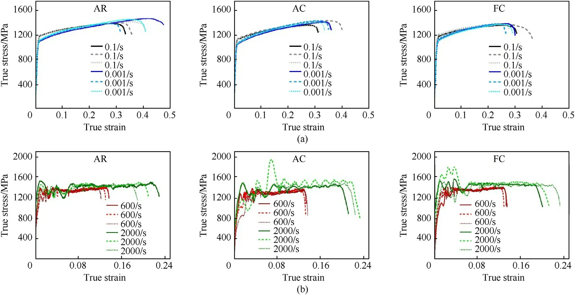
Fig.3.True stress-strain curves of uniaxial compression tests conducted on cylindrical samples (Ø6 mm × 6 mm) of hot-rolled Ti-6Al-4V in the conditions AR,AC and FC.The applied strain rates are shown separately: (a) Quasi-static strain rates;(b) Dynamic strain rates.Note the different scaling of the true strain axis in (a) and (b).
Dynamic loading curves are demonstrated in Fig.3(b).Observed oscillations in the dynamic stress-strain signals are reported to be caused by the neglected dimensions of wave propagation,leading to the so-called Poisson’s effect [13],and by the effects of wave dispersion[44]through the bar configuration during SHPB testing.The occurring oscillations limit the direct interpretation of the comparison between the three material conditions,leading to temporary peak stress levels of >1900 MPa at 2000 s-1in the plastic region,whereas mean plastic stress lies between 1400 and 1500 MPa.However,significant differences are observed between the strain rates of 600 and 2000 s-1.At 600 s-1the applied load did not lead to catastrophic failure of the sample and plastic deformation occurred until a true strain of about 0.14.Mean stress values are situated slightly above 1300 MPa,whereas the AC samples exhibit slightly lower stress levels of about 1300 MPa.Applying 2000 s-1leads to changed tendencies in deformation behaviour.Catastrophic failure due to shear deformation under about 45°to the sample length axis is observed and the strain to failure reached values of up to 0.23.Lowest strain to failure of 0.19 are reached for sample condition AC.Additionally,the amplitudes of oscillations are significantly larger at 2000 s-1for all three microstructure variants.
The temperature dependence is clearly ascertained by the quasistatic tests at 100°C and 200°C and the applied strain rate of 0.001 s-1.Compared to RT tests it is observed that with increased temperature the yield point and the stress level of plastic deformation is shifted to lower values,while the strain to failure becomes increased.It can be outlined,that already at 100°C strength is lowered by about 100 MPa and an additional decrease of about150 MPa is observed when the load gets applied at 200°C.However,maximum strain and stress are accompanied by large standard deviations,as observed for quasi-static tests from Fig.3(a).Stressstrain curves at elevated temperatures are not shown,but data are taken into account for the evaluation of JC parameters,respectively.
To summarize the comparison of the results from compression tests it can be stated that the microstructural influence on mechanical properties of the investigated conditions of Ti-6Al-4V is not exceeding the standard deviation in the discussed flow curves.While,on the one hand,AR samples exhibit largest stress and strain values when tested in the quasi-static regime,on the other hand,they are accompanied by largest standard deviations,as seen in Figs.3(a)and 3(b).Significant differences were found for the yield points,where AR and FC samples reached larger stress values than AC at quasi-static strain rates at RT as well as at elevated temperatures.It is assumed that the AC microstructure exhibits lower strength due to grain coarsening,which occurred during solution heat treatment.
The subsequent characterization was focussed on SHPB samples conducted at 2000 s-1at RT,because no damage-related phenomena were observed in the microstructures of samples tested at the other loading conditions,i.e.at lower strain rates.However,for the purpose of comparison between the three grades AR,AC and FC LOM,images of the microstructures prior to testing are shown(see Figs.4(a)-4(c)).While the AR and FC conditions(Figs.4(a)and 4(c))contain typical rolling microstructures with elongated lamellae,Fig.4(b) illustrates the duplex microstructure of condition AC.Figs.5(a)-5(c) reveals the microstructures of the three tested samples taken by means of LOM.Fig.5(d) shows the IPF map of a selected region around an ASB,contained in Fig.5(a),which was generated via EBSD analysis.It could be demonstrated that in all samples the formation of ASBs was observed as prevalent damage mechanism and that also mechanical twinning occurs in the hexagonal α phase during dynamic loading.The detailed section displayed in Fig.5(d)reveals the nanocrystalline structure of the ASB which is situated along a crack,that might have developed when the local strain within the ASB overcame a certain level,or due to the fast heating and cooling events during the experiment.The grain size within the ASB is assumed to be in the range of 50 nm which goes in line with findings on dynamically loaded Ti-6Al-4V from other authors [15,19,45].Furthermore,in the region next to the ASB colour gradients within single grains are revealed by the IPF map shown in Fig.5(d).These let assume that plastic deformation also took place in the regions next to ASBs,because the local misorientation is increased.Approaches in literature were made to calculate a value representing the defect density,which can be caused by deformation.To this end,often the geometrically necessary dislocation(GND)density is taken into account.By EBSD both the grain curvature [46]and the Kernel Average Misorientation (KAM) [47]can be used for an approximation of the GND density.In both cases the calculation of a discrete value uses the Burgers vector of the respective crystal structure,whereas in the hexagonal α phase,containing a hexagonal crystal lattice,not only one Burgers vector exists [48].However,as shown in the work of Ramazani et al.[47]the KAM value is denoted as a factor of proportionality for calculating the GND density.As a consequence,for hexagonal materials the KAM factor can be taken into account in order to be related to the GND density.The KAM map of the same region as shown in Fig.5(d) can be found in Fig.6(a).For a better illustration of the KAM factor in dependence of the distance to the ASB,Fig.6(b) reveals the KAM factor over the image diagonal,termed diagonal distance,demonstrating the increase of defects with decreasing distance to the ASB.The trend of the KAM factor is emphasized by applying an exponential data fit,which are separated to each side of the ASB.Within the remaining microstructure of the ASB a low KAM factor and globalized grains are observed,which allows to make the assumption that the ASB formation leads to local recrystallization.The observed globularization caused by severe local deformation and following recrystallization have been described by other authors as well [14,19].Also increased microhardness is reported to occur in these ASBs and in adjacent regions[19,49,50].While for Ti base alloys it can be summarized that the hardness in ASBs is not as much increased as it is the case for other materials.However,Winter et al.[49]found that ASBs can reach a hardness of 7 GPa and surrounding zones 3 GPa,whereas the mean hardness of the undeformed microstructure lies at 2 GPa.In the work of Timothy et al.[50]it is discussed that the shear bandwidth has an influence on the resulting hardening effect and that thermal relaxation processes can equal the hardening or even soften the material within the ASB.However,as the resulting effect on the ASB hardness might depend both on temperature and deformation process,the increased KAM factor,i.e.the defect density in the present work lets suggest that strain hardening has occurred in the neighbouring zones of ASB.

Fig.4.Microstructures of the investigated sample conditions of the hot-rolled Ti-6Al-4V plate by means of LOM images:(a)As-rolled(AR);(b)Solution heat treated and air-cooled(AC) exhibiting bimodal/duplex microstructure;(c) Mill-annealed and furnace-cooled (FC).
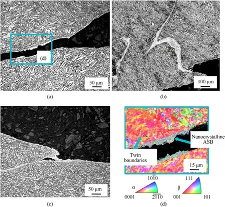
Fig.5.LOM images of hot-rolled Ti-6Al-4V samples tested via SHPB(2000 s-1)in different microstructural conditions:(a)AR;(b)AC;(c)FC;(d)Showing an IPF map of the marked section in (a),generated by EBSD analysis.
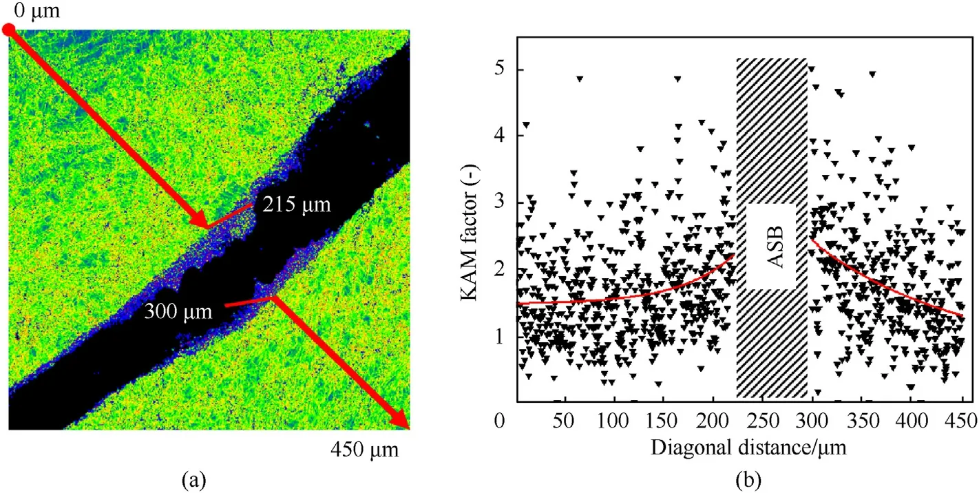
Fig.6.(a) KAM factor map of an ASB and the neighbouring area;(b) KAM factor values over the image diagonal as noted,fit by exponential functions (see text).
3.2.Identification of the parameters of the constitutive model
For the present study,a Johnson-Cook (JC) constitutive model,considering contributions of strain hardening,strain rate sensitivity and thermal softening on the flow stress during plastic deformation is chosen and defined by the equation:
The so-called JC parameters can be defined as follows:Arepresents the yield stress,Bis the hardening modulus,Cis the strain rate coefficient,nis the hardening exponent,and m is a material constant in the exponent of the homologous temperature.Further constituents are the equivalent plastic strain εp,the dimensionless plastic strain rate*=/0,the reference temperatureT0,the melting temperatureTm,and the actual temperature T.In this study,input parameters were generated from data of quasi-static compression tests at different temperatures and dynamic compression tests at strain rates of up to 2000 s-1.From the conducted compression tests,the JC parameters were evaluated in order to gain FE simulation input parameters for the three material conditions AR,AC and FC.The respective JC parameters are summarized in Table 5.The systematic evaluation of the JC parameters allows a quantified comparison of the three samples.According to this fact,the samples AR and FC behave similar,both in yield stress and strain hardening behaviour.The FC sample is assumed to respond to dynamic loading by increased strengthening(parameters C) when compared to AR and AC specimens,which is more relevant when high strain rates are applied [50].For the duplex/bimodal microstructure (AC) the stress increase through strain hardening is prevalent,but temperature and strain rate dependency are observed to be lower than for the other conditions.
3.3.Comparison: ballistic tests and FE simulation
In this section,results of ballistic tests are compared to those of the built FE simulation based on the JC model by means of the above mentionedv50setup.Furthermore,the microstructural characterization of the impact craters will be related to the appearing damage mechanisms observed in SHPB samples (see Fig.5).
In Figs.7(a) and 7(b) a characteristic frame of the event of impact is given,i.e.45 μs after the bullet tip starts penetrating the Ti-6Al-4V plate.In Fig.7(a) the von Mises stress distribution according to the FE simulation is shown in terms of a 4D“heat-map”layout.Fig.7(b) reveals the equal sequence from the real event by means of high-speed imaging.In both illustrations the circular bulging of the CuZn jacket and the severe deformation of the lead primer are visible.In addition,the FE simulation reveals the propagation of the stress-wave around the impact in a circular shape as well.Another effect,which is only visible in the image of the high-speed footage (Fig.7(b)),is the strong light development around the impact.According to the observed flow direction in the video,pulverized material emerges in radial direction and the strong light contrast lets assume that high local temperatures are present.Also,due to the facts that a bulging the CuZn jacket can be observed and that the steel core is not significantly damaged by the impact,it is presumed that the fine bright particles are mainly erosion products occurring from the Ti-6Al-4V plate.
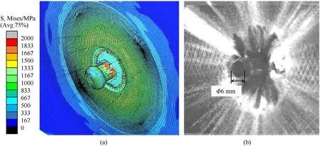
Fig.7.Impact event of a 0.308 Winchester projectile on hot-rolled Ti-6Al-4V plate(AR).Comparison between(a)FE model and(b)high-speed video footage.The frame is taken at t =45 μs after the bullet reached the plate.
In Fig.8 the comparison between FE simulation and reality is continued by the examination of the cross-section of a tested plate.Fig.8(a) shows the radial stress at specific time,i.e.t=15,25 and 40 μs.It is demonstrated that a compression stress front propagates into the plate right next to the plastically penetrating bullet core.According to the FE simulation,compression stress levels locally reach values of up to 4500 MPa,thus exceeding the maximum compression stress measured via SHPB by the factor of 3.On the reverse side of the sample a tension stress field develops,which is reported to be caused by the wave reflection at the free surface[9].The maximum tensile stress of about 1500 MPa is reached shortly before the bullet perforates the plate,close to the back-side of the plate.Tested samples revealed cracks following the shape of the tension stress field,as shown in Fig.8(a).In combination with the hardness mapping,which is also displayed in Fig.8(b),this observation can explain the effect of the impact on the material's hardening and failure comprehensively.While the investigated Ti-6Al-4V alloy cannot withstand the plastic penetration of the projectile at highest local compression stress,the adjacent regions,which are subjected to stress levels below 1500 MPa,undergo a local strain hardening effect,reflected by the increased hardness in this region.On the opposite side of the plate,where high tensile stresses are predicted in the FE simulation,delamination and cracking leads to relaxation of the material and,thus,lower hardness values are measured in the penetrated state.It can be concluded that the pulverized material(Fig.7(b))was mainly emerging from the front side of the plate due to high compressive stress.An enlarged crater is visible in Fig.8(b),arising from the direct contact between bullet core and Ti-6Al-4V plate,where modelled stress also exceeds the maximum stress levels,which were obtained during SHPB experiments.
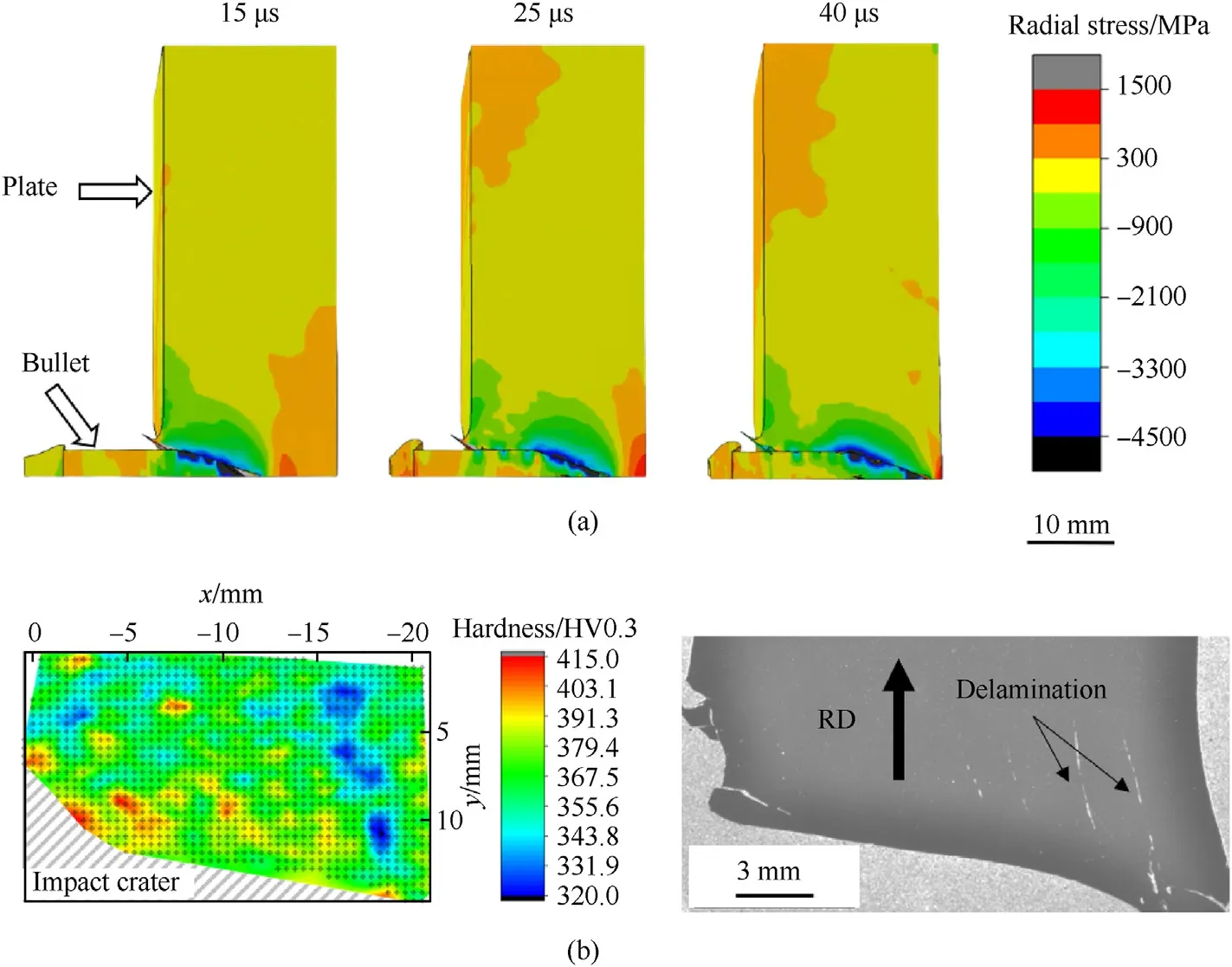
Fig.8.Cross-section of ballistically penetrated Ti-6Al-4V plate.(a)Radial stress at specific time steps 15,25 and 40 μs;(b)Micro-hardness mapping after impact in relation to the polished cross-section after impact (see text for details).
Results of the v50test series,conducted on the three material conditions AR,AC and FC are shown in Figs.9(a)-9(c),respectively.Here,penetration depth is plotted against bullet velocity in order to compare between physically measured values (red) and simulated values (blue).Both exhibit deviations which occur for different reasons.Material inhomogeneities,manufacturing tolerances of bullets and deviations in the test setup,e.g.impact angle,and the tolerances of the applied measurement methods can be considered as possible parameters influencing the experimental results.In case of numerical results,e.g.excessive distortion and hourglass effects,are expected to cause a spread of the simulated values [51,52].Therefore,95% prediction bands are shown in Fig.9 for the generated data.It can be seen,that the trend between penetration depth and bullet velocity is of a linear kind in the investigated regime.Furthermore,for all three conditions,i.e.for AR,AC and FC,the error between bullet-measured values and simulated values increases with increasing bullet velocity close tov50.

Fig.9.Penetration depth versus bullet velocity for the three material conditions AR,AC and FC according to the conducted v50 tests.Measured values (red) and simulated values(blue) are shown separately.
The occurring deformation and damage mechanisms are exemplified in the SEM micrographs shown in Fig.10.For demonstration,characteristic features were selected from the AR microstructural state.However,it has to be mentioned that similar phenomena were observed for AC and FC samples.Fig.10(a) illustrates an ASB with delamination along the ASB.It is frequently observed throughout the whole cross-section that voids or cracks are directly situated inside an ASB,both close to the impact crater or the free surface as well as in the centre of examined cross-sections,as shown in Fig.8(b).Fig.10(b)also shows an ASB,but here a crack follows a “zig-zag” path parallel to the ASB,approximately at a distance of 25 μm from ASB.However,this behaviour has been observed less often in the investigated samples.It can be concluded that in both types of tested samples,i.e.SHPB samples and ballistic plates,adiabatic shearing occurred as the main failure mechanism.Therefore,input data for the JC model are assumed to consider the relevant material behaviour on macroscopic scale.In Fig.10(c) a region of two twinning modes is captured.The image reveals that regions of parallel aligned lamellae,i.e.also exhibiting the same crystallographic orientation,tend to twinning as a deformation mechanism.These regions,so-called “microtextured regions”(MTRs)can develop during the deformation process of a Ti-6Al-4V ingot exhibiting an as-cast,i.e.lamellar starting microstructure showing large grains,which act as microstructural inhomogeneities[53,54].Fig.10(d)shows an IPF map of an area near the impact crater containing an“ASB loop”.It has to be mentioned that such complex geometries of ASB planes,forming 3D networklike structures,were obtained in penetrated sample.Also the visible ASB width may significantly depend on the angle between the prepared surface plane and the lateral ASB plane.As a consequence,we like to emphasize that for ballistically tested samples the frequently conducted quantitative examination of ASBs [7,15,55],e.g.ASB width,grain structure,correlation to microstructure etc.,requires a careful evaluation,due to their highly complex appearance.However,the“ASB loop”from Fig.10(d)was a unique finding in the present investigation.The features of the ASBs are similar to those appearing in SHPB tested samples(see Fig.5(d)),i.e.globular,nanocrystalline and randomized in texture.
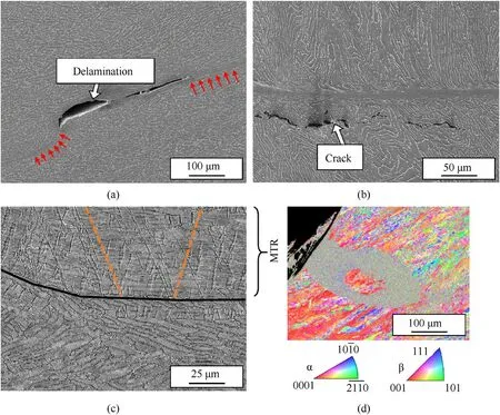
Fig.10.SEM micrographs of a penetrated Ti6Al-4Vplate(AR)in cross-sectional view:(a)Delamination(arrow)within an ASB;(b)Crack in adjacent region of an ASB;(c)Mechanical twins in MTR (dashed lines indicate twin orientation;(d) “ASB loop” emerging directly from the impact crater.
Fig.11 contains results from microstructural characterization of the Ti-6Al-4V AR plate,but here the focus is lying on the characterization of an occurring IMP.The IMP was found by means of LOM as well as SEM using backscattered electrons (BSE) contrast.Its chemical composition was analysed via EDS.While an overview image is given in Fig.11(a),containing an ASB network and multiple locations of detected IMP,Fig.11(b)shows a more detailed view of both the IMP as a continuous layer along the impact crater and an IMP in the bulk of a crater-near ASB.Fig.11(c) contains a detailed image of the IMP layer and shows the summarized EDS analysis conducted on three selected positions within IMP,marked by yellow crosses.The chemical composition of the IMP was almost identical,independent on the exact measurement position.Results from Fig.11(c) reveal that the IMP consists mainly of Ti,Fe,Al and minor fractions of V and Cr,and is generated during the impact process.It is expected that the continuous layer of 5 μm thickness was formed due to direct contact between bullet core and Ti-6Al-4V plate and that crack channels are filled with the liquid phase when high pressure and temperature occur locally over a limited time span.Also large deformation paths can lead to local overlapping and bulging of the material,so that IMPs can be found at more than 100 μm distance from surface(see Fig.11(a)),without a visible connection to the continuous layer.These IMP were detected in all three sample types AR,FC and AC in the same way of appearance.Unfortunately,no investigations by means of transmission electron microscopy (TEM) could be conducted in the framework of this study.Thus,a full characterization and classification of the appearing IMP were not possible.According to the binary phase diagram TiFe discussed in Ref.[56]it is suspected that the phase is of type TiFe (ordered B2 structure) with additional Al substituting Fe in the lattice.

Fig.11.SEM based characterization of an IMP found along the impact crater surface and in the adjacent region.(a)Overview image of occurring ASB networks and IMPs;(b)detailed view of the IMP crater layer;(c)EDS analysis of IMP,and(*c)spot measurement for EDS analysis on an IMP crater layer.Yellow cross symbols are highlighting the spots which were taken into account.
As the last direct comparison between experimental and modelled results of the ballistic tests,thev50curves of the three material conditions AR,AC and FC are shown in Fig.12.The experiments lead to almost equalv50of the tested samples.Here,the evaluated velocities vary from 880 to 881 m/s,with a minimum standard deviation of 6.7 m/s for the FC material.The standard deviation of the AR plate is determined as the largest with 22.4 m/s,whereas the AC plate exhibits 18.5 m/s.Due to the more significant difference between the standard deviation of the three materials this value can be taken into account for a quality criterion of the material's ballistic performance.At lower velocities a small perforation probability can be expected when the standard deviation is low,even though the materials exhibit equalv50values.In the present case,for example,the AR plate has a 0.001% perforation probability at 797 m/s,while the FC plate exhibits the same probability when hit with 856 m/s bullet velocity.However,standard deviation might mainly depend on microstructural inhomogeneities,e.g.the presence of MTRs,which were not taken into account during FE modelling.
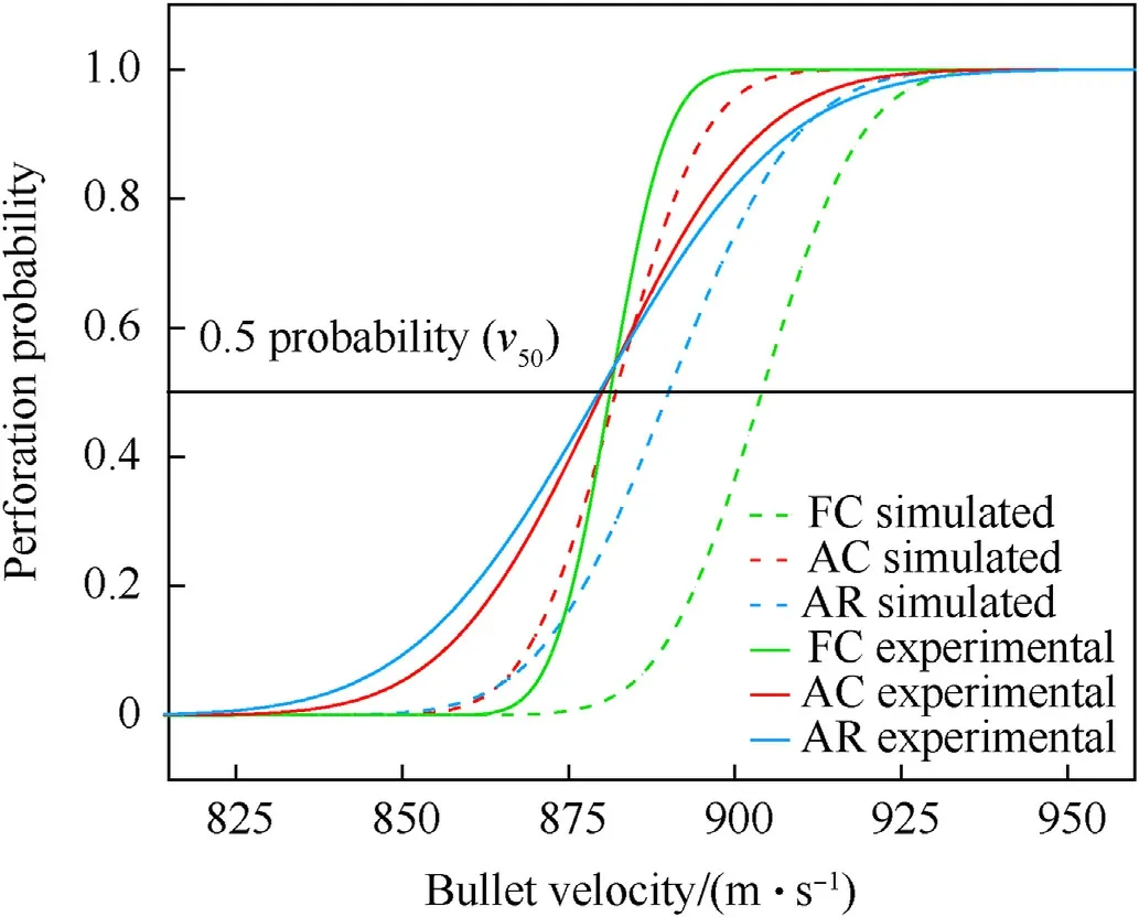
Fig.12. v50 ballistic curves of hot-rolled Ti6Al-4Vplates in the conditions AR(blue),AC(red) and FC (green).The diagram contains experimental ballistic values (solid line)and simulated values (dashed line).
In general,it can be stated that the simulation overestimates the material's ballistic performance,represented by thev50value,by up to 20 m/s for the FC condition and by about 3 m/s for the AR condition.The overestimation of the ballistic performance is expected to originate mainly from thermal effects.At first,conducted SHPB experiments considered temperatures from RT to 200°C for the evaluation of the JC parameter m.Due to the finding of an IMP and supported by the work of Ref.[14,15,19],the occurring peak temperature in the conducted ballistic experiment is assumed to exceedTβ,which lies at about 1000°C for the applied alloy [57].Because of missing data,the thermal softening behaviour for this temperature range could not be considered in detail.However,when compared to the corresponding work of [58-60]the determined parameter m is located at typical levels.It is expected that a comparable temperature increase occurs in ASBs within the SHPB samples as well[17,61].Thus by fitting high strain rate deformation data this behaviour is already taken into account.At second,the formation of an IMP due to a eutectic reaction between the main elements in plate and bullet core,i.e.Ti and Fe,was not considered in the applied FE model.Moreover,the resulting effect of the formation of a molten phase that is present in the event of the ballistic impact has not been described for this material combination so far.However,according to the obtained results it is presumed to additionally soften the material in practical experiments,which might lead to an overestimation of thev50value.
A possible explanation for the lower standard deviation within ballistic tests and the improved dynamic properties of the FC condition can be given with regards to the applied heat treatment.The low cooling rate due to furnace cooling results in increased time for diffusion during phase transformations.In the cooling segment,the chemical elements tend to diffuse towards that phase in which they are favourably accommodated,i.e.Al and O are enriched in the α phase and V and Fe are enriched in the β phase,when compared to the air-cooled samples.Considering that higher content of Al and O decrease the tendency of deformation via mechanical twinning,an influence on the deformation behaviour is legitimate.As microstructural characterization shows,mechanical twinning as a deformation mode is strongly localized in MTRs and therefore is suspected to enhance the activation of adiabatic shearing.This means,that reduced twinning of the FC samples might lead to improved dynamic properties in this particular case.Furthermore,it can be concluded that the lower cooling rate results in more time for diffusion at elevated temperatures and can lead to a globularization effect,which were especially observed for the β phase,compare Figs.4(a) and 4(c).This leads to a certain homogenizing effect regarding the microstructure.
3.4.Impact temperature
Considering the eutectic transformation between Ti and Fe,e.g.as shown in the binary phase diagram[56],the lowest temperature where a liquid phase is stable lies at 1085°C on the eutectic line between the phases FeTi and β-Ti.An experimental approach for approximating the melting temperature between the material pairing:Ti-6Al-4V plate and the 100Cr6 bullet core,was conducted by the described dilatometer experiment (see section 2.2).After heating up Ti-6Al-4V and 100Cr6 steel in direct contact to each other at a continuous heating rate of 0.5 C°/s the event of melting due to diffusion across the contact zone was reached at 1188°C.An additional chemical analysis via EDS showed that a similar IMP as seen in Fig.11 was formed in the contact zone during this experiment.Taking into account the necessary time for diffusion,it is probable that the onset of melting is shifted to higher temperatures than the eutectic point.An approximation of the diffusion path of Fe in Ti can be conducted using the equation,wherexis the mean diffusion path of a single atom.By applying the diffusion constant D for Fe in pure β-Ti at 1000°C from Ref.[62]and by considering the time intervalt=276 s,in which temperature was higher than at leastTβ,the mean diffusion path can be approximated to=16 μm,which demonstrates that the formation of a diffusion zone can lead to a eutectic transformation by changing the local chemical composition in a significantly large zone.In addition,Al,Cr and V will influence the process as well as might alter the eutectic temperature.As a consequence,it is assumed that the local,severe deformation,mainly occurring in ASBs,leads to a respective increase of temperature to values >Tβ.
In order to validate the assumption that the investigated IMP has formed in a liquid state,the thermomechanical evaluation of the FE model was taken into account as well.By qualitatively estimating the temperatures which occur during impact,the FE simulation helps to confirm the described hypothesis of the formation of low-melting eutectics.The authors decided to limit temperature evaluation via the FE model to the FC condition,where the largest error between experimental and modelledv50value occurred.In Fig.13,the cross-section of the impact area at the front side of the plate is shown.By a comparison between the simulated temperature profile and the observed microstructure,the damage mechanisms and the formation of the IMP are further legitimated.In addition,the modelled occurring stresses and the shown highspeed video frame (see Fig.7) can be taken into account for describing the observed mechanisms.It can be seen that locally temperatures above the eutectic temperature are predicted with a local maximum of 1320°C at the shown penetration depth.The comprising results are tempting to speculate that in regions where maximum compression stress was observed and where modelled temperature exceeds the eutectic point,chipping by adiabatic shearing and local melting effects are responsible for an extended crater on the front side,before the projectile plastically continues its penetration path.A more detailed view on the modelled temperature is given in Fig.14,where temperature is plotted over impact velocity and penetration depth.Layers 1-15,as shown in Fig.14(a),are defined in order to demonstrate the dependence of the distance from impact centre on temperature.The layer number equals the distance from centre d-1 in unit of mm,i.e.layer 1 is at the centre.Selected layers are shown in Fig.14(b),where a 3D plot combines the data.Fig.14(b) shows node temperatures at lower penetration depths above the liquid’s temperature,thus implicating melting of the plate material due to higher energy absorption.It is,for example,discussed in Ref.[19]that melting and solidification in the ASB enhance brittle fracture locally.Especially when solidified material,in the present case an IMP,is deformed,so-called “zig-zag”-cracks,such as seen in Fig.10(b),are known to occur.Furthermore,a temperature increase of the penetrated nodes and layers can be observed,which decreases with the number of nodes and layers or,in other words,with the distance from the penetration centre.Subsequently,the data of the respective nodes(see Fig.14(a)) were extracted,processed and visualized (see Fig.14(b)).
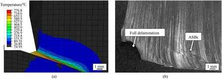
Fig.13.Comparison of (a) the simulated temperature during the event of impact and (b) the microstructural deformation and damage mechanisms visualized by a LOM image,taken next to the impact crater.

Fig.14.(a)Nodes and corresponding layers for data extraction before projectile penetration with the simulated penetration depth ssim and(b)visualization of respective node and layer temperatures after penetration to a certain depth.
4.Conclusions
In the present work ballistic tests and compression tests as well as different strain rate and temperature were conducted on hotrolled Ti-6Al-4V exhibiting different microstructures (AR,AC and FC).Experimental data determined in order to formulate a FE model to simulate the ballistic impact behaviour for three material conditions.Supported by detailed microstructural characterization a comparison could be made.The following conclusions can be drawn:
· In the course of compression tests only minor microstructural influence was obtained.However,the evaluation of the JC parameters let assume that the material with bimodal microstructure (AC) exhibits a different hardening behaviour.Yield point and strength level were found to be lower for this duplex microstructure with increased grain size,when compared to the as-rolled (AR) and the mill-annealed (FC) microstructures.
· The best ballistic performance in the conductedv50tests,using 0.308 Winchester projectile was achieved by the FC sample.While the ballistic limit velocityv50did not vary significantly between the three microstructural conditions,the standard deviation of perforation probability was the lowest for the FC condition,i.e.a higher ballistic security at lower bullet velocity is given.
· The FE simulation remodelled the ballistic impact by means of av50evaluation to a maximum error of <3% (FC condition).However,for all three investigated variants the model has overestimated the ballistic limit velocityv50,which might be caused by neglecting specific damage mechanisms during the deformation of microstructure.The comparison of experimental and simulated penetration depth showed that the obtained errors result from calculations at higher bullet velocities,while below about 850 m/s the values match more accurately.
· Microstructural characterization of dynamically tested sample gave insight into occurring damage mechanisms.While mechanical twinning and the formation of ASBs were observed in both dynamically compressed and perforated samples fromv50tests,the formation of an IMP was only observed in microstructure of the latter.It is assumed that texture-related material inhomogeneities and the eutectic reaction between Ti and Fe,which were not considered in the evaluation of the JC parameters,further decrease the ballistic limit velocity.
· By means of microstructural characterization in terms of a dilatometric melt experiment,and,also in accordance with simulation data,the peak temperatures in the region of severe deformation exceed the eutectic temperature of binary TiFe,which is suspected to lie at 1098°C.The estimation of a maximum temperatures of 1961°C under high pressure are suspected to lead to the eutectic reaction between the main elements Ti and Fe,which leads to the formation of an IMP in the developed impact crater.
Declaration of competing interest
The authors declare that they have no known competing financial interests or personal relationships that could have appeared to influence the work reported in this paper.
杂志排行
Defence Technology的其它文章
- Numerical simulation of flow field characteristics and theimprovement of pressure oscillation of rotating detonation engine
- The dynamic response of a high-density polyethylene slow-release structure under launching overload
- Adaptive saturated tracking control for solid launch vehicles in ascending based on differential inclusion stabilization
- Comparative investigations of ternary thermite Al/Fe2O3/CuO and Al/Fe2O3/Bi2O3 from pyrolytic,kinetics and combustion behaviors
- Impact point prediction guidance of ballistic missile in high maneuver penetration condition
- Deep learning-based method for detecting anomalies in electromagnetic environment situation
