Numerical study of wheel-rail adhesion performance of new-concept high-speed trains with aerodynamic wings
2023-08-22YangCHENLinJINGTianLILiangLINGKaiyunWANG
Yang CHEN,Lin JING,Tian LI,Liang LING,Kaiyun WANG
State Key Laboratory of Traction Power,Southwest Jiaotong University,Chengdu 610011,China
Abstract: Wheel-rail adhesion is a complex tribological problem of wheel-rail rolling contact and is closely related to the operational safety of high-speed trains.A new design concept of high-speed trains was recently proposed with an expectation of a reduction of equivalent weight and total energy consumption by installing aerodynamic wings (aero-wings) on the roof,but it was accompanied by the disadvantage of deteriorating wheel-rail adhesion performance.In this study,a comprehensive multibody dynamics (MBD) model of the high-speed train with predesigned aero-wings is established using the commercial software SIMPACK,in which the real aerodynamic characteristics of the train are taken into account.The available adhesion and adhesion margin are employed to evaluate the wheel-rail adhesion performance.The influences of aero-wing lift,train speed,and contact conditions on the wheel-rail adhesion level are discussed.The results show that the load transfer caused by the action of aerodynamic load and braking torque was the main reason for the inconsistent adhesion condition of four wheelsets.The influences of aero-wing lift and train speed on the wheel-rail adhesion performance are coupled; the available adhesion of both motor car and trailer is negatively correlated with aero-wing lift and train speed under all contact conditions,while the variation law of adhesion margin with train speed shows differences under different contact conditions.When the wheel-rail interface was polluted by a ‘third-body medium’ such as water and oil,the wheel-rail adhesion performance was dramatically reduced and the wheelset tended to reach adhesion saturation and slide.However,track irregularity had little effect on the adhesion performance and could be ignored to save calculation time.These results are of positive significance for reducing the wheel idling or sliding phenomenon and to ensure the safe operation of high-speed trains with aero-wings.
Key words: High-speed train; Wheel-rail adhesion; Aerodynamic wing; Multi-body dynamics (MBD)
1 Introduction
Speed is an eternal theme of transportation development.The continuous increase of train operation speed represents the maturity and progress of highspeed railway technology,facilitating business exchange and promoting regional economic and social development (Jing et al.,2021,2022a,2022b; Zhou et al.,2023).However,the increase of train operational speed brings many problems,such as the increase of train aerodynamic resistance and energy consumption,aggravation of wheel wear,and shortening of wheel service life (Jing et al.,2023).In order to take into account both economic and ecological benefits while increasing train speed,a new design concept of high-speed trains installing aero-wings on the roof was developed on the basis of not changing the current pattern of highspeed railways,but expecting to achieve weight reduction,energy conservation,and consumption reduction of high-speed trains by increasing their aerodynamic lift.
The normal traction/braking performance of highspeed trains depends on good adhesion conditions,but the aero-wing lift will not only weaken the wheel-rail interaction,but also worsen the wheel-rail adhesion performance.This poor adhesion performance means that the available adhesion is too low to meet the traction or braking demand,which will lead to train delay,longer braking distances,and wheel idling and sliding which can easily cause wheel flat,rail scratch,and other wheel-rail contact surface damage (Olofsson,2009; Arias-Cuevas,2010).Therefore,clarifying the influence mechanism of aerodynamic lift on wheel-rail adhesion performance is of great significance to reduce such wheel idling and sliding and to ensure the safety of high-speed trains with aero-wings.
Wheel-rail adhesion is a complex tribological problem in wheel-rail rolling contact mechanics.An accurate and efficient description of wheel-rail adhesion characteristics is important to further study the wheelrail interaction and adhesion performance in complex operation conditions.Therefore,many scholars have carried out experimental research to directly obtain realistic wheel-rail adhesion characteristics.Ohyama(1991),Zhang et al.(2002),Chen et al.(2008),Arias-Cuevas et al.(2010),Wang et al.(2011),and Chang et al.(2019) investigated the adhesion behavior using a rolling contact facility; they summarized the influence laws of wheel-rail contact surface contamination,train speed,axle load,temperature,contact surface roughness,and other factors on wheel-rail adhesion characteristics; most of the above factors have significant effects on wheel-rail adhesion.
The uncertainty and strong nonlinearity of wheelrail adhesion make it very difficult to establish a relevant theory and numerical model that can fully describe the change of wheel-rail adhesion coefficient with slip.Classical wheel-rail rolling contact theories developed in the early stages,including Carter’s 2D rolling contact theory (Carter,1926),the Vermeulen-Johnson theory(Vermeulen and Johnson,1964),Kalker’s original theories (Kalker,1967,1982,1991),and the Shen-Hedrick-Elkins theory (Shen et al.,1983),are all based on the assumptions of wheel-rail contact elastic deformation and the traditional Coulomb friction law.However,there are two important discrepancies between the measured creep force versus creep curves and the theoretically predicted curves (Vollebregt,2014): (i) the initial slope of the measured creep curve is lower than the predicted one,and (ii) the measured creep force decreases with the increase of creepage after attaining a maximum,which cannot be represented by the theoretical models.These two discrepancies are usually attributed to the solid and fluid layers between the wheel-rail contact interface,surface roughness,temperature,and other factors.Therefore,in the subsequent development of the wheel-rail rolling contact model,scholars introduced the influence of these factors on the wheel-rail tribological behavior.Wu et al.(2014) established a 2D numerical model of wheel-rail rolling contact to study the wheel-rail adhesion characteristics considering the effects of surface roughness and mixed oil and water contamination.Chen et al.(2005) estimated the wheel-rail adhesion coefficient using a 3D contact numerical model in combination with elastohydrodynamic lubrication theory; their results indicated that the direction of surface roughness had an important impact on the adhesion coefficient.Tomberger et al.(2011) proposed a wheel-rail contact model combined with an interfacial fluid model,which could compute the local mechanical and thermal stress distributions in the contact area and the resulting traction-creep curves under the coupling action of interfacial fluid,surface roughness,and contact temperatures.However,among the many wheel-rail rolling contact models (including the above models) only a few are readily available for use in vehicle dynamic simulation.The most commonly used are Fastsim (Kalker,1982),modified Fastsim (Spiryagin et al.,2013),and Polach’s method (Polach,1999,2005),which have certain differences in the accuracy,speed,and generality of the creep force calculation.Compared with Kalker’s complete theory CONTACT (Kalker,1991),Fastsim has acceptable accuracy and a much shorter calculation time.Modified Fastsim introduces variable contact flexibility replacing the constant Kalker’s reduction factor to achieve a good agreement with typical measurements.Polach’s algorithm is a rapid method and is suitable for characterizing the creep force near saturation.However,Polach’s algorithm is less accurate in the presence of large spin,so Polach’s method is more suitable for vehicle dynamic simulation of traction/braking than for curving operations (Vollebregt et al.,2021).
The development of a wheel-rail contact model integrated in the vehicle dynamic simulation has promoted research on evaluating the wheel-rail dynamic interactions under complex operation conditions.Yang et al.(2022) established a 3D heavy-haul train-track coupled dynamic model into which a low adhesion zone(LAZ) and an anti-slip control algorithm were embedded to analyze the wheel-rail dynamic interaction induced by wheel polygonal wear under normal and low adhesion conditions.Xiao et al.(2022) adjusted the fitting parameters in modified Fastsim according to the measured adhesion data and investigated the dynamic behaviors of high-speed trains under wet and low-adhesion conditions.Wu et al.(2022) proposed a simplified numerical method to extend Kalker’s simplified theory (Fastsim) to modeling the measured adhesion characteristics,and the variation laws of creep force,creepage,and the potential wheel-rail damage in the LAZ were studied.
Because the new concept of high-speed train with aero-wings was put forward recently,little relevant research on the aerodynamic characteristics of aerowings installed on high-speed trains has been carried out based on computational fluid dynamics simulation.Wang et al.(2022) investigated the influence of roof-to-wing distance and angle of attack on aerodynamic characteristics of airfoils and carried out an optimization design of airfoils.Gao et al.(2023) discussed the effects of the connection rod between the wing and the train roof,incoming flow velocity,wingroof height,and angle of attack on aerodynamic characteristics of wings.Yan et al.(2022) analyzed the influence of the wall effect and wing-wing interactions on the aerodynamic characteristic of tandem wings and surveyed the aerodynamic lifts and resistances under different tandem wing layouts.However,there is no relevant research on the influence of aero-wing lift on wheel-rail interaction and wheel-rail adhesion performance,which is necessary for ensuring the operational safety of a high-speed train with aero-wings and needs to be investigated.In this study,a comprehensive multibody dynamics (MBD) model of the high-speed train with aero-wings was established using the commercial software SIMPACK,where the nonlinear characteristics of wheel-rail contact were considered and the corresponding aerodynamic load induced by aero-wings was taken as a boundary condition in the model.Subsequently,the wheel-rail available adhesion and adhesion margin were introduced as the evaluation indicators of the wheel-rail adhesion performance.Finally,the simulation results of wheel-rail contact forces were further processed,and the influence mechanisms of aerowing lift,train speed,wheel-rail contact conditions,and track irregularity on wheel-rail adhesion performance were discussed.
2 MBD model of high-speed train with aero-wings
To explore the influence mechanism of aero-wing lift on wheel-rail adhesion,a comprehensive MBD model of the high-speed train with aero-wings was established using commercial software SIMPACK.Details of the dynamic model will be mainly introduced from the following aspects: the high-speed train model,the wheel-rail contact model,and the aerodynamic and braking characteristics of the train.
2.1 High-speed train model
A dynamic model of a typical high-speed train of eight vehicles with aero-wings was developed,as shown in Fig.1.The overview of the eight-marshalled train from the side view and front view is shown in Figs.1a and 1b,respectively.Fig.1c focuses on the first three cars and the center of gravity of the car body; the installation positions of the wings have been marked in.The aero-wings have the same longitudinal layout on No.3 to No.6 vehicles.The longitudinal layout of aero-wings on No.7 and No.8 vehicles is the same as on No.2 and No.1 vehicles.The head and tail cars are trailers and the middle cars are all motor cars.The installation position of the air conditioning deflector is reserved on No.2 and No.7 vehicles.Each vehicle is mainly composed of a car body,two bogies,four wheelsets,eight axle box rotary arms,and several wings.The vehicle body is supported by the bogie frame through the secondary suspension,and the wheelset is connected with the bogie through the primary suspension.Except that the axle box rotary arm only has the pitch degree of freedom (DOF),and the wing is fixedly connected with the car body,other components of the vehicle system include six DOFs,and the model has a total of 472 DOFs.In addition,the following considerations were taken into account when establishing the dynamic model: (1) all components of the model were assumed as rigid bodies; (2) the nonlinear characteristics of couplers and suspension system components including bump stops,lateral/vertical dampers,and yaw dampers were considered; (3) only the mass and DOFs of the motor were considered and the gear transmission was excluded in the motor vehicle model,so the braking torque was directly applied to the wheelset.
2.2 Wheel-rail contact model
The wheel-rail contact model is of crucial importance for connecting the train subsystem with the track subsystem and transferring the interaction forces in the dynamic simulations.The key points of wheel-rail contact are the solution of wheel-rail contact geometry and the calculation of normal and tangential forces between the wheel and rail (Yang et al.,2021).
The wheel-rail geometry calculation and online evaluation were realized by force element rail-wheel interface in the contact search algorithm in SIMPACK;results of the contact search were the number of contact patches and their locations which served as the basis for the subsequent contact force solution.The wheel and rail profiles in the model were S1002CN and CN60,respectively.
In the MBD simulation,the normal force of wheelrail contact was solved based on nonlinear Hertzian elastic contact theory and the tangential force was calculated by the Polach model (Polach,2005) whose basic idea is to integrate the shear stress on the contact patch to obtain the magnitude of the composite creep force.According to this model,the variable wheelrail friction coefficient with increasing slip and different reduction factors in the area of adhesion and slip were considered,which are suitable for the drive dynamic simulation of large longitudinal creep and creep force.The wheel-rail creep force is determined as
whereQis the wheel-rail vertical force;kAandkSare the reduction factors in the area of adhesion and slip,respectively.εrepresents the gradient of the tangential stress in the area of adhesion which can be described as
whereCis a proportionality coefficient which characterizes the tangential contact stiffness;aandbare the semi-axis lengths of the contact ellipse;srepresents the total creepage.μdis the dynamic friction coefficient,which can be determined by
whereμsis the static friction coefficient;vsrepresents the total slip velocity between the wheel and rail;Ais the ratio of the dynamic friction coefficient at infinity slip velocity to the static friction coefficient;Bis the exponential reduction coefficient.The parameters used to simulate different wheel-rail contact conditions are listed in Table 1.The adhesion coefficient and the corresponding variable friction coefficient with respect to creepage obtained by the Polach model are shown in Fig.2.It indicates that the friction coefficient decreases monotonically with the increase of creepage,while the wheel-rail adhesion coefficient has a marked maximum value and the level of wheel-rail adhesion coefficient under dry contact condition is significantly higher than that under wet and greasy contact conditions.

Table 1 Parameters for dry,wet,and greasy contact conditions (Polach,2005; Yang et al.,2021)
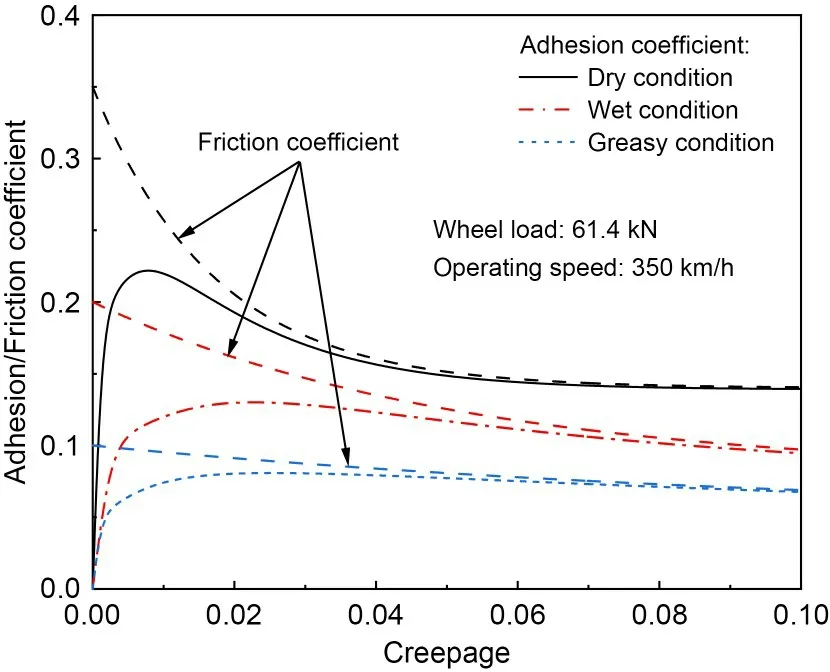
Fig.2 Wheel-rail adhesion characteristic under different contact conditions
2.3 Train aerodynamic and braking characteristics
Compared with the aerodynamic characteristics of traditional high-speed trains running in the open air,the aero-wings installed on the roof could not only produce additional aerodynamic lift and resistance,but also significantly change the flow field distribution and aerodynamic characteristics on the body surface,further affecting the dynamic performance of the train and the wheel-rail interaction.Based on existing research on the aerodynamic characteristics of high-speed trains with and without aero-wings,the results of aerodynamic load obtained from computational fluid dynamics simulation were loaded into the vehicle dynamics simulation.The following considerations were made:(1) Only the aerodynamic lift force of the wing was considered,and the influence of the proportion of lift to car body weight on wheel-rail adhesion was investigated; lift was applied at the installation position of wings on the roof.(2) The aerodynamic load on the car body included the rolling moment,pitching moment,yawing moment,and lift,and the simplified center of aerodynamic load coincided with the center of gravity of the car body.(3) The train resistance including mechanical resistance,momentum resistance,and aerodynamic resistance,was described by the following empirical formula (CEN,2013):
whereω0is the train running resistance (N/kN),andvis the train speed.(4) The aerodynamic characteristic of new high-speed trains with wings was applied to the simulation cases where the aero-wing lift was considered,while that of traditional high-speed trains was applied to the cases where the aero-wing lift is 0.
For brevity,we defined the following dimensionless aerodynamic force coefficient and moment coefficient:
whereFis the aerodynamic force,Mis the aerodynamic moment,andρis the density of air (1.225 kg/m3).The reference areaSrefers to the cross-section area of the high-speed train,which equals 10 m2,and the reference heightHrefers to the height of the simplified center of aerodynamic load,which equals 1.884 m.Tables 2 and 3 show the specific values of the aerodynamic characteristics of trains expressed by dimensionless coefficients,and the assumption was made that these coefficients remain constant at different train speeds.It should be noted that the positive and negative values of these coefficients are based on the global reference coordinate system in the dynamic model.
Considering the train under emergency braking,exerting its maximum braking capacity,the braking curve in the simulation is shown in Fig.3.For the trailer,only the air braking system provides the graded constant braking force and takes 300 km/h as the switching point of high and low braking forces.For the motor car,when the train speed is higher than 220 km/h,electric braking starts to provide part of the emergency braking force which decreases with the increasing speed.The braking force was converted into braking torque and applied to the wheelset directly.
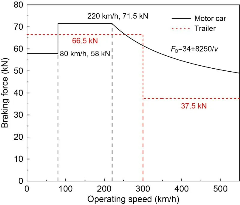
Fig.3 Braking force (FB) curve used in the simulations
3 Evaluation method of wheel-rail adhesion performance
The wheel-rail adhesion-slip phenomenon is essentially a kind of elastic contact interaction (Fang et al.,2018),as shown in Fig.4.Under the effect of axle loadP,elastic deformation occurs in the contact between wheel and rail,forming an elliptical contact patch consisting of adhesion zone and slip zone.When a traction/braking torqueMis applied to rolling wheels,there will be a relative slip velocityvsbetween the wheel and rail in the longitudinal direction,which can be defined as the difference between the translational velocity and circumferential velocity of the wheel and is formulated as
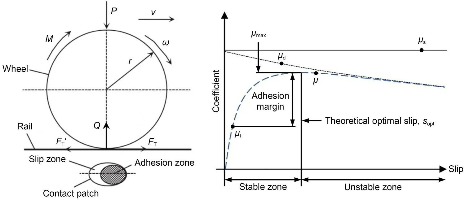
Fig.4 Adhesion-slip phenomenon and adhesion-slip characteristic curve (Spiryagin et al.,2022)
wherevwis the translational velocity of the wheel,ωis the angular velocity of the wheel,andris the rolling radius of the wheel.Then,the wheel-rail longitudinal creepagesxis expressed as (Iwnicki et al.,2020)
Due to the relative slip between the wheel and rail,the tangential interaction forcesFTandFT' are generated in opposite directions on the wheel-rail contact surface.In general,the traction coefficientμtis defined as the ratio ofFTto the wheel-rail vertical forceQ,representing the utilized adhesion under traction control (the same for braking conditions).Although the adhesion coefficientμcan also be defined as the ratio of wheel-rail tangential force to wheel-rail vertical force,it also represents the level of available adhesion which limits the maximum tangential force that can be transmitted between wheel and rail (Spiryagin et al.,2022).When the traction/braking torque applied to the wheelset is lower than the available adhesion level,the wheel-rail operates in the stable zone with a certain margin between the maximum adhesion coefficientμmaxandμt.On the other hand,when the traction/braking torque applied to the wheelset is higher than the available adhesion,the wheel-rail operates in the unstable zone,the relative slip increases rapidly,and the wheelset is in risk of idling or sliding.The static friction coefficientμsand dynamic friction coefficientμdhave an important influence on the wheel-rail adhesionslip characteristic.
The wheel-rail adhesion is of great significance in the normal traction/braking behavior of high-speed trains.Therefore,we chose the available adhesion and adhesion margin as two important indicators to evaluate the adhesion performance of trains,and the indicators were presented in the form of force (Liu et al.,2016),as shown in the following formulas:
whereFμis the utilized adhesion force (i.e.,the wheelrail creep force which is expressed as a function of the creepage/slipsin Section 2.2);Fμmaxrepresents the available adhesion force which can be described as the maximum value of functionFμor the product of maximum adhesion coefficientμmaxand wheel-rail vertical forceQ;Frefis the reference value of the traction/braking force;Fmrepresents the adhesion margin.WhenFmis greater than 0 or less than 0,it reflects the potential available adhesion or the insufficient adhesion between wheel and rail and corresponds to normal operation (s≤sopt) or idling (s>sopt),respectively.Therefore,higher available adhesion and adhesion margin can reduce the risk of wheel idling or sliding and ensure safe and reliable traction/braking of high-speed trains.
Based on the Polach model described in Section 2,when the wheel-rail vertical force,train speed,wheelrail contact conditions,and other relevant parameters are determined,the adhesion-slip characteristic curve can be obtained,and the maximum available adhesion under this state can be calculated.Assumptions made in this paper were that the wheelset always runs along the centerline of the track with little lateral displacement and that the wheel-rail contact position is almost invariant,so the shape of the contact patch and Kalker creep coefficient could be assumed to be constant.Thus,the relationship between wheel-rail available adhesion and train speed and wheel-rail vertical force under different contact conditions can be obtained,as shown in Fig.5.It can be concluded that the available adhesion under dry wheel-rail contact conditions is distinctly higher than that under wet and greasy contact conditions.The available adhesion reduces with the rise of train speed and decrease of the wheel-rail vertical force.
4 Results and discussion
4.1 Descriptions of simulation cases
Based on the dynamic model and the evaluation indicator of wheel-rail adhesion performance,the effects of aero-wing lift,train speed,and wheel-rail contact conditions on the wheel-rail adhesion performance were investigated.According to the expected equivalent weight reduction and the design operating speed of high-speed train with aero-wings,the simulation cases of six lift conditions (the lifts of aero-wings are 0%,5%,10%,15%,20%,and 25% of the car body weight,respectively) with five speed levels (350,400,450,500,and 550 km/h) under three contact conditions(dry,wet,and greasy) were considered.In the simulation,the train runs along an ideal straight track without consideration of track irregularity.This assumption is based on the results in Section 4.6 that track irregularity has no essential influence on wheel-rail adhesion performance and neglecting it enables a shorter calculation time.The aerodynamic load and braking torque are linearly loaded to the target value in 0-2 s and 6-8 s,respectively,to avoid adverse results caused by sudden load changes.It should be noted that it is necessary to keep the train speed constant to calculate the wheel-rail adhesion performance at the specific speed level.By establishing a rigid body (virtual train)whose motion relationship is defined as running at a constant speed along the track (No.9 Joint in SIMPACK,zero DOF),connecting it with the head car with a coupler,and using coupler resistance to balance the braking force,the train can operate at a constant speed under braking conditions.The adhesion performances of the No.4 vehicle (middle car) as a typical motor car and the No.8 vehicle (tail car) as a typical trailer are discussed.Note that only the simulation results of right-side wheel-rail contact are exhibited in this paper due to the similarity of the left-side and right-side wheelrail contact results.
4.2 Influence of aero-wing lift on wheel-rail adhesion
The aerodynamic lift as an external excitation directly affects the wheel-rail contact force which is a key factor in adhesion performance.Fig.6 shows the dynamic wheel-rail vertical forces of four wheelsets of No.4 and No.8 vehicles under dry contact condition when the lift is 0% and 25% of the car body weight,respectively.It can be found that the application of aerodynamic load had an immediate influence on the wheel-rail contact forces.The summation of the wheelrail vertical forces of the 1st wheelset and 2nd wheelset is higher than that of the 3rd wheelset and 4th wheelset,which indicates a load transfer between bogies.Meanwhile,the wheel-rail vertical force of the front wheelset is higher than that of the rear wheelset for both front and rear bogies.It can be seen that the load transfer between bogies is attributed to a large aerodynamic pitch moment while the wheel load transfers are due to the action of braking torque.With aerowings providing larger lift forces,the wheel-rail vertical force of four wheelsets decreases gradually and that of the 4th wheelset is always the lowest,so the adhesion performance of the 4th wheelset should be the worst.
The wheelset with the most load reduction is the chief concern of this paper,and Fig.7 demonstrates the wheel-rail vertical forces and longitudinal creep forces of the wheelsets of No.4 and No.8 vehicles under different aero-wing lifts at a typical speed of 450 km/h.It can be seen that the application of aerodynamic load and braking torque will cause small fluctuation of wheel-rail vertical force,but eventually the wheel-rail vertical force will converge to a stable value.Table 4 lists these stable values under different lift conditions.We can see that the wheel-rail vertical force decreases linearly with the increasing lift under the condition that the aero-wings provide lift,and each 5% increase (relative to car body weight) in the aero-wing lift will reduce the wheel-rail vertical force of No.4 vehicle and No.8 vehicle by about 2.1 kN and 1.8 kN,respectively.However,it should be noted that the wheel-rail vertical force under 0% lift condition (i.e.,when the aero-wing lift is 0% of the car body weight) is special compared with that under other lift conditions,because the aerodynamic characteristics of the train under 0% lift condition are different from those under other lift conditions,as can be seen from the comparison between Table 2 and Table 3,and the aero-wing lift is no longer the only variable.For No.4 vehicle,the negative lift acting on the car body under 5% lift condition is larger than that under 0% lift condition,offsetting part of the lifts that aero-wings provide and resulting in a smaller reduction (about 0.7 kN) in the wheel-rail vertical force.While for No.8 vehicle,the positive lift and pitching moment acting on the car body under the 5% lift condition are significantly larger than under the 0% lift condition,combined with the aero-wing lift resulting in a larger reduction (about 7.3 kN) in the wheel-rail vertical force of the unloading wheelset.In addition,different aero-wing lifts have little effect on the wheel-rail longitudinal creep force whose timevariation curve is consistent with that of the braking force.

Table 3 Aerodynamic coefficient of traditional high-speed trains

Table 4 Wheel-rail vertical forces of No.4 and No.8 vehicles
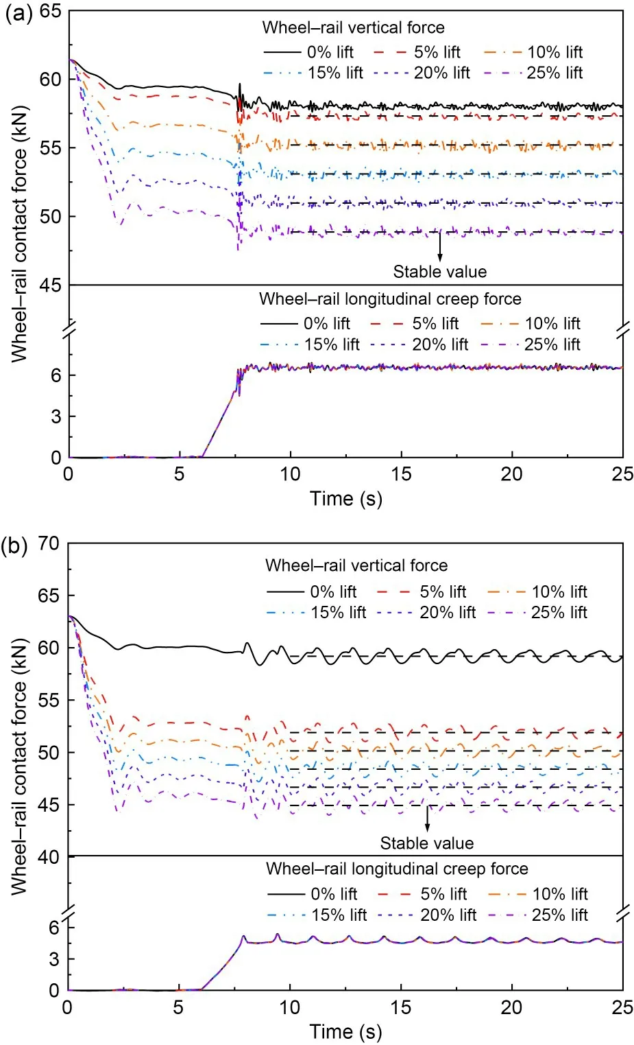
Fig.7 Wheel-rail contact forces under different lifts: (a)No.4 vehicle; (b) No.8 vehicle
Substituting these values in Table 4 into the relationship between available adhesion and wheel-rail vertical force described in Fig.5,the available adhesion under the corresponding working conditions can be obtained by linear interpolation calculation.The specific results are shown in Fig.8.At the typical train speed of 450 km/h,the wheel-rail available adhesions of No.4 and No.8 vehicles are reduced with the increase of aero-wing lift under the direct influence of the wheel-rail vertical force.Under the 0% lift condition,the wheel-rail available adhesions of No.4 and No.8 vehicles are 12.33 kN and 12.57 kN,respectively.When the aero-wing lift accounts for 5%,10%,15%,20%,and 25% of the car body weight respectively,compared with the simulation result of 0% lift condition,the wheel-rail available adhesion of No.4 vehicle decreases by 0.15 kN,0.57 kN,0.99 kN,1.42 kN,and 1.84 kN,with the reduction amplitude accounting for about 1.2%,4.6%,8.1%,11.5%,and 14.9%,respectively,while the wheel-rail available adhesion of No.8 vehicle decreases by 1.45 kN,1.80 kN,2.16 kN,2.51 kN,and 2.87 kN,with the reduction amplitude accounting for about 11.5%,14.3%,17.2%,20.0%,and 22.8%,respectively.It can be found that the variation law of the wheel-rail available adhesion with the aero-wing lift is similar to that of the wheel-rail vertical force.The available adhesion decreases approximately linearly with the increase of lift under the simulation conditions with aero-wing lift.The utilized adhesion remains almost unchanged with the increasing lift because the wheelset does not idle or slide under the current simulation conditions,so the utilized adhesion is dominated by the braking characteristics of the train and its value is almost equal to the braking force.Since the utilized adhesion remains constant under various lift conditions,the variation law of the adhesion margin with aero-wing lift is almost the same as the available adhesion.
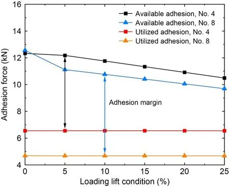
Fig.8 Wheel-rail available adhesion and utilized adhesion vs.lift level
4.3 Influence of train speed on wheel-rail adhesion
The train speed is a comprehensive factor affecting the friction characteristics of wheel-rail contact interface and train braking operation.The effect of train speed on wheel-rail contact forces is discussed under the typical 25% lift condition,as shown in Fig.9.It can be seen that although the aero-wing lift is the same at all speeds,the wheel-rail vertical force of the unloading wheelset still decreases with the increase of train speed,because the load transfer between wheelsets caused by larger aerodynamic moment at higher speed is more remarkable.However,the negative lift force applied to No.4 vehicle partly offsets the load reduction effect of the wheelset while the positive lift force on No.8 vehicle promotes this effect,resulting in a larger reduction in the wheel-rail vertical force of the No.8 vehicle than that of the No.4 vehicle.The utilized adhesion,which is the wheel-rail longitudinal creep force,increases linearly in the braking torque loading stage,and then tends to be stable.As No.4 vehicle is a motor car,the wheel-rail utilized adhesion decreases with the increase of speed,while No.8 vehicle is a trailer and the utilized adhesion is basically constant with the change of train speed when the wheelrail adhesion is not saturated.

Fig.9 Wheel-rail contact forces at different speeds: (a)No.4 vehicle; (b) No.8 vehicle
The results of wheel-rail available adhesion calculated by linear interpolation of the above wheelrail vertical forces and the utilized adhesion are extracted into Fig.10.When the train speed is increased from 350 km/h to 400 km/h,450 km/h,500 km/h,and 550 km/h respectively,the available adhesion of No.4 vehicle is reduced by about 2.5%,4.8%,7.0%,and 9.0%,while that of No.8 vehicle is reduced by about 4.8%,10.2%,15.6%,and 21.0%,respectively,from which we can see that the wheel-rail available adhesion basically decreases linearly with the increase of the train speed.It should be noted that for No.4 vehicle,the differences between the stable values of wheel-rail vertical force at different speeds seem to be small,especially at 350 km/h and 400 km/h,which is quite inconsistent with the change law of available adhesion with speed.The reason for this seemingly contradictory situation is that the available adhesion is also affected by the dynamic friction coefficient that decreases with increasing speed.The wheel-rail utilized adhesion is still dominated by the braking characteristics of the train,while the utilized adhesion of No.4 vehicle is negatively correlated with the train speed and that of No.8 vehicle is not affected by the speed change.Since the change rates of available and utilized adhesions of No.4 vehicle with the increase of speed are similar,the adhesion margin under each speed level is basically the same,while that of the No.8 vehicle decreases linearly with train speed because of the constant utilized adhesion,similar to the change law of the available adhesion with train speed.
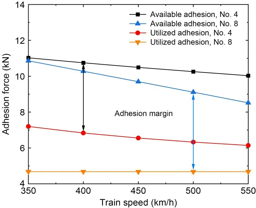
Fig.10 Wheel-rail available adhesion and utilized adhesion vs.train speed
4.4 Coupled influence of aero-wing lift and train speed on wheel-rail adhesion
In this section,the results of wheel-rail available adhesion and adhesion margin under all aero-wing lift and train speed levels are integrated.Fig.11 reflects the coupled influence of aero-wing lift and train speed on wheel-rail available adhesion,with the surface reflecting the utilized adhesion also marked.It is evident that the effects of train speed on the available adhesion are variable under different lift conditions.For No.4 vehicle,when the train speed is increased from 350 km/h to 550 km/h,the wheel-rail available adhesion will reduce by 10.8% under 0% lift condition and basically 9.0% under other lift conditions,indicating that under the cases with aero-wing lift,the different magnitudes of such lift have little impact on the change law of available adhesion with train speed.For No.8 vehicle,the corresponding reductions of wheel-rail available adhesion are 12.0%,19.9%,20.3%,20.7%,21.1%,and 21.6% under the six lift conditions respectively,increasing slightly with larger aero-wing lift.The main reason is that,for No.4 vehicle,the change of wheel-rail vertical force caused by the increase of speed is very weak,so the percentage reduction of available adhesion is only related to the ratio of the variable friction coefficient at different speeds,and has little to do with the aero-wing lift; for No.8 vehicle,the difference between wheel-rail vertical forces at the speeds of 350 km/h and 550 km/h is large,and the available adhesion decreases with increasing aero-wing lift,so the percentage reduction will slightly increase.

Fig.11 Coupled influence of aero-wing lift and train speed on available adhesion: (a) No.4 vehicle; (b) No.8 vehicle
Meanwhile,the effects caused by the increase of aero-wing lift are dependent on the train speed.For No.4 vehicle,the wheel-rail available adhesion under 25% lift condition will reduce by 15.7%,15.3%,14.9%,14.5%,and 14.0% respectively compared with that under 0% lift condition at the speeds of 350,400,450,500,and 550 km/h,meaning that the weakening effect of aero-wing lift on wheel-rail adhesion decreases with the increase of train speed.However,for No.8 vehicle,the law of the available adhesion reduction varying with the speed is just the opposite.The wheel-rail available adhesions are reduced by about 19.0%,20.8%,22.8%,25.2%,and 27.8% respectively and the weakening effect of aero-wing lift on adhesion is enhanced.The main reason for this law is that the aerodynamic lift force and pitching moment applied to the car body are proportional to the square of the train speed.For No.4 vehicle,although the larger pitching moment leads to more load transfer between bogies and lower wheel-rail vertical force under all lifting conditions,the increased negative lift force under 25% lift condition is much larger than that under 0% lift condition and partially offsets the effect of load reduction caused by pitching moment,resulting in smaller reduction of wheel-rail vertical force caused by aero-wing lift at higher train speed,as is the reduction of available adhesion.For No.8 vehicle,both pitching moment and positive lift force will reduce the wheel-rail vertical force of the unloading wheelset,and the effect is more notable under 25% lift condition and increases with the increase of speed,resulting in larger reduction of wheel-rail available adhesion at higher speed.
Fig.12 shows the coupled influence of aero-wing lift and train speed on the wheel-rail adhesion margin,with the surface representing the safety limit marked.It can be seen that under different aero-wing lift conditions,the variation law of the wheel-rail adhesion margin of No.4 vehicle with the train speed is not consistent.Under 0% lift condition,the adhesion margin decreases monotonically with increasing speed while under other lift conditions,the adhesion margin first increases and then decreases with increasing speed,but the change range of adhesion margin is so small that the wheel-rail adhesion margin can be regarded as a constant value.This results in a smaller reduction in adhesion margin caused by increasing aero-wing lift at higher train speeds.The wheel-rail adhesion margin under 25% lift condition will reduce by 34.9%,33.2%,31.8%,30.7%,and 29.6% respectively compared with that under 0% lift condition at the speed of 350,400,450,500,and 550 km/h.For No.8 vehicle,the variation law of the wheel-rail adhesion margin (referred to the difference between available adhesion and utilized adhesion) with aero-wing lift and train speed is very similar to that of the available adhesion.Because the wheel-rail adhesion force has not reached saturation under all current operating conditions,the wheelrail utilized adhesion of No.8 vehicle is almost the same as the reference braking force of the trailer (constant value).The increase of train speed under the greater lift conditions and the increase of aero-wing lift at greater train speed will both lead to a larger decrease in the adhesion margin.

Fig.12 Coupled influence of aero-wing lift and train speed on adhesion margin: (a) No.4 vehicle; (b) No.8 vehicle
Overall,the wheel-rail adhesion margin is significantly higher than the limit of 0 kN within the current range of train speed and aero-wing lift.For No.4 vehicle,the ratio of the wheel-rail adhesion margin to the available adhesion is 35%-47%,while for No.8 vehicle,the value is 45%-65%,which reflects that the wheelrail adhesion margin is always at a relatively sufficient level.At the same time,it means that the maximum tangential force that can be transmitted between the wheel and rail under the current conditions can still meet the further improvement of the train braking force and ensure the operational safety of the train.
4.5 Influence of contact condition on wheel-rail adhesion
As illustrated in Section 4.4,the wheel-rail available adhesion is significantly greater than the utilized adhesion under dry contact condition,and fully meets the requirement of the normal braking of trains.Because the wheel-rail system is generally in an open environment,the wheel-rail contact interface will inevitably be polluted by a ‘third-body medium’ such as rain and engine oil (Arias-Cuevas,2010),which can notably reduce the wheel-rail adhesion performance and then affect the transmission of braking force between the wheel and rail.
Fig.13 shows the influence of wheel-rail contact conditions on wheel-rail available adhesion under different aero-wing lift and train speed conditions,in which the gray surface represents the reference value of the braking force.The influence of aero-wing lift and train speed on wheel-rail available adhesion under wet and greasy contact conditions is similar to that under dry contact and,due to the change of static friction coefficient at the wheel-rail interface,the wheel-rail available adhesions under wet and greasy contact conditions decrease by 41% and 63% respectively compared with that under dry contact condition,making the wheel-rail adhesion level inadequate to meet the normal braking requirement under some operational conditions.Under wet contact condition,the unloading wheelset of No.4 vehicle first reaches adhesion saturation under low-speed and high-lift conditions,while the unloading wheelset of No.8 vehicle can still fully transmit the tangential force required for braking.Under greasy contact condition,for No.4 vehicle,the wheelrail available adhesion is lower than the reference value of the braking force,and for No.8 vehicle,the wheelrail adhesion is not saturated only when the train speed is 350 km/h and 400 km/h with no aero-wing lift.
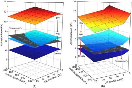
Fig.13 Influence of contact conditions on wheel-rail available adhesion: (a) No.4 vehicle; (b) No.8 vehicle.References to color refer to the online version of this figure
Fig.14 shows the variation of wheel-rail adhesion margin with aero-wing lift and train speed under different contact conditions.For No.4 vehicle,since the change rate of available adhesion with speed is lower than that of braking force under wet and greasy contact conditions,the adhesion margin increases monotonically with the increase of speed,different from that under dry contact condition.The effect of aero-wing lift on adhesion margin is similar to that under dry contact condition and the lower train speed leads to greater reduction of adhesion margin caused by the increase of aero-wing lift.For No.8 vehicle,because the braking force remains unchanged,the wheel-rail adhesion margin is negatively correlated with the aero-wing lift and train speed.Taking 0 kN as the safety limit of the adhesion margin,and assuming that the data points of each operation condition vary linearly,the operating safety curves of No.4 vehicle under wet contact condition and No.8 vehicle under greasy contact condition can be obtained,as shown in Fig.15.Under wet contact condition,within the current operation speed range,only when the aero-wing lift force does not exceed 10.9% of the car body weight,can the train run safely on the premise of maintaining the current braking capacity.Under greasy contact condition,it is possible to maintain the braking force unchanged and prevent the trailer wheelset from sliding by adjusting the magnitude of aero-wing lift only when the train speed does not exceed 443 km/h.For motor cars (middle car),it is no longer possible to adjust the magnitude of aero-wing lift to avoid wheelset sliding.Therefore,in general,reducing the braking torque or sanding and other friction enhancement methods are necessary to restore the normal braking operation of the train.
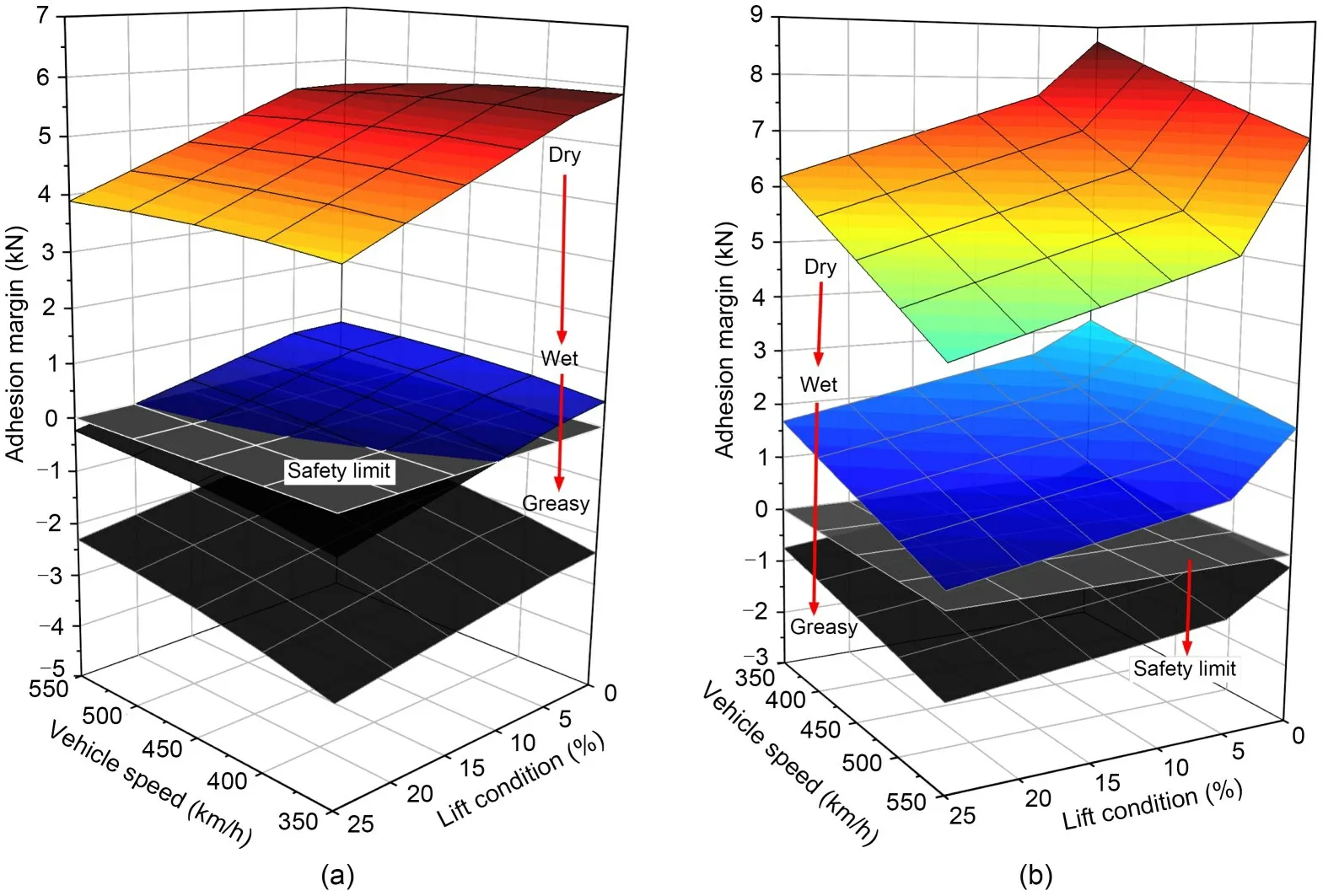
Fig.14 Influence of contact conditions on wheel-rail adhesion margin: (a) No.4 vehicle; (b) No.8 vehicle

Fig.15 Train operation safety curves under different contact conditions: (a) wet; (b) greasy
4.6 Influence of track irregularity on wheel-rail adhesion
It is known that,as a typical disturbance in the wheel-rail interface,track irregularity will significantly affect the wheel-rail dynamic interactions during the actual operation of high-speed trains.Thus,this subsection investigates the effect of track irregularity on the wheel-rail adhesion performance.Considering that the new high-speed train with aero-wings should be suitable for current high-speed railway lines,we took the ballastless track profile irregularity of China’s highspeed railway as the model input and selected the simulation case of the train operating braking under wet contact condition for analysis.It should be noted that due to the existence of track irregularity,the wheelrail contact force will fluctuate greatly and the lateral and yaw angle displacements of the wheelset will be non-negligible,resulting in changes of wheel-rail contact position.The assumption of constant shape of the contact patch and the Kalker creep coefficient is no longer applicable.In order to obtain the wheel-rail available adhesion,it is necessary to extract the results of the wheel-rail vertical force,the length and width of contact patch,and the Kalker creep coefficient of each simulation sampling point for calculation.
Comparisons of wheel-rail vertical force and wheel-rail available adhesion of the unloading wheelset with and without track irregularity at the speed of 350 km/h and 10% lift condition are illustrated in Fig.16.It can be seen that the response curve of wheelrail available adhesion is similar to that of wheel-rail vertical force because the wheel-rail available adhesion is proportional to the wheel-rail vertical force.Without considering the effect of track irregularity,wheel-rail available adhesion can be basically stabilized near a certain value after the loading of aerodynamic load and braking torque.When track irregularity is considered,the wheel-rail vertical force will fluctuate obviously,which further leads to great fluctuation of the wheel-rail available adhesion.However,the average values of the wheel-rail available adhesion of No.4 and No.8 vehicles within 10-25 s simulation time are 7.236 kN and 6.997 kN,respectively,which are almost the same as those when track irregularity is not considered: 7.238 kN and 6.999 kN,respectively.The same is true for wheelrail utilized adhesion,as can been seen in Fig.17.
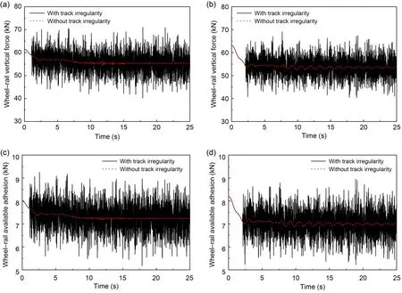
Fig.16 Comparison of wheel-rail vertical force and wheel-rail available adhesion of the unloading wheelset with and without track irregularity: (a) wheel-rail vertical force of No.4 vehicle; (b) wheel-rail vertical force of No.8 vehicle;(c) wheel-rail available adhesion of No.4 vehicle; (d) wheel-rail available adhesion of No.8 vehicle
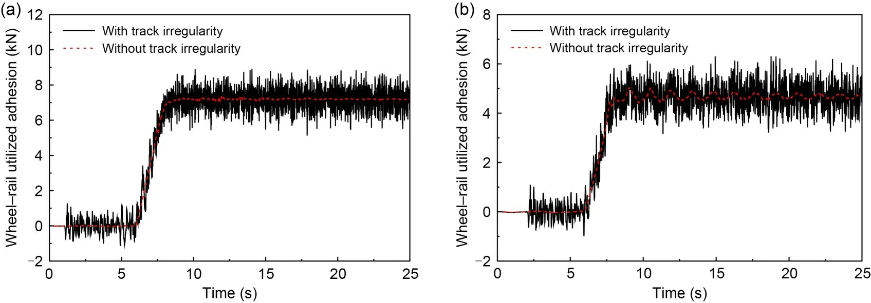
Fig.17 Comparisons of wheel-rail utilized adhesion of the unloading wheelset with and without track irregularity:(a) No.4 vehicle; (b) No.8 vehicle
When considering track irregularity and taking the mean value of wheel-rail available adhesion as a quantity and referring to the evaluation process of wheel-rail adhesion performance above,the wheelrail adhesion levels under different train speeds and aero-wing lift conditions can be calculated.Then the train operation safety curve under wet contact condition similar to those in Section 4.5 can also be obtained as shown in Fig.18.It can be seen that the operating safety curve when the track irregularity is considered is very close to that when the track irregularity is not considered.To further verify the reliability of the result and take into account possible calculation errors,10 operating cases with aero-wing lift within 5% error range above and below the safety curve were selected for verification at five speed levels (350,400,450,500,and 550 km/h),which are shown in Table 5.

Table 5 Simulation cases for verification at five speed levels
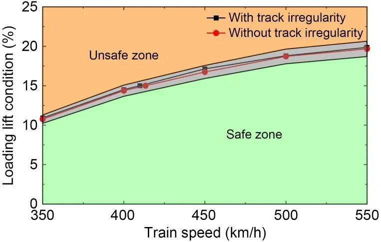
Fig.18 Comparisons of train operation safety curves with and without track irregularity
Fig.19 shows the wheel-rail longitudinal creepage under different simulation cases,and we can see that when the aero-wing lift is slightly less than the corresponding value of the safety curve,the wheel-rail longitudinal creepage increases with the braking force loading and then basically stabilizes around a constant value.However,when the aerodynamic lift is slightly greater than the corresponding value of the safety curve,the wheel-rail longitudinal creepage will keep increasing,which means that the wheel slides,and the difference between the circumferential velocity and the translational velocity of the wheel keeps increasing.In addition,it can be seen that wheel-rail longitudinal creepage is higher when track irregularity is considered,especially under the case of wheel slides,when the wheel-rail longitudinal creepage surges at an earlier time.This indicates that track irregularity has a certain weakening effect on wheel-rail longitudinal adhesion force,which may be due to the fact that there is an element of lateral creep in the total creep,leading to a decrease in the tangential force that can be transmitted in the longitudinal direction.However,within the error tolerance,judging whether the wheel slides from the simulation results is completely consistent with the results given by the safety curve,so the existence of track irregularity does not change the judgment result of whether the wheel-rail available adhesion can satisfy the normal traction transfer,and has little influence on the evaluation of wheel-rail adhesion performance.

Fig.19 Comparisons of wheel-rail longitudinal creepage with and without track irregularity: (a) 350 km/h,10.22% lift;(b) 350 km/h,11.30% lift; (c) 400 km/h,13.65% lift; (d) 400 km/h,15.09% lift; (e) 450 km/h,15.91% lift; (f) 450 km/h,17.58% lift; (g) 500 km/h,17.78% lift; (h) 500 km/h,19.65% lift; (i) 550 km/h,18.69% lift; (j) 550 km/h,20.65% lift
5 Conclusions
A comprehensive dynamic model of high-speed trains with aero-wings was developed to obtain the wheel-rail contact force under various aerodynamic loads.The evaluation method of adhesion performance was established and the relationship between available adhesion and wheel-rail vertical force and train speed was obtained based on the description of wheelrail adhesion characterized by the Polach model.The wheel-rail adhesion performance under different contact conditions was obtained by MBD simulations.Based on the main assumptions that wheel-rail adhesion characteristics were calculated by the Polach model and the train’s aerodynamic coefficients remain constant at different speeds,conclusions can be drawn as follows:
1.Under the action of aerodynamic load and braking torque,the load transfer occurs on all four wheelsets and the one with the most load reduction has the lowest adhesion performance.
2.The wheel-rail available adhesions of both motor car and trailer decrease with the increase of aerowing lift and train speed under all contact conditions and the effects of aero-wing lift and train speed are coupled.The adhesion margin is simultaneously dominated by the available adhesion and braking characteristics of the train,showing differences with the change of contact conditions.
3.The pollution from a ‘third-body medium’,such as water and oil on the wheel-rail interface,reduces the wheel-rail adhesion performance dramatically and results in the unloaded wheelset reaching adhesion saturation under some operational conditions.The train operation safety curves are given and,based on these,measures such as limiting the aero-wing lift and train speed,reducing the braking torque,and sanding are proposed.
4.Within a certain error range,the track irregularity only weakly affects the evaluation of wheel-rail adhesion performance.
Acknowledgments
This work is supported by the National Key Research and Development Program (No.2020YFA0710902) and the National Natural Science Foundation of China (No.11772275).
Author contributions
Lin JING designed the research.Yang CHEN processed the corresponding data and wrote the first draft of the manuscript.Tian LI,Liang LING,and Kaiyun WANG helped to organize the manuscript.Lin JING revised and edited the final version.
Conflict of interest
Yang CHEN,Lin JING,Tian LI,Liang LING,and Kaiyun WANG declared no potential conflicts of interest with respect to the research,authorship,and publication of this article.
Data availability statement
The data used to support the findings of this study are available from the corresponding author upon request.
杂志排行
Journal of Zhejiang University-Science A(Applied Physics & Engineering)的其它文章
- Research on the sampling performance of a new bionic gravity sampler
- Effects of potassium channel blockage on inverse stochastic resonance in Hodgkin-Huxley neural systems
- Vibration suppression of composite panel with variable angle tow design and inerter-based nonlinear energy sink
- Co3O4-ZnO/rGO catalyst preparation and rhodamine B degradation by sulfate radical photocatalysis
- Determination of the dynamic characteristics of locomotive drive systems under re-adhesion conditions using wheel slip controller
