Damage assessment of aircraft wing subjected to blast wave with finite element method and artificial neural network tool
2023-07-31MengtaoZhangYangPeiXinYaoYuxueGe
Meng-tao Zhang,Yang Pei,Xin Yao,Yu-xue Ge
School of Aeronautics, Northwestern Polytechnical University, Xi'an, 710072, Shaanxi, China
Keywords:Vulnerability Wing structural damage Blast wave Battle damage assessment Back-propagation artificial neural network
ABSTRACT Damage assessment of the wing under blast wave is essential to the vulnerability reduction design of aircraft.This paper introduces a critical relative distance prediction method of aircraft wing damage based on the back-propagation artificial neural network (BP-ANN),which is trained by finite element simulation results.Moreover,the finite element method (FEM) for wing blast damage simulation has been validated by ground explosion tests and further used for damage mode determination and damage characteristics analysis.The analysis results indicate that the wing is more likely to be damaged when the root is struck from vertical directions than others for a small charge.With the increase of TNT equivalent charge,the main damage mode of the wing gradually changes from the local skin tearing to overall structural deformation and the overpressure threshold of wing damage decreases rapidly.Compared to the FEM-based damage assessment,the BP-ANN-based method can predict the wing damage under a random blast wave with an average relative error of 4.78%.The proposed method and conclusions can be used as a reference for damage assessment under blast wave and low-vulnerability design of aircraft structures.
1.Introduction
In modern war,aircraft are high-value military targets mainly threatened by air-to-air and surface-to-air missiles [1].The shock wave from the missile warhead detonation is one of the main damage mechanisms against the airfoil structure of the wing,the tail,and the canard,which provides important functions for the aircraft.Damaged airfoil structure will affect the performance of aircraft tasks and even lead to a crash [2,3].Researches on the dynamic response and damage characteristics of simple structures such as panel,stiffened plate and I-beam under blast loading have been carried out [4-8],and various blast resistant structures and materials have been developed[9-11].Regarding the blast damage of military targets,most of the studies is on ships[12,13],armored vehicles [14,15],and military buildings [16,17].Damage characteristics and damage assessment method of aircraft wing subjected to blast wave is less studied.
In terms of aircraft damage assessment method,existing studies[18,19] consider the fragment damage and the blast wave damage as two independent steps of damage assessment due to their different damage characteristics.In order to study the blast damage characteristics of the aircraft,Masi et al.[20]introduced a dynamic response simulation method of aircraft fuselages subjected to internal explosions.Both the gravity and the pressurization load at the cruising altitude were considered in the simulation.Kotzakolios et al.[21] simulated the blast response of metal and composite laminate fuselage structures and proposed a vulnerability index for different loads.Han et al.[22] obtained the kill criterion by modeling and assessing the structure vibration of aircraft components with the simplified elastic-plastic method.Marzocca et al.[23] studied the aeroelastic response to the time-dependent external blast load of a two-dimensional rigid/elastic-lifting surface.The damage assessment of aircraft structure by fragments[24]and the coupling damage effect between the two damage mechanisms [25,26] can be studied independently.While this paper mainly focuses on the damage assessment of aircraft wing structure subjected to blast wave.
In terms of functional damage assessment of the wing,Pei et al.[3] simulated the aerodynamic performance degradation of the wing with the hole damage and proposed an survivability analysis method regarding the size and location of the hole.Krishnamurthy[27] presented an equivalent plate analysis technique to estimate the frequency response and the flutter speed of an aircraft wing with damage.Feng et al.[28] proposed a damage criterion of the wing according to the strength of the aircraft structure.
In terms of damage criteria of blast wave,the overpressure criteria and specific impulse criteria are mainly used in battle damage assessment [29,30].However,most of these criteria are based on tests from years ago and are not suitable for modern military aircraft [31].In addition,the damage of wing structure under blast loading is related to the detonation position,which is difficult to be considered in the conventional criteria.Damage assessment method based on experiment is reliable but costly in money or in computational time.Therefore,it is necessary to develop a high-efficiency damage assessment method that can comprehensively consider all the major factors.
Artificial neural network(ANN)is based on statistical regression and widely used in modeling complex relationships which are physically difficult to explain [32].A remarkable feature of ANN is the potential of gaining knowledge of problems through training and can solve the same kind of problems after adequate training[33].ANN has been developed rapidly over the last few decades,started with the modeling of the functions of human brain by McCulloch and Pits [32],and has been used in modeling of constitutive relationship and prediction of mechanical properties of various materials [34,35].Back-propagation artificial neural network (BP-ANN) is one of the most widely used neural network methods.The objective of BP-ANN is to construct specific mathematical correlations between user-defined inputs and outputs.The trained BP-ANN can predict quickly and has strong generalization ability and nonlinear mapping ability [36].Mahzan et al.[37]developed a BP-ANN-based signal processing method for impact location in composite aircraft wing-box structures.The study shows a good impact location estimation.Recently,there is a significant attempt to use ANN with finite element method (FEM)especially to reduce computational time where an extensive number of FE simulations are required [38].KılıÇ et al.[33] established a FEM-ANN model to determine the ballistic limit thickness of high hardness steels against 7.62 mm armor-piercing bullet.The FEM-ANN model can produce results in seconds,whereas the FE simulations take hours or more.
In this paper,the BP-ANN model based on FE simulations has been established for a rapid damage assessment of wing damage under blast wave.In section 2,the FE model of a typical horizontal tail,which is easier to test because of its smaller size,is built and the simulation method has been validated by static explosion damage tests of bare charge on the ground.In section 3,simulations of a typical wing structure,which has a more obvious regularity of blast wave damage because of its larger size,has been carried out.A series of dynamic response simulations of the wing structure under blast loading were carried out regarding the equivalent charge,strike area,strike azimuth,and relative distance.In section 4,a BPANN model to predict the critical relative distance of wing damage is established and trained by the FE simulation results.Fig.1 presents the framework of this paper and the relationship between the sections.The method and conclusions in this paper can be used as a reference for damage assessment of airfoil structures under blast wave and low-vulnerability design of aircraft structures.

Fig.1.Framework of damage assessment of aircraft wing with FEM and BP-ANN tool.
2.FEM and damage test of airfoil structure
In this section,the effectiveness of the FEM for blast wave damage of airfoil structure is validated by damage tests of an allmovable horizontal tail.The FEM based on the Lagrange method and the CONWEP empirical model is presented.Blast wave damage tests of the horizontal tail were carried out by the static explosion of bare charge on the ground.The structural dynamic response of the horizontal tail subjected to the blast wave in the tests is simulated based on LS-DYNA platform.The blast loading,the target damage results,and the characteristic physical quantity (the maximum relative deflection of skin) obtained by simulations and tests are compared to validate the FEM.
2.1.FE model establishment
In FE model,the material is discretized into finite elements in which the conservation and constitutive equations are solved.Different spatial discretization methods correspond to different FEM [39].The most commonly performed discretization methods are Euler,Lagrange,Arbitrary Lagrange Euler(a mixture of Lagrange and Euler),and Smooth Particles Hydrodynamics (SPH).KılıÇ [40]presented a comparative study to demonstrate applicability of Lagrange and SPH methods on determination of impact response of metallic structures and concluded that,the Lagrange method is more effective in simulating the deformation pattern of target.The finite element moves with the material in the Lagrange method,which is ideal for tracking the motion and deformation in regions with relatively low deformation and possible large displacement.The Lagrange method is extensively used because of its advantages,such as being able to track accurately material boundaries and integrate complicated material models.Conservation of mass is automatically satisfied in the Lagrange method and material interfaces are defined precisely.The disadvantage of Lagrange is that the finite element can become heavily distorted in a deformation region,which can result in negative effects on the accuracy and increases the computation cost.
The FE models of airfoil structures in this paper(horizontal tail and wing of aircraft) are established based on LS-DYNA numerical simulation software.The airfoil structures in this paper are metal thin-walled structures.The majority part of the structure are modeled by the Belytschko-Tsay shell elements with 2 integration points through shell thickness.The joints are meshed with the constant stress hexahedron solid elements.All elements are discretized with the Lagrange method.The element size is selected according to the size of the structure and the convergence of the calculation results.The boundary constraints of models are set by constraining the degrees of freedom of corresponding nodes.
2.2.Material model
Appropriate material models is the key to describe the deformation and failure law of materials.The Johnson-Cook model is commonly used in high-velocity impact studies.It is a visco-plastic model for ductile metals and uses strain hardening,strain rate,and thermal softening effects on material behavior and fracture [41].Both Johnson-Cook constitutive model and failure model are adopted in this paper to simulate the elastic-plastic behavior and ductile fracture of airfoil structures under the blast loading.The Johnson-Cook constitutive model is as Eq.(1)
According to the cumulative damage law,the damage of each element is expresses as a variableDbetween 0 and 1 as
where Δε is the increment of the plastic strain during an integration cycle and εfis the equivalent strain to fracture under the current conditions of stress,strain rate and temperature.When D=0,the element is undamaged.When D=1,the element is failure.
The general expression for strain at fracture is given as
whereD1-D5are material failure parameters.
2.3.Load blast wave in simulation
To simulate the blast shock wave loading,the CONWEP empirical model is used.The CONWEP model was established on the basis of the distribution characteristics of shock wave loads on the plate produced by explosives in free field and ground [42].It accounts for angle of incidence by combining the reflected pressure(normal-incidence) value and the incident pressure (side-on-incidence) value.The pressure can be calculated by the following equation
wherePloadis the actual pressure on the element surface,α is the angle of incidence,Pincidentis the incident pressure,andPreflectedis the reflected pressure.
The CONWEP method is not applicable to the simulation of contact explosion or close-range explosion problems,and a clear loaded surface is required for the target.This method has the following advantages:
(1) This method does not consider the influence of air medium on shock wave propagation;
(2) This method does not require an Euler field,and the stability of the algorithm is better;
(3) For complex problems,using this method to build and calculate models can greatly reduce the calculation cost.
The keyword *LOAD_BLAST_ENHANCED (algorithm is CONWEP)in LS-DYNA is used to simulate the blast loading in this paper.The simulated blast loading can be adjusted by modifying charge parameters and position parameters of the keyword.
2.4.Design of the damage test
The test target of a horizontal tail is designed based on the theory of aircraft structure design [43].As shown in Fig.2(a),it is mainly composed of four parts: skins,spars,ribs,and joints.The structure layout of the test target is a typical thin skin multi-spar structure.The material of the test target is 2024-T3 high-strength aluminum alloy which is one of the most widely used materials in aircraft structure,and the thickness of the skin is 1.5 mm.Riveting is the main method of connection between parts of the test target,and welding is also used as an auxiliary method in some positions.The target weight 47 kg.

Fig.2.Design and processing of test target: (a) Model of test target;(b) Photo of test target.
Blast damage tests of the horizontal tail test targets were carried out by static explosion of bare charge on the ground.The test site was chosen to be in an open and flat hard soil area within the test range.16 kg bare cylindrical charge of TNT was used as test charge and the size of the charge is Ф 250 mm×200 mm.During the test,the charge was suspended on a hanger 1.5 m above the ground for detonation.According to the explosion similarity law,there is a functional relationship between the peak value of shock wave overpressure Δpmand the scaled distanceZ,andZis expressed as Eq.(5) [8].
whereris the distance to the explosion center,Mis the equivalent charge of TNT.
Three tests were carried out using three sets of identical charges and targets under the test conditions shown in Table 1.The target positions are selected according toZ.

Table 1 Test conditions setting.
The target was mounted on a customized bracket through three sets of articulated joints and the bracket was fixed on the ground.As shown in Fig.3(a),the normal direction of the upper surface of the target was adjusted horizontally and pointed to the explosion center.In this way,the actual mounting connection of horizontal tail on the aircraft is simulated.After the test,damage results of the target structure and the mounting joint were recorded.

Fig.3.Installation of test target: (a) Installation attitude;(b) Articulated joints.
Pressure sensors were arranged on the ground in the direction of two 90°rays radiating from the explosion center.Eight radii of measuring points are selected according toZ,corresponding toZof 1 m kg-1/3,1.5 m kg-1/3,2 m kg-1/3,2.5 m kg-1/3,3 m kg-1/3,4 m kg-1/3,5 m kg-1/3,6 m kg-1/3,respectively.The schematic diagram of the test layout is shown in Fig.4.

Fig.4.Schematic diagram of the test layout.
113 B series piezoelectric pressure sensors (United States PCB Company)with measuring range of 0-68 MPa are used to measure shock wave pressure on the ground.The resonant frequency of the sensor is ≥500 KHz,the rising front is ≤1 μs,the non-linearity is≤±1%F·S,and the sensor has built-in speed compensation module,which can effectively suppress parasitic output caused by shock acceleration.
The FE model of the tail test target is shown in Fig.5.The size of the FE model is consistent with the physical size of the tail.Except that the joints are modeled by solid elements,the other parts of the target and bracket are modeled by shell elements.All elements adopt the Lagrange method and the element size is 1-2 cm.The boundary condition of the model is the fixed support of the nodes at the bottom of the bracket.The keyword*CONTACT_TIEBREAK_NODES_TO_SURFACE is set to simulate the connection and failure between parts of the tail.The keyword*CONTACT_AUTOMATIC_SINGLE_SURFACE is set to simulate the contacts between parts of the tail.
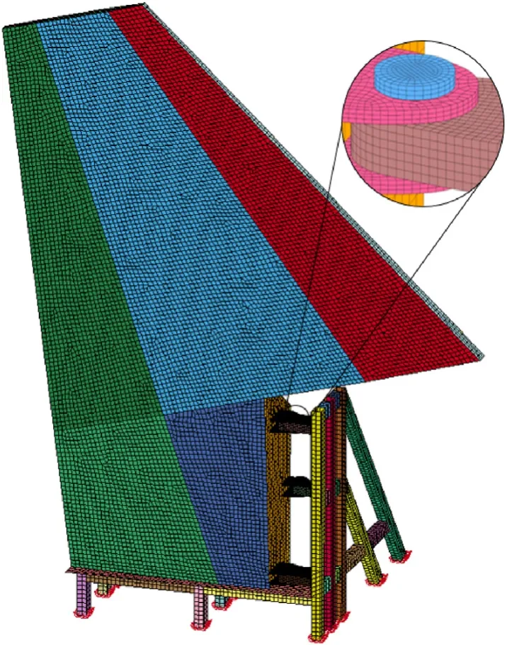
Fig.5.Finite element model of tail target.
The materials of the tail target and the bracket are 2024-T3 aluminum alloy and Q235 steel,respectively.The material parameters of the materials used in the simulation are obtained from Refs.[44,45] and are summarized in Table 2,whereEis the elastic modulus of the material and μ is the poisson's ratio of the material.
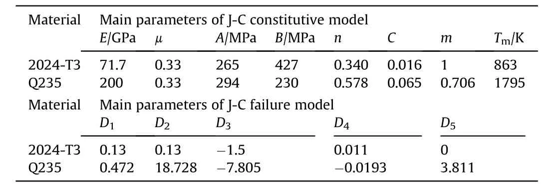
Table 2 Main parameters of Johnson-Cook model of 2024-T3 and Q235[44,45].
2.5.Test and simulation results of overpressure and specific impulse
At eachr,2-6 groups of overpressure time history data Δp(t)have been recorded.The specific impulseIis calculated as [29].
whereT+is the duration of positive pressure of shock wave.
The mean values of ΔpmandIare shown in Fig.6.The attenuation ratio ofIregardingris more gentle than Δpm,because of the increasingT+.

Fig.6.Test results of peak overpressure Δpm and specific impulse I regarding r: (a) The peak overpressure Δpm with r;(b) The specific impulse I with r.
The blast loading on target surface under the test conditions is simulated based on the CONWEP method.For Test 1 (r=7.56 m),the contour of the incident overpressure simulated on the upper surface of the target at the time of 1 ms after the shock wave reaches is shown in Fig.7(a).The time history curve of the simulated blast loading at the center of the surface on the target in Test 1 is shown in Fig.7(b).

Fig.7.Simulation of the blast loading on target surface in Test 1: (a) Distribution of Δp on the upper surface;(b) Δp(t) at the center of the upper surface.
As shown in Fig.8,the simulation results of the peak overpressure at eachrof sensors in the tests based on the CONWEP method are compared with the test results.According to the diagram,the error between the peak overpressure of simulated blast loading and the test results is small whenris larger than 7.56 m.This study does not involve near-range or contact explosion problems,therefore the accuracy is enough by using the blast loading model based on the CONWEP method.
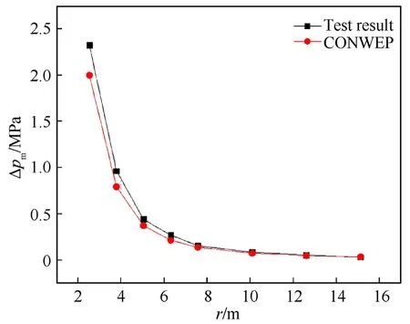
Fig.8.Comparisons of simulated peak overpressure Δpm with test measurements.
2.6.Test and simulation results of the structure damage
The damage of target 1 in Test 1 is shown in Fig.9.Under the blast loading,the whole target broke along the rear spar connection,and some connections at other locations also failed.In addition,the upper surface skin of the target had different degrees of plastic deformation.The deformation at the rear of the tail root section is the most serious.The maximum relative deflection of the skin was measured to be 55 mm.

Fig.9.Damage to target 1 after Test 1.
The damage of target 2 in Test 2 is shown in Fig.10(a).The upper surface skin at the rear of the root segment had obvious plastic deformation.The maximum relative deflection of the skin was measured to be 25 mm.In addition,the connection in the local area of the target was slightly warped.The target 3 after Test 3 is shown in Fig.10(b).There is no obvious damage to the target.
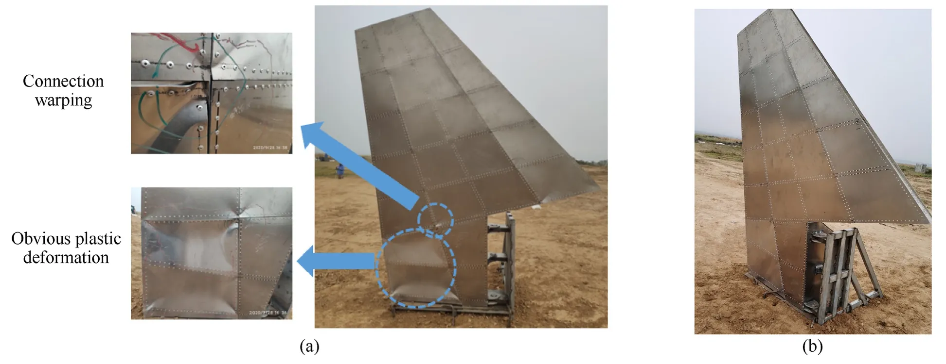
Fig.10.Damage to targets after (a) Test 2 and (b) Test 3.
After the three tests,the targets showed different damage degrees,but there are two main damage modes: 1) Connection failure,2) Structural plastic deformation.After the tests,no obvious damage was observed in the joints of the targets,indicating that the horizontal tail joints would not be damaged before the main structures under blast loading.
Fig.11 presents the simulation and the test results of the target damage in the three tests.The simulation result of Test 1 is shown in Fig.11(a),the connection of the target mainly breaks along the rear spar,which is consistent with the test results.The maximum relative deflection of the target skin obtained by simulation is 47 mm,and the error between the simulation and the test result(55 mm) is 15%.For Test 2,the simulated maximum relative deflection of the skin is 22 mm with an error of 8% from the test measurement of 25 mm,as shown in Fig.11(b).For Test 3,the simulation result shows that no obvious plastic deformation or other damage has occurred to the target,which is consistent with the test result,as shown in Fig.11(c).Therefore,the blast wave damage simulation method of airfoil structure based on CONWEP model is effective,which can be used to carry out the subsequent simulation of wing blast wave damage.

Fig.11.Comparisons of the simulation results and the test results: (a) Test 1;(b) Test 2;(c) Test 3.
3.Data generation and analysis of FE simulations
Based on the validated modeling and simulation method,a FE simulation model of a typical aircraft wing structure is established to study the dynamic response of the wing structure under blast loading.The judgment process and criteria of different damage modes of wing structure subjected to blast wave are proposed.And the simulation calculation and damage judgment have been conducted for different equivalent charge,strike area,strike azimuth and relative distance.
3.1.Model of wing structure
The FE model of a typical high aspect ratio wing is established as shown in Fig.12.Similar to the horizontal tail,the wing has a typical thin skin multi-spar wing structure,mainly composed of the skin,5 spars and 22 ribs.All parts are modeled by shell elements with the size of 5-10 cm,and the number of elements is 3.8 thousand.The material of the wing structure is 2024-T3 aluminum alloy,and the skin thickness is 2 mm.Johnson Cook constitutive model and failure model are adopted,and the parameters are as shown in Table 2.The nodes at the root of the spars are fixed as the boundary constraints of the model.The CONWEP method is used for blast loading of simulations.Other settings of the FE model are consistent with the horizontal tail model.

Fig.12.FE model of a typical high aspect ratio wing structure: (a) Shape and dimensions;(b) Internal structure.
The equivalent charge of TNT is represented by the parameterM.A line segment through the midpoint of most wing chords is defined as the baseline and points in this line segment are defined as the base points.The position of the explosion center relative to the wing is defined by three variables,which are the spanwise distance of the base pointL,the azimuth angle of the explosion center θ and the relative distance between the explosion center and the base pointD,as shown in Fig.13.
Fig.13.Explosion center location description and variable definition.
The mesh convergence is evaluated before the calculation of wing structural damage under different blast waves.The simulation condition ofM=50 kg,L=11.3 m,θ=270°,D=7.5 m is selected to analyze the mesh convergence by calculating the average structural deformation.The numbers of elements are 1.1 thousand,1.8 thousand,2.8 thousand,3.8 thousand,5.5 thousand,8 thousand,and 15 thousand.The calculated average structural deformations are illustrated in Fig.14.The results with 3.8 thousand elements are very close to those with more elements.Therefore,it is adequate to obtain relatively accurate results by using 3.8 thousand elements.

Fig.14.Calculated average structural deformation at M=50 kg, L=11.3 m,θ=270°,D=7.5 m with different number of elements.
3.2.Determination of damage
The dynamic response of the wing structure under some typical striking conditions is simulated.The simulation results show that there are two main damage modes of the wing,which are overall structural deformation and local skin tearing.
The dynamic response of the wing under blast wave impact is simulated atM=500 kg,L=18.8 m,θ=270°,D=15 m.The wing structure undergoes a severe overall deformation(mainly bending deformation) as shown in Fig.15.With the increase of the deformation,the wing structure gradually turns to be a plastic state,thus changing the aerodynamic shape of the wing.Consequently,negative effects such as insufficient lift,excessive drag,and reduced efficiency of the control surface may occur and even damage the wing [46].
Fig.15.Severe overall structural deformation of the wing after a blast wave impacts the wing from below.
The dynamic response of the wing under blast wave impact is simulated atM=50 kg,L=3.8 m,θ=0°,D=6 m.The skin on the leading edge of wing root is torn by the blast wave as shown in Fig.16(a).Simulation result atM=200 kg,L=3.8 m,θ=270°,D=8 m is shown in Fig.16(b).The lower skin of the wing root is torn to form holes.Local skin tearing can degrade the aerodynamic characteristics of the wing.And there is a risk that the holes will expand during subsequent flight,eventually leading to wing damage [2].
Fig.16.Local skin tearing at different positions of the wing: (a) Local skin tearing at the leading edge;(b) Local skin tearing at the lower surface.
For the above two damage modes,the average structural deformationSand the total area of holesAare defined as physical quantities of damage.TheScan be calculated as
wherenis the total number of nodes in the model,siis the displacement occurring at theith node.
TheSandAcan be extracted from the dynamic response simulation results of the wing structure under blast wave.The wing structure damage is determined by comparing theSandAwith corresponding damage criterion.For different aircraft wings,the criterion values ofSandAare generally different.The determination of accurate criterion values needs CFD analysis,practical experiment,flight simulation,etc,which is beyond the scope of this study.The values in this paper are empirically selected and shown in Table 3.In practical applications,the criterion values can be set by the user.
Table 3 Criteria for determining impact damage of the metal wing in this study.
For each striking condition,the damage of the wing structure can be determined by comparing the simulation result and the damage criteria.The damage determination process of the wing is shown in Fig.17.When theM,Land,θ are given,Dwill be continuously adjusted in simulation to find the critical relative distanceDcof wing damage.Then the overpressure thresholdPfor the wing blast wave damage can be determined.
Fig.17.Determination of the overpressure threshold P and the critical relative distance Dc.
3.3.FE simulation results
The simulation conditions are set as shown in Table 4.Five groups of typical TNT equivalent are selected to study the effect ofMon wing damage results.Three reference points are set at the root,middle,and tip segment of the wing respectively to study the effect ofLon the results of wing damage.Eight typical azimuth angles are selected in the airfoil section at each base point to study the effect of θ on the wing damage results.The relative distanceDis adjusted according to the process shown in Fig.17.In this study,541 conditions are finally simulated.

Table 4 Conditions of wing blast wave damage simulation.
The simulation results ofPare shown in Table 5.There are two curves in each figure,the blue one shows the incident overpressure threshold regarding the azimuth angle and the red one is about the reflection overpressure threshold.Each ray from the origin represents an azimuth angle and the distance from the intersection of the curve and the ray to the origin represents the overpressure threshold,where the display range of pressure is 0-10 MPa.According to Table 5,the equivalent chargeM,the spanwise distanceL,and the azimuth angle θ all have a significant effect on the overpressure thresholdPof wing damage.

Table 5 Simulation results of P for wing blast wave damage.
3.4.Influences discussion of M on wing damage
The overpressure thresholdPcorresponding to each θ is weighted average for givenMiandLj,and the weight is the proportion of projection area of the wing in the direction of each θ.Then,the weighted average results by θ are averaged byLto get the corresponding overpressure threshold of each equivalent charge,which is expressed as
whereθ=θkis the overpressure threshold in case ofM=Mi,L=Lj,θ=θk,andakis the projection area of the wing at thekth azimuth angle.
The relationship betweenPMandMis shown in Fig.18.It indicates that as theMincreases,both the incident overpressure threshold and the reflected overpressure threshold of wing damage decrease rapidly.
Fig.18.Relationship between PM and M.
There are two main reasons for this phenomenon:(1)An area of the wing surface is defined as the high pressure area,in which the peak incident overpressure at all locations is bigger than 80%of the peak incident overpressure over the entire wing.KeepLand θ constant and when the same Δpmoccurs on the wing surface,the greater theM,the bigger the high pressure area of the shock wave on the wing surface,as shown in Fig.19.
Fig.19.Comparisons of the high pressure area for(a)M=50 kg and(b)M=500 kg.(2)Keep L and θ constant and when the same Δpm occurs on the wing surface,the greater the M,the slower the attenuation of overpressure on the wing surface.Which means the positive pressure duration T+is longer and the specific impulse I on the wing surface is greater,as shown in Fig.20.

Fig.20.Comparison of the attenuation rates and the specific impulse of incident overpressure with M=50 kg and M=500 kg.
When the equivalent chargeMis small,the damage mode of the wing is mainly local skin tearing.And the total energy of the blast wave absorbed by the wing is mainly converted into internal energy due to the deformation and tearing of local structure.WhenMis large,the damage mode is mainly overall structural deformation.Besides the internal energy of the wing,more energy is converted into the kinetic energy of the deformation movement of the wing,as shown in Fig.21.
Fig.21.Comparison of energy conversion of the blast wave absorbed by the wing for (a) M=50 kg and (b) M=2000 kg.
3.5.Influences discussion of L on wing damage
As shown in Fig.22,when the equivalent chargeMis small,there is a large difference between the overpressure thresholdsPat different spanwise distancesLof the wing.The wing is more likely to be damaged by the blast wave at the root segment,followed by the middle segment,and the most difficult to damage the wing at the tip segment.AsMincreases,the difference between the overpressure thresholds for differentLdecreases gradually.If other parameters exceptLremain unchanged andMis large enough,the damage results of the wing are basically the same when the blast wave strikes the different spanwise areas.

Fig.22.Comparison of shock wave overpressure thresholds at different spanwise distances L: (a) Incident overpressure threshold;(b) Reflected overpressure threshold.
There are two main reasons for this phenomenon.(1)As shown in Fig.23,the blast loading is not uniformly distributed over the entire wing surface,especially whenMis small.The difference inLwill affect the high pressure area distribution of the blast loading,and ultimately the dynamic response and damage result of the wing.(2) The spars of the wing in this study are arranged along equal percentage lines.The spacing between adjacent spars decreases gradually from the root to the tip,which makes the skin between the spars at the root more vulnerable to blast wave.

Fig.23.Comparison of high pressure area at different spanwise distances L: (a) M=50 kg, L=3.8 m;(b) M=50 kg, L=11.3 m;(c) M=50 kg, L=18.8 m;(d) M=2000 kg,L=3.8 m;(e) M=2000 kg, L=11.3 m;(f) M=2000 kg, L=18.8 m.
However,with the increase ofM,the damage mode of the wing gradually changes to the overall structural deformation,and the blast loading distribution on the wing surface tends to be uniform.Therefore,the influence ofLon wing damage results is reduced.
3.6.Influences discussion of θ on wing damage
According to Table 5,the overpressure thresholdPcorresponding to different θ is not identical even the equivalent chargeMand the spanwise distanceLkeep constant.Since the wing structure is approximately symmetrical in the upper and lower directions,Pin the symmetrical azimuth angles are also close.In addition,wing damage is more likely to be caused by striking from the upper and lower directions(90°,270°),followed by four oblique directions(45°,135°,225°,315°),and the most difficult to damage wing from the front and rear edge direction(0°,180°).Pof the rear edge direction(180°) is always the highest.
There are three main reasons for this phenomenon.
(1) According to the shape characteristics of the wing,the projection area of the wing in the upper and lower directions is the largest.It means that the loading area of the blast wave in these directions is the largest,followed by the oblique directions,and the loading area of the front and rear directions is the smallest.
(2) According to the structural characteristics of the wing,the structural height,strength and rigidity in the upper and lower directions is the smallest,followed by the oblique directions and the largest in the front and rear directions.
(3) According to the principle of shock wave reflection,when the charge is detonated in the upper and lower directions of the wing,the incidence angle of the blast wave in most areas of the wing surface is small and the reflection coefficient of theblast wave is the largest.On the contrary,when the charge is detonated in the front and rear directions,the incidence angle is large and the reflection coefficient is the smallest.The distribution of blast loadings on the upper surface of the wing at three typical azimuth angle θ is illustrated in Fig.24.

Fig.24.Comparison of blast loading distributions at different azimuth angle θ: (a) θ=90°;(b) θ=45°;(c) θ=180°.
4.Neural network model development
The above research proves that the equivalent chargeMand the relative position of explosion center to the wing (L,θ,D) have significant effects on the wing damage results under blast wave.On the basis of the FE simulation results,a BP-ANN prediction model for the critical relative distanceDcof wing blast damage is established in this study.The damage result can be accessed by comparing theDcwith the actual relative distanceD.IfD≤Dc,the wing is accessed to be damaged by the blast wave.
4.1.Network architecture
Many factors affecting the results of wing damage caused by blast wave,and there are complex non-linear relationships among these factors.The three-layer BP-ANN has been proved to approximate any complex rational function,which has strong ability to fit the non-linear mapping and can be used to predict the critical relative distanceDcof the wing damage.The network architecture of the BP-ANN established in this paper is shown in Fig.25.The network has three input units,the equivalent charge of TNTM,the spanwise distance of the base pointLand the azimuth angle of the explosion center θ.And there is only one output unit,the critical relative distanceDc.The number of hidden units depends on the number of training modes,the number of input and output units,the type of activation function,the training algorithm,and so on.If the number of hidden unit is insufficient,the training errors will be expanded by insufficient fitting.If the number is overmuch,the training becomes unnecessarily slow,and prediction errors will occur because of overfitting.The number of hidden units can be estimated according to Eq.(9) [47].
Fig.25.The BP-ANN architecture of Dc prediction model.
wherenhis the reference number of hidden units,nithe number of input units,nothe number of output units,andkan integer between 1 and 10.By continuously adjusting the number of units in the hidden layer on the premise of satisfying Eq.(9),it is found thatnh=10 can produce the smallest errors.Therefore,the architecture of the neural network in this paper is determined as 3-10-1.
4.2.Network training
According to the FE simulation results in section 3,120 groups of critical relative distanceDcunder differentM,Land θ are obtained,and the corresponding conditions are shown in Table 4.The 120 groups of data are randomly divided into the training set,the validation set and the test set according to the proportion of 70%,15% and 15%.The training set is used for training the neural network.The validation set can monitor the generalization ability of the network,and stop the iteration training when the generalization ability stops improving.The test set can evaluate the performance of the network after completing the training.In order to improve the identification accuracy of the neural network,the input samples need to be normalized as
whereis the normalized value of theith input sample,xithe initial value of theith sample,xmaxandxminare the maximum and the minimum values of the sample respectively.
The neural network is trained with the active function off(x)=[1+exp(-x)]-1for the hidden layer and the linear activation function for the output unit.The weights are initialized between[0,1],and the initial learning rate is 0.001.The maximum epoch number is 1000.The Levebverg-Marquardt method is selected as the training method.The BP-ANN has been trained 42 times to meet the predetermined accuracy requirements.The mean squared error (MSE) of the neural network during the training process is shown in Fig.26.The minimum MSE for validation is 0.36.
Fig.26.MSE of the BP-ANN during the training process.
4.3.Network testing
The BP-ANN prediction errors of all 120 samples are shown in Fig.27 with the average relative error of 4.78%.The absolute error between the prediction ofDcbased on the BP-ANN and the FE simulation results are mainly distributed in the range of -0.5 -0.5 m.The test set samples (18 groups) and the corresponding prediction errors are shown in Table 6,and the maximum relative error is 13.06%.The accuracy of the BP-ANN-basedDcprediction model is sufficient for engineering applications.

Table 6 BP-ANN prediction errors of the test set.

Fig.27.Error histogram of the train,validation,and test samples.
According to the division of sample sets,linear regression analysis is carried out on the predicted value (based on BP-ANN)and target value (based on FEM) ofDc.When the regression coefficientR2value is close to 1,the predicted value and target value are strongly correlated.The established BP-ANN can predict theDcof the whole range because all theR2are greater than 0.99,as shown in Fig.28.In future,the prediction accuracy of the network can be further improved by increasing the number of training samples or inputting test data as training samples.

Fig.28.Regression of training samples,validation samples and testing samples: (a)Training;(b) Validation;(c) Test;(d) All.
4.4.Damage envelope surface
A surface is defined as the damage envelope surface of blast wave corresponding to the equivalent charge ofMi.When the charge ofM=Midetonates inside this surface,the target will be damaged by the blast wave.Otherwise,the target will not be damaged.
A large number of calculations are carried out based on the trained BP-ANN model with the equivalent charges of 50 kg,500 kg,and 2000 kg.The damage envelope surfaces are established according to the calculation results.Firstly,a total of 36,000 sets of condition parameters(M,L,θ)are generated for eachMby samplingLand θ in constant steps.Secondly,these condition parameters are input into the established BP-ANN and the predicted values ofDcare output.Then,the coordinates of critical explosion center to wing under different conditions are calculated according toL,θ andDc.Finally,the damage envelope surfaces of the wing under blast wave of three typicalMare established by point cloud reverse modeling method,as shown in Fig.29.The local color on the damage envelope surface reflects the value ofDc.For a givenM,the red area corresponds to a largerDcthan the other areas,which means the wing is more vulnerable to missiles from the red area because the missile can damage the wing by blast wave at a larger distance.

Fig.29.Blast wave damage envelope surfaces of the wing with equivalent charge (a) M=50 kg,(b) M=500 kg,and (c) M=2000 kg.
According to the damage envelope surface,the blast vulnerable area of the wing structure can be quickly found.In the battlefield environment,the damage result of an aircraft wing under a blast wave can be rapidly accessed by comparing the real position of the explosion center with the established damage envelope surface.These can provide reference for the decision-making of commanders.
5.Conclusions
In this paper,to predict the critical relative distance of the wing damage under blast wave,a BP-ANN is established based on analysis of impact factors on the wing damage and trained by FE simulation results.The FEM of simulation have been validated by tests.The effects of equivalent charge,strike area,strike azimuth,and relative distance on the wing damage are analyzed.The main conclusions of the study are as follows:
(1) The CONWEP-based FEM of airfoil structure blast damage has been validated by the tests of the horizontal tail with an average relative error of 11.5%.
(2) When the wing structure is under blast loading,with the increase of the equivalent charge,the main damage mode changes from local skin tearing to the overall structural deformation,and the corresponding overpressure threshold decreases rapidly.
(3) For a small equivalent charge,the wing is more likely to be damaged by vertical strike on the wing root.When the equivalent charge is large,striking in different spanwise areas has little effect on the damage results.
(4) Even with the limited training data,the proposed FEM-based BP-ANN can predict the critical relative distance of the wing damage under blast wave with a wide range of input parameters.The maximum relative error and the average relative error between BP-ANN predictions and FE simulation results are 13.06%and 4.78%,respectively.Compared to the experimental method and the FEM,the BP-ANN-based method can rapidly access the wing damage under blast wave with acceptable accuracy.
The proposed BP-ANN method can be used for damage assessment of airfoil structures under blast wave and low-vulnerability sizing design of aircraft.Future work can be carried out on getting accurate damage criterion values (like the area removal threshold) and training the BP-ANN with practical test data.The proposed damage assessment method can be applied to other damage mechanisms (fragment,or the coupling of fragment and blast wave,etc.),materials,and structural components.
Declaration of competing interest
The authors declare that they have no known competing financial interests or personal relationships that could have appeared to influence the work reported in this paper.
Acknowledgments
This work was supported by the Natural Science Foundation of Shaanxi Province (Grant No.2020JQ-122) and the Fund support of Science and Technology on Transient Impact Laboratory.
杂志排行

Defence Technology的其它文章
- In-plane and out-of-plane quasi-static compression performance enhancement of 3D printed re-entrant diamond auxetic metamaterial with geometrical tuning and fiber reinforcement
- Flame behavior,shock wave,and instantaneous thermal field generated by unconfined vapor-liquid propylene oxide/air cloud detonation
- Frequency domain analysis of pre-stressed elastomeric vibration isolators
- Burning surface formation mechanism of laser-controlled 5-aminotetrazole propellant
- Blast disruption using 3D grids/perforated plates for vehicle protection
- Nonlinear tight formation control of multiple UAVs based on model predictive control