Experimental Investigation of Super-hydrophobic/Electrothermal Synergistically Anti-icing/De-icing Strategy in Ice Wind Tunnel
2023-05-21,,,,,2*
,,,,,2*
1.College of Aerospace Engineering,Nanjing University of Aeronautics and Astronautics,Nanjing 210016,P.R.China;
2.State Key Laboratory of Mechanics and Control of Mechanical Structures,Nanjing University of Aeronautics and Astronautics,Nanjing 210016,P.R.China
Abstract: The icing of unmanned aerial vehicles(UAVs)poses a serious threat to flight safety.The available energy of UAVs is inadequate,so an energy-efficient ice protection strategy is required.In this paper,an integral fiberglass composite airfoil is tested,which has super-hydrophobic coating and embedded electro-thermal film(SHS-EET).The proportional integral derivative method(PID)is used to adjust surface temperature and heating power.Experiments are conducted in an icing wind tunnel to verify the anti-icing/de-icing performance of the strategy.The results show that the super-hydrophobic coating without a heating source fails to avoid the formation of accreted ice.In addition,the ice shedding period of SHS-EET is reduced by 64.6% and the energy consumption is reduced by 72.3%.As the surface temperature is lower than 10 ℃,SHS-EET achieves dry anti-icing.And it reduces energy consumption by 27.5% compared with the wet anti-icing strategy of a fiberglass airfoil with underground electro-thermal film(FGUET).The hybrid anti-icing/de-icing strategy is beneficial for the development of the icing protection system for UAVs.
Key words:super-hydrophobic coating;electro-thermal film;integral structure;ice wind tunnel;fiberglass composite
0 Introduction
In order to achieve the high-performance requirements of unmanned aerial vehicles(UAVs),such as lightweight and long-endurance,composite materials have been widely applied[1].As UAVs pass through the clouds with supercooled water droplets,typical composite components encounter icing[2].The accreted ice deteriorates the aerodynamic performance and constitutes a major threat to flight safety.Therefore,it is critical to solve the icing issue and develop an energy-efficient anti-/de-icing technique for composite materials.
At present,alternative anti-/de-icing technologies are applied to aircraft icing protection,including mechanical de-icing(e.g.,pneumatic boots,electro-impulsive,etc.),thermal anti-/de-icing(e.g.,hot air injection,electric heating),chemical anti-icing and passive anti-icing[3].Among these methods,thermal anti-/de-icing methods are the most commonly used[4-6].However,the hot air injection method heats the skin through the air generated by the engine compressor,reducing the propulsion efficiency and increasing fuel consumption[7].The electro-thermal system converts electric energy into thermal energy to heat skin or components,consuming a large amount of energy[8-9].For UAVs with insufficient energy,huge energy consumption is unacceptable.Recently,super-hydrophobic coating,which has excellent hydrophobicity and delayed-icing ability,shows great potential in the field of antiicing applications[10-12].However,in harsh environments,such as low temperatures and high humidity,the anti-icing performance of super-hydrophobic coatings significantly deteriorates[13-15].Therefore,it is a key technology to propose efficient anti-/de-icing strategies for UAV designs.
To achieve the goal of energy consumption reduction,a novel anti-/de-icing method by combing electric-thermal technology and super-hydrophobic coatings has attracted lots of attention.The traditional electro-thermal method requires huge energy consumption and high surface temperature to achieve ice-free.With the help of super-hydrophobic coating,the electro-thermal method costs less energy to prevent the runback water from icing outside of the protected area at relatively low surface temperatures[4,16-17].In addition,the layout range of electro-thermal films using the hybrid strategy is reduced.Gao et al.[18]adopted the hybrid strategy,combining electro-thermal film and a super-hydro-/ice-phobic coating covering the blade surface,to test the anti-icing performance.The results suggested that the electric heating elements covered only 5% to 10% of the blade to achieve ice-free on the entire blade surface.And the hybrid strategy substantially reduced power consumption by up to 90%.Antonin et al.[19],Fortin et al.[20],Xue et al.[8],and Morita et al.[21]tested the hybrid anti-icing strategies in icing wind tunnels and verified that super-hydrophobic coatings reduced power consumption significantly.The hybrid icing protection strategy also has great advantages in de-icing performance.Pauw et al.[22]sprayed the super-hydrophobic coating on an aluminum airfoil and place the heater at the inner of the leading edge.The results indicated a power reduction of 50% for anti-icing and a 75% reduction in time for ice shedding.In addition,other hybrid methods can also reduce energy consumption[5,23].However,it is noted that in most of the above studies,the tests were prepared on metal skin,which had high heat conductivity.The anti-/de-icing efficiency of composite material skin for hybrid strategy is still unclear.Besides,most studies adopt constant heat flux during heating.The strategy of continuously varying the input power based on surface temperatures is not mentioned.
In this study,experimental works are conducted in an ice wind tunnel to demonstrate the efficiency of a super-hydrophobic/electro-thermal synergistically anti-icing/de-icing strategy.The electro-thermal film is embedded inside the fiberglass composite airfoil.The super-hydrophobic coating is sprayed on the outward surface.The heating control law based on the surface temperature is applied.The anti-icing and de-icing performances of traditional and hybrid methods are carefully compared in the experiments.
1 Material and Method
1.1 Fabrication of integral composite airfoil
The fiberglass composite leading edges with embedded electro-thermal films as heater sources are designed for icing wind tunnel tests.The skin material of the leading edge is the reinforced fiberglass/epoxy resin prepreg(UAVs Institute of Nanjing University of Aeronautics and Astronautics,China).The electro-thermal films are produced by a commercially available Nickel-Chromium alloy wire(Zhenglong Electro Thermal Technology Co.,Ltd.,Yancheng,Jiangsu Province,China).The electro-thermal film size is 152 mm×121 mm and its resistance is 33.42 Ω at room temperature.Fig.1(a)shows the multilayer structure of an integral composite airfoil.The bottom insulating layer is fabricated from 17 prepreg layers,with a total thickness of 1.5 mm.The electro-thermal film is stuck to the composite basement by polyimide film.Then,the prepreg is pressed on top of the electro-thermal films.Finally,by using the thermos-compression molding,the airfoil is cured in an oven for 3 h at 130 ℃ and then cools gradually to room temperature.The detailed parameters of the integral composite airfoil are shown in Table 1.In this study,two composite airfoil samples with different electrothermal film placement schemes are designed to study the effect of thermal resistance on anti-/de-icing performance,as shown in Fig.1(b).
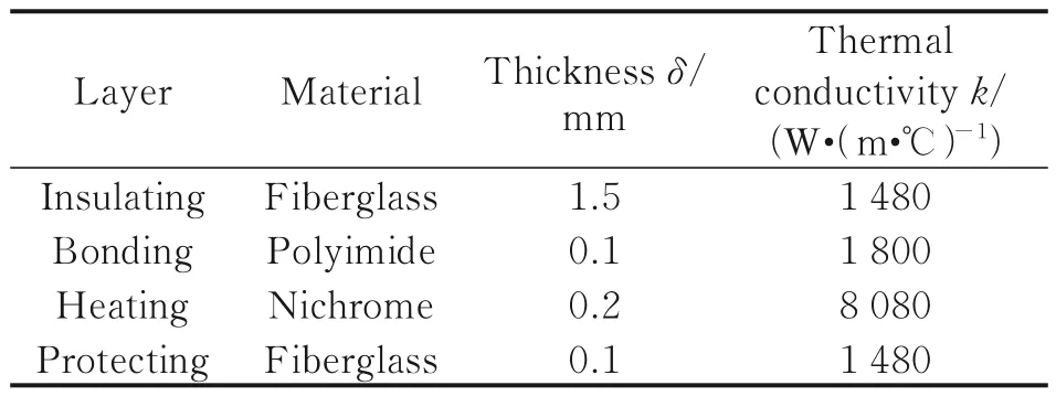
Table 1 Material parameters for multilayer structure

Fig.1 Fiberglass composite airfoil and its multilayer structure
1.2 Preparation of super-hydrophobic coating
For the current investigation,the super-hydrophobic coating is prepared by the spray method.The hydrophilic surface is the fiberglass composite airfoil itself.The coatings are prepared by combining epoxy resin(EP)with polytetrafluoroethylene(PTFE)particles.The details of the spray method can be seen in our previous work[24-25].Firstly,EP is dissolved in ethyl acetate at a 1∶1 ratio to obtain EP solution.PTFE micro-particles(1—3 μm)are suspended in ethyl alcohol at a 1∶3 ratio under magnetic stirring for 10 min to obtain PTFE solution.The PTFE/EP suspension is obtained by mixing EP solution and PTFE solution at the ratio of 3∶16 under magnetic stirring for 10 min,followed by dispersion using an ultrasonic cell crusher for 3 min.Secondly,the curing agent D230 is added,and the resulting mixture is stirred for 10 min to obtain the crosslinkable composite coating.Before coating application,a layer of EP is sprayed on a composite airfoil,which acts as an adhesive.Then the coating is sprayed in multiple layers.Finally,the coating is cured in an oven at 100 ℃ for 3 h.The microstructure of coating is observed through scanning electron microscopy,as shown in Fig.2(a).The honeycomb structure with rough porous traps more air pockets,which facilitates the wettability of Cassie-Baxter and enhances hydrophobicity[26].The wettability of the super-hydrophobic coating and fiberglass composite is tested at room temperature,as shown in Fig.2(b).
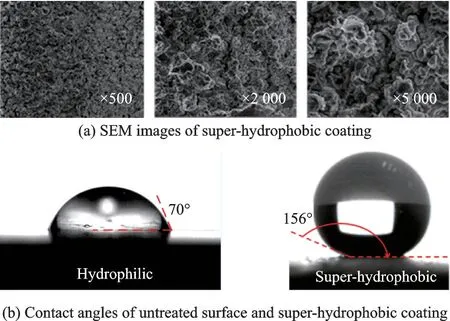
Fig.2 Microstructure and hydrophobicity characterization of super-hydrophobic coating
1.3 Experimental setup
All of the following experiments are conducted in a closed ice wind tunnel.The details of the test section can be seen in our previous work[27-28].Fig.3(a)shows the experimental setup in this study.A digital camera(30 frame/s)is used to capture the ice formation and ice shedding on the upper surface of airfoils.An infrared camera(100 frame/s)is applied to measure the temperature distribution through a rectangular slit.The infrared camera has a limited viewing range,thus 10 typeKthermocouples with a precision of ±0.1 ℃ are located on the upper surface to measure temperature distribution.Based on surface temperature,using the proportional integral derivative(PID)method,power supplies adjust the heating power of electro-thermal films.A power analyzer is used to record the input power of the electro-thermal films.
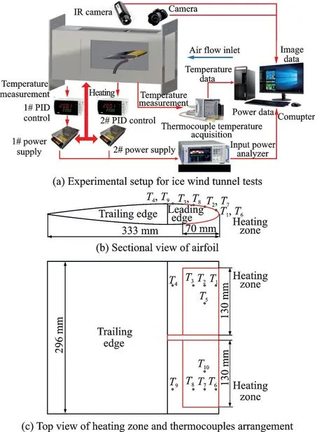
Fig.3 Schematic diagram for ice wind tunnel tests and heating zone/thermocouples arrangement
The airfoil has a chord length of 333 mm and a wingspan length of 296 mm,as shown in Figs.3(b,c).The super-hydrophobic coating covers the leading edge of the airfoil(30% of the chord length).The areas enclosed by the red dotted line are the heating zone,which has a projected size of 70 mm chordwise(21% of the chord length)and 130 mm spanwise,covering the impact zone of water droplets.The heating zones are arranged symmetrically along the central axis of the airfoil.A narrow electrothermal film is attached to the outer surface of the airfoil at the center line to separate the accreted ice.Fig.3(c)illustrates the layout of thermocouples.In order to maintain high flatness and high hydrophobicity of the coating,the holes(0.6 mm)are designed in the spacing between the heater wires.The thermocouples are perforated from the inside through holes and fixed to the skin surface by heatconductive silica gel.Here,the measurement pointsT1andT6are arranged inside the impact zone.T4andT9are in the runback zone.The other six thermocouples are arranged inside the heating zone but outside the impact zone.The thermocouplesT5andT10convert temperatures into electrical signals that control the heating power.
1.4 Experimental conditions
The icing conditions of all the experiments are the same:median volumetric diameter(MVD)of 51.8 μm,liquid water content(LWC)of 0.8air temperature(Ta)of -5 ℃,airspeed(Va)of 50 m/s and angle of attack(AOA)of 0°.In order to validate the performance of the hybrid anti-/de-icing strategy,icing tests,anti-icing tests,and de-icing tests are carried out,respectively,as shown in Table 2.

Table 2 Experimental conditions
For the convenience of description,in the paper,the super-hydrophobic coating airfoil without heating is named SHS,and the untreated airfoil without heating is named FG.The fiberglass composite airfoil has super-hydrophobic coating and embedded electro-thermal film(SHS-EET).The untreated fiberglass composite airfoil has an embedded electro-thermal film(FG-EET).The untreated fiberglass airfoil has underground electro-thermal film(FG-UET).
2 Results and Discussion
2.1 Anti-icing performance of super-hydrophobic coating
Fig.4 shows the icing process of the super-hydrophobic coating(SHS)and untreated fiberglass composite(FG)in the first 120 s.The icing test is carried out without a heat source,except for the electro-thermal film at the center line.Since the glaze ice is transparent,it is difficult to distinguish the icing process on the surface of the fiberglass airfoil,as shown in Fig.4(a).The impinging droplets release latent heat and flow downstream,thus the temperature of flowing water film/rivulet is higher than that of the airfoil surface[29].The infrared camera distinguishes the icing beginning time and its extent evolution by observing the surface temperature.The results show that after water spray for 15 s,the ice accumulates obviously on the leading edge.With the water spray,the accreted ice extends to the trailing edge,as shown in Fig.4(b).There is no significant difference in terms of the icing range between the super-hydrophobic coating and untreated surface.The results indicate that super-hydrophobic coating has no contribution to ice protection when no heat source is applied,which agrees with that in Ref.[4].That is because the hydrophobic properties deteriorate in low-temperature and high-humidity conditions[30-31].Meanwhile,the volume of supercooled water droplets entrained in the airflow is small,which is easy to get stuck in the microstructure of the super-hydrophobic coating.Once the wettability of the super-hydrophobic coating changes to the Wenzel state,subsequent impinging supercooled water droplets form water film and freeze,resulting in a failure of the super-hydrophobic coating.The improvement of the durability of the super-hydrophobic coating,especially in low temperature and high humidity environments,is one of the most important works in the future.
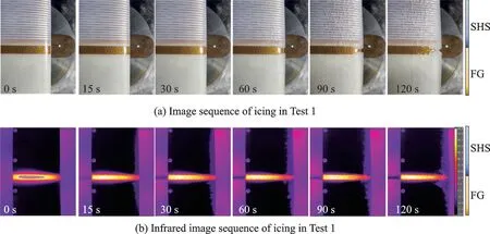
Fig.4 CCD image and infrared image sequences of icing in Test 1
The airfoil with accreted ice is cooled in a cold refrigerator to measure the ice thickness by a 3-D scanner(highest resolution 10 μm).Figs.5(a,b)show the airfoil before and after the icing test,respectively.The accreted ice is thicker near the central line due to the runback water to the sides.The regions,20—50 mm spanwise away from the center line,are selected for comparison,as shown in Fig.5(c).The results show that the icing range and icing shape are similar for SHS and FG.Although the thickness of accreted ice on the SHS surface is smaller than that of the untreated surface,as shown in Fig.5(d),the super-hydrophobic coating has a disappointing performance in anti-icing.However,a dry super-hydrophobic coating with the help of a heat source could effectively improve the ability of anti-icing performance[32].
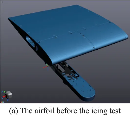

Fig.5 Comparison of ice shape for FG and SHS
2.2 De-icing performance of hybrid strategy
The multiple cross-sections are intercepted to eliminate the effect of the non-uniformity of accreted ice.The maximum thickness difference of accreted ice at stagnation points for SHS and FG is 1.16 mm and 0.465 mm,respectively.The thickness error of accreted ice has no effect on the evaluation of the anti-icing performance of the super-hydrophobic coating in this paper.
The available energy for icing protection of UAVs is inadequate,so the non-critical components usually adopt de-icing strategies.The ice shedding timetshis an essential parameter to evaluate the performance of de-icing strategies.Both the thermal resistance and surface wettability affect the ice shedding time and energy consumption.Fig.6 shows the de-icing process of FG-EET and FG-UET airfoils.The results show that despite the electro-thermal films being turned on simultaneously,the surface temperature of FG-EET airfoil rises faster.This is because the lower thermal resistanceRT,which is defined as
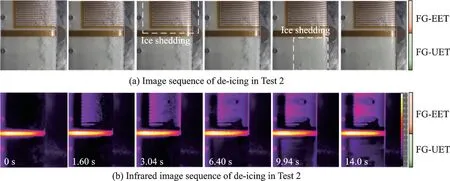
Fig.6 CCD image and infrared image sequences of de-icing in Test 2
whereδiis the thickness of theith layer andkithe thermal conductivity of the corresponding material.According to the parameters in Table 1,the thermal resistance of the integral structure is 95% lower than that of the structure of FG-UET.As a result,the FG-EET has a higher conversion efficiency from electrical energy to heat and faster thermal conduction.As the surface temperature continues to rise,the interface ice between the accreted ice and the airfoil melts.Then,the bulk of ice on the FGEET sheds off at 3.04 s under the action of airflow.However,the accreted ice on the FG-UET shed at 9.94 s.As a result,the integrated airfoil FG-EET is 69.4% more efficient in terms of de-icing period.
The PID method controls the heating powers of electro-thermal films to reach the target temperature(1 ℃)during the de-icing period,as shown in Fig.7.Before the heating,the interface between accreted ice and airfoil at positions 1# and 6# is a mixture of ice and water,because temperatures equal to 0 ℃.Fig.7(a)shows that as the electro-thermal film works,the surface temperatures(T2,T3)in heated zone evolution rise rapidly.When the thermocoupleT5approaches the target temperature,the heating power decreases,but the surface temperature continues to rise until the accreted ice sheds.In contrast,the surface temperature of FG-UET rises slowly.Fig.7(b)suggests that with the electro-thermal film working,the thermocouples temperaturesT6andT7gradually rise and exceed 0 ℃.This is because the accreted ice fails to shed and acts as insulation,avoiding the forced convection heat transfer between the thermocouples and cold airflow.Then,the thermocoupleT10takes a long time to reach the target temperature,causing the heating power to decrease to 0.In Test 2,the energy consumption of FG-EET is 615.82 J,and that of FG-UET is 1 528.75 J.As a result,the integrated airfoil is 59.72% more efficient in terms of energy consumption.Unfortunately,the ice melts and forms runback water,which freezes outside of the heated area during the de-icing process.The super-hydrophobic coating helps to shed runback water,avoiding icing in the unprotected zone.

Fig.7 Temperature profile and input heat flux density evolution in Test 2
Fig.8 shows the de-icing process for SHS-EET and FG-UET.The results show that the bulk of ice on the SHS-EET sheds at 3.68 s,which no residual ice in the heated region.However,the accreted ice on the FG-UET melts first,producing a large amount of runback water.Then,the ice sheds at 10.4 s,which is similar to thetshof Test 2.Thus,the de-icing performance is reproducible and the error in the shedding time is acceptable given the difference in the accreted ice shape in the ice wind tunnel.As a result,the SHS-EET is 64.6% more efficient in terms of de-icing period.

Fig.8 CCD image and infrared image sequences of de-icing in Test 3
Fig.9 shows the evolutions of surface temperatures and input heat flux density during the de-icing process for the SHS-EET and FG-UET.When the electro-thermal film works,the heating power of SHS-EET rapidly increases to 160 W and maintains a period,leading to a fast surface heating,as shown in Fig.9(a).The thermocouple temperaturesT2rise to 0 ℃ at 3.68 s and the accreted ice sheds off.Fig.9(b)shows that the de-icing period(tsh=10.4 s)is close to the result of Test 2.In Test 3,the energy consumption of SHS-EET is 486.71 J,and that of FG-UET is 1 758.01 J.As a result,the SHS-EET is 72.3% more efficient in terms of energy consumption.
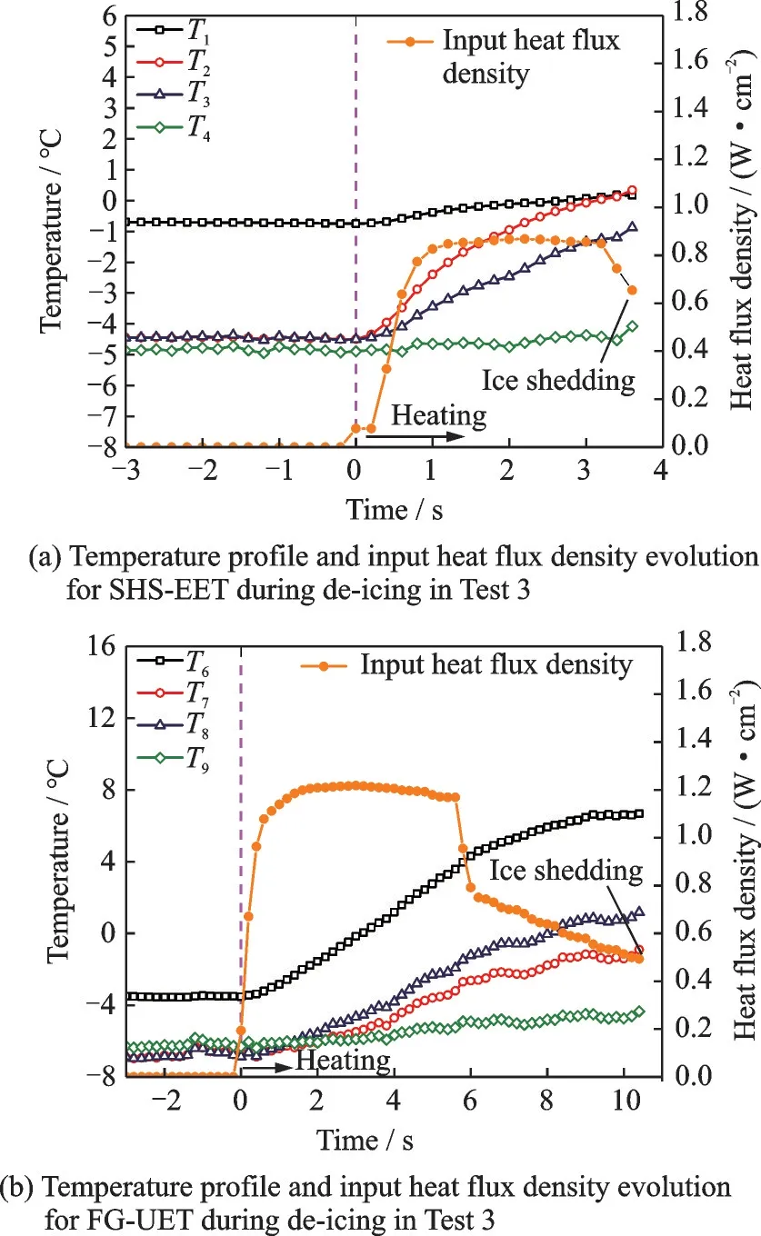
Fig.9 Temperature profile and input heat flux density evolution with time during de-icing Test 3
The increase in efficiency is due to three reasons:(1)Despite the icing range being similar,the less amount of accreted ice on super-hydrophobic coating;(2)the microstructure and hydrophobicity are beneficial to shed off the water,which is melted from the interface ice layer;(3)the integral structure strategy reduces the thermal resistance and enhances heat conduction.
2.3 Anti-icing performance of hybrid strategy
To avoid the icing of runback water,the traditional dry anti-icing method requires a high surface temperature,which results in a huge energy consumption.The anti-icing surface temperature(Tanti)is another critical parameter to evaluate the performance of the icing protection strategy.Before the water spray,the surfaces are separately heated to the target temperatures,which are confirmed by pretests.In pre-tests,the surface temperature is reduced gradually until the airfoil appears accreted ice in the heated area.In Test 4,the anti-icing surface temperature and energy consumption are analyzed.
Fig.10 shows the evolutions of surface temperatures and input heat flux density before the water spray.Because of the advantage of integral structure,the surface temperature of SHS-EET rises faster.During the initial heating phase,the temperature rapidly approaches the target value.Under the action of cold airflow and heating film,the input power changes continuously to maintain the target temperature,as shown in Fig.10(a).The results illustrate the rapid response of temperature on SHS-EET to power variations.Position 2#,located in the heated zone and parallel to position 5#,is used as a reference.The temperatureT2maintains 9 ℃±2 ℃ for subsequent anti-icing Test 4.Fig.10(b)suggests that the surface temperature response of FG-UET is slower because the temperature fails to be stable even in 70 s.Besides,the FGUET needs a higher surface temperatureTanti=20 ℃for anti-icing Test 4.Thus,the strategy of the integral airfoil with PID heating law has three advantages over constant heat flux density:(1)The maximum heat flux at the initial stage realizes the rapid heating;(2)the heat flux decreases when approaching the target temperature to avoid overheating;(3)the surface temperature keeps stable at the target value by automatically changing the heat flux regardless of the external environment changes.
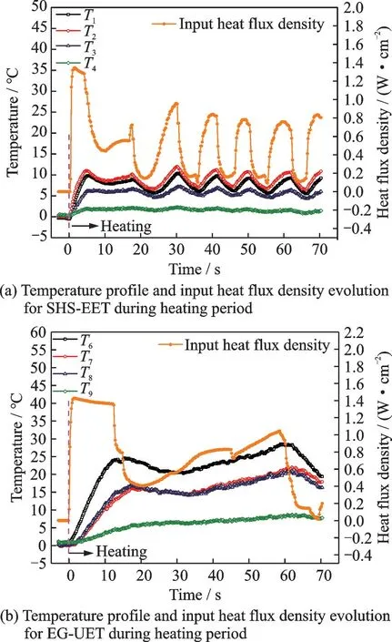
Fig.10 Temperature profile and heat flux density evolution during heating period
Fig.11 shows the anti-icing process for SHSEET and FG-UET.The results show that two sides of the airfoil successively avoid the accreted ice in the heated zone during the test period 120 s.In addition,there is no runback water icing on the super-hydrophobic coating.In contrast,for the wet anti-icing strategy,the runback water on FG-UET appears and freezes outside the protection area.Therefore,the super-hydrophobic coating achieves dry anti-icing at a relatively low temperature,which provides the possibility of an anti-icing strategy for UAVs.

Fig.11 CCD image and infrared image sequences of anti-icing in Test 4
Fig.12 shows the evolutions of surface temperatures and input heat flux density during the anti-icing process.The results show that the heating power increases after encountering water spray.This is because the water droplets impinging on the surface take away heat,leading to a decrease in the surface temperature.The PID controls input power to maintain the anti-icing temperature.Besides,the results suggest that despite both sides of airfoils achieve the anti-icing,the surface temperature of SHS-EET is lower than that of FG-UET.This is because the super-hydrophobic coating remains dry during the antiicing test.The impinging supercooled water droplets splash or rebound,reducing contact time and nucleation rate,thus avoiding the formation of accreted ice.In Test 4,the energy consumption of SHS-EET is 18 196.01 J,and that of FG-UET is 24 655.04 J.Thus,the SHS-EET strategy is 26.2% more efficient in terms of energy consumption.The increase in efficiency is due to two reasons:(1)Low anti-icing temperature for the superhydrophobic coating;(2)low thermal resistance for the integral structure.Considering the severe runback water icing on the FG-UET,it is necessary to continue to raise the surface temperature to achieve dry anti-icing.In this study,however,the power supply is insufficient for a dry anti-icing test in an ice wind tunnel environment.Therefore,the SHSEET has greater advantages in terms of anti-icing temperature and energy consumption.
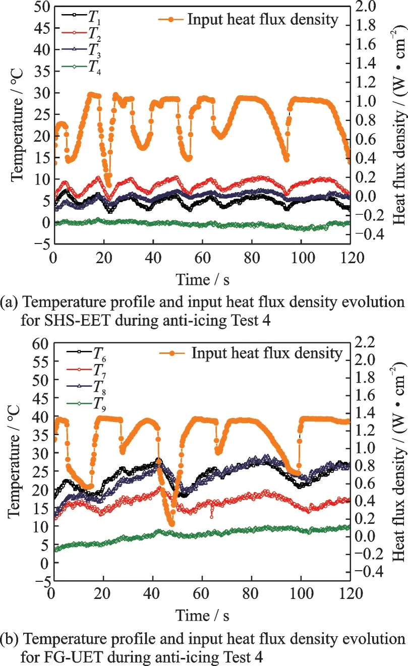
Fig.12 Temperature profile and heat flux density evolution during anti-icing Test 4
3 Conclusions
The de-/anti-icing strategy suitable for the icing protection system of UAVs is urgently required.Considering the extensive application of composite material,the de-/anti-icing strategy based on fiberglass composite is studied.The electro-thermal film is embedded into the composite laminates to reduce thermal resistance.The super-hydrophobic coating is sprayed on the skin to prevent the runback water from freezing.The results of tests in an ice wind tunnel show that the super-hydrophobic coating fails to achieve anti-icing in the absence of a heat source.Besides,using the PID method,the ice-shedding period of the integral airfoil with embedded electrothermal film and external super-hydrophobic coating is reduced by 64.6% and the energy consumption is reduced by 59.7%.Moreover,the super-hydrophobic coating helps the integral airfoil achieve dry antiicing at a relatively low temperature(Tanti=10 ℃),leading to a 26.2% decrease in energy consumption compared with the traditional wet anti-icing strategy.The super-hydrophobic/electro-thermal synergistically anti-icing/de-icing strategy provides a reference for the design of UAVs de-/anti-icing systems.
杂志排行

Transactions of Nanjing University of Aeronautics and Astronautics的其它文章
- Anti-icing Skin with Micro-nano Structure Inspired byFargesia Qinlingensis
- Evaluation of Different Cloud Microphysics Schemes on the Meteorological Condition Prediction of Aircraft Icing
- Photothermal Anti/De-icing Performances of Superhydrophobic Surfaces with Various Micropatterns
- Mesh Impact Analysis of Eulerian Method for Droplet Impingement Characteristics Under Aircraft Icing Conditions
- Design Principle of Mixed-Wettability Surfaces for Inducing Droplet Directional Rebound
- Analysis of Ice-Shaped Surface Roughness Based on Fractal Theory