HUID:DBN-Based Fingerprint Localization and Tracking System with Hybrid UWB and IMU
2023-03-12JunchangSunRongyanGuShiyinLiShuaiMaHongmeiWangZongyanLiWeizhouFeng
Junchang Sun,Rongyan Gu,Shiyin Li,*,Shuai Ma,Hongmei Wang,Zongyan Li,Weizhou Feng
1 School of Information and Control Engineering,China University of Mining and Technology,Xuzhou 221116,China
2 Peng Cheng Laboratory,Shenzhen 518055,China
3 School of Information and Communications Engineering,University of Electronic Science and Technology of China,Chengdu 611731,China
Abstract: High-precision localization technology is attracting widespread attention in harsh indoor environments.In this paper,we present a fingerprint localization and tracking system to estimate the locations of the tag based on a deep belief network(DBN).In this system,we propose using coefficients as fingerprints to combine the ultra-wideband (UWB) and inertial measurement unit (IMU) estimation linearly,termed as a HUID system.In particular,the fingerprints are trained by a DBN and estimated by a radial basis function(RBF).However,UWB-based estimation via a trilateral method is severely affected by the non-line-ofsight (NLoS) problem,which limits the localization precision.To tackle this problem,we adopt the random forest classifier to identify line-of-sight(LoS)and NLoS conditions.Then,we adopt the random forest regressor to mitigate ranging errors based on the identification results for improving UWB localization precision.The experimental results show that the mean square error (MSE) of the localization error for the proposed HUID system reduces by 12.96%,50.16%,and 64.92% compared with that of the existing extended Kalman filter (EKF),single UWB,and single IMU estimation methods,respectively.
Keywordst:Ultra-wideband(UWB);inertial measurement unit(IMU);fingerprints positioning;NLoS identification;estimated errors mitigation;deep belief network(DBN);radial basis function(RBF)
I.INTRODUCTION
With the development of wireless communication technology in recent years,accurate and low-cost localization techniques can be achieved.The Global Positioning System (GPS) and the BeiDou Navigation Satellite System(BDS)have been widely used for navigating outdoor environments,which have become part of daily life.However,the GPS and BDS often provide weak signals or are unavailable for indoor localization [1—3],which inspires us to explore indoor positioning methods.
Conventional Wi-Fi based positioning method has been explored in the indoor environment.For example,authors in [4] use a novel metasurface to control the reflected signals for reconfigurable radio environment,the results show the centimeter-level positioning error can be achieved based on the received signal strength.As for the penetrability,the large bandwidth ultra-wideband(UWB)signals have excellent performance,which can easily penetrate walls and partitions to achieve high positioning accuracy[5].Recent works have investigated applications of the UWB-based localization technology in harsh indoor environments.In [6],an adapted error map positioning method is proposed by using particle filter,which is proved to improve the accuracy based on the measurement data.In [7],the robot location is estimated by using the proposed mixture Monte-Carlo localization method based on UWB sensors.In [8],the positioning system exploits non-coherent angular measurements based on the single anchor to estimate locations.Moreover,the locations of the tag are estimated by comparing the least squares (LS) estimator,the extended Kalman filter (EKF),and the particle filter based on the round-trip time-of-flight(RToF)method in[9].However,these positioning and tracking methods suffer from the interference of reflection,refraction,and obstructions due to the non-line-ofsight (NLoS) condition.Therefore,it is necessary to identify the line-of-sight (LoS) and NLoS conditions and mitigate ranging errors to improve localization precision.
In previous works,the NLoS identification and mitigation methods are based on the ranging estimation[10—12],and power characteristics of the received signal [13—15].However,these methods are sensitive and low-efficient for the mobile tag tracking in the harsh indoor environment.Moreover,the NLoS condition is identified by using the error estimation model[16—18].However,these models are effectively established based on a special priori knowledge of the distribution function,which limits the application and extension in different scenarios.Subsequently,machine learning-based methods are investigated to identify the LoS and NLoS conditions,e.g.,the support vector machine (SVM) method [19—22],the random forest method [22—24],the convolutional neural network(CNN)method[25,26],and some other machine learning methods [22,27,28].Inspired by these,we adopt a random forest classifier to identify the LoS and NLoS conditions,and adopt a random forest regressor to mitigate the ranging error based on the identification result.
After NLoS identification and ranging error mitigation,the locations of the tag can be estimated with the trilateral method.To further improve the localization accuracy,a combination of UWB and inertial measurement units(IMU)localization system is investigated.In [29],a tightly coupled sensor fusion approach is utilized to combine the measurement information of UWB and IMU.The result shows the accurate location and orientation estimation compared to an independent system.In [30],a real-time localization and tracking algorithm in combination of UWB and IMU based on the robust sensor fusion is proposed,with the result showing the precise velocity and height estimation.An EKF and an unscented Kalman filter (UKF) are utilized to integrate UWB and IMU for positioning [31].The experimental result shows the high-accuracy in Internet of Things (IoT) environments.The UWB and IMU are combined with a biomechanical model to track localization and posture based on the proposed motion capture algorithm[32].
To this end,we aim to take advantages of complementary characteristics of UWB and IMU for improving indoor localization accuracy.In particular,on the one hand,the localization accuracy of the UWB estimation is further improved by IMU;on the other hand,the long-term drift error of IMU is calibrated by UWB.Therefore,in this paper,we propose a novel fingerprint localization system with hybrid UWB and IMU estimation based on a deep belief network(DBN),termed as HUID system.In UWB ranging,we adopt a random forest classifier to identify the LoS and NLoS conditions.To reduce the effect on ranging in the NLoS condition,we adopt a random forest regressor to mitigate the ranging error.Then,we propose a fingerprint localization system that use coefficients as fingerprints to combine UWB and IMU estimation locations linearly.Specially,the determination of the fingerprints is given by a DBN,which is divided into an offline training phase and an online localization phase.In the training phase,we propose to calculate coefficients via a minimization of the Euclidean distance of real and estimated localization coordinates.Then,we train fingerprints via optimizing weights and bias of the DBN structure based on the amplitude of normalized received signals [33].In the localization phase,we propose to use a radial basis function (RBF) to estimate fingerprints based on the trained DBN structure.Consequently,we can estimate the localization and tracking of the tag.The key contributions of our approach are outlined as follows.
・ In the HUID system,we propose to use coefficients calculated via a minimization of the Euclidean distance of real location coordinates and estimated hybrid location coordinates,to represent fingerprints for combining UWB and IMU estimations linearly.
・ The fingerprints are trained by a DBN,which consists of a stack of restricted Boltzmann machines(RBMs)and a back propagation(BP)neural network.In particular,we use the amplitude of normalized received signals as the input data of the DBN.Moreover,the fingerprints are estimated by a RBF with a Gaussian kennel function.
・ Based on the identification results of the random forest classifier,we adopt a random forest regressor to mitigate ranging errors and improve the precision of UWB-based location estimations.Finally,all the measurement data are available to be downloaded athttps://github.com/sunjc-cumt/indoor-positioning-data.
The rest of this paper is organized as follows.In Section II,the system model is described.In Section III,the UWB-based localization is presented,together with the NLoS identification and errors mitigation are investigated.The IMU-based localization method is given in Section IV.In Section V,the proposed HUID system is investigated with DBN and RBF.In Section VI,the experimental results are analyzed to demonstrate the effectiveness of the proposed HUID system.Finally,Section VII provides conclusions of the paper.
Notations:The notationsa,a,A,andAdenote scalar,vector,matrix,and set,respectively.ATdenotes the transpose.||·||2denotes theℓ2-norm.Pr(·|·)denotes the conditional probability distribution.Uandrandndenote uniform distribution and standard Gaussian distribution function,respectively.1N1×N2∈RN1×N2denotes aN1byN2matrix with all elements being 1.N{1,2,···,N},Nb{1,2,···,Nb},andNT{1,2,···,NT}.sigmoid(x)=
II.OVERALL SYSTEM MODEL
The proposed HUID is a DBN-based fingerprints localization system,which consists of the UWB system and the IMU system.The system is shown in Figure 1.
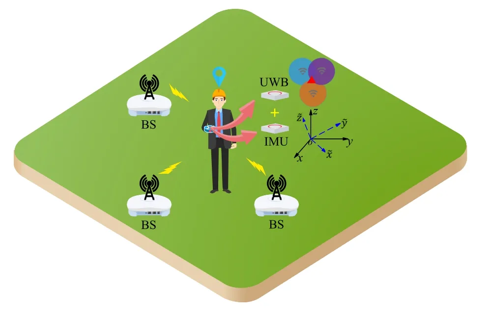
Figure 1.Illustration of the system.
For UWB-based localization,givenNbstationary base stations (BSs) with known coordinates pj=[px,j,py,j]T,j ∈Nb,and a tag with unknown coordinate un=[ux,n,uy,n]T,n ∈Nat then-th point,whereNdenotes the number of points in the measurement scenario.The locations of tag are obtained with estimated ranges from theNbBSs based on the trilateral localization method.However,the localization of UWB is severely affected by NLoS conditions,so the NLoS identification and ranging errors mitigation method is adopted to improve precision.The estimated location coordinates are marked as,n ∈N.
For IMU-based localization,the locations of IMU are estimated with acceleration and angular velocity values while the IMU device is attached to the tag.Then,the coordinates are transformed from device coordinate systemsto earth coordinate systemsxoy.The estimated location coordinates are marked as,n ∈N.Moreover,the initial location of the IMU is given by UWB estimation (only the 2-D coordinate system is adopted,i.e.,the estimatedz-axis coordinate of the IMU is not considered).Therefore,the estimation of IMU and UWB are assumed to be strongly related.
To take advantages of complementary characteristics of UWB and IMU,we present a DBN-based fingerprints localization system to improve localization precision,termed as HUID system.The system consists of hybrid UWB and IMU estimation,which is given by
whereαn ∈R andβn ∈R denote the coefficients of the UWB and IMU systems,respectively,which are used as fingerprints in the HUID system.Therefore,the UWB-based localization estimation,IMU-based localization estimation,and fingerprints establishment are three important parts of the proposed HUID system.First,we present the UWB and IMU localization systems in detail.Then,the DBN-based fingerprints establishment is presented based on the UWB and IMU estimation.
III.UWB-BASED LOCALIZATION SYSTEM
UWB signals have a large bandwidth and perform well in the field of indoor localization,given their penetrability.Based on the RToF measurement method[34],the estimated distance between the tag and thej-th BS at then-th point is denoted by,j ∈Nb,n ∈N.Therefore,the estimated location coordinates of thenth point can be calculated by solving
The above optimization problem can be solved by using the LS method.
However,the location estimation suffers from the NLoS condition in harsh indoor environments,which limits the localization precision.Therefore,it is necessary to mitigate estimated errors in the NLoS condition for the UWB system.First,the NLoS condition can be identified according to the characteristics of normalized received signals.Then,based on the identification results,the errors are mitigated to improve precision.
3.1 NLoS Identification
The NLoS condition is identified using a random forest classifier,based on the characteristics of normalized received signals.These characteristics include variance,mean excess delay,root mean square(RMS)delay spread,and kurtosis of the normalized received signals[19,28].
The structure of the random forest classifier is shown in Figure 2,which consists of multiple decision trees of classification and regression trees (CARTs).First,we present the splitting criterion of tree nodes to generate the tree structure.Then,the structure of the random forest classifier can be generated based on a number of trees.Finally,the classification results are obtained based on the voting of each decision tree.
Due to the similarity of the splitting criterion for each node in a decision tree,let us take the first node splitting as an example.In the training datasetD{(Φj,n,zj,n),j ∈Nb,n ∈N},where Φj,nandzj,n ∈{−1,1}denote the selected characteristics and labels of thej-th BS at then-th point,respectively.In particular,zj,n=1 represents the LoS condition,andzj,n=−1 represents the NLoS condition.The Gini index before splitting is given by
where Pr(zj,n=−1) denotes the probability of the NLoS condition.Then,we assume theDis split intowithL1groups of data andD2ξwithL2groups of data based on the featureξ,whereξ ∈Φj,n.The Gini index after splitting is given by
The Gini index gain with the split feature ofξis given by
Finally,the Gini index gain is used to determine the splitting criterion of each node.
The generation of the random forest classifier is outlined in Algorithm 1.First,we randomly select a set of data from a given datasetD,sampling with replacement,which is marked as the sampling set.Then,we randomly select several features from the total characteristics to train decision trees,sampling without replacement,which is marked as the subset.The process of training decision trees is detailed in Algorithm 2.Finally,we can obtain multiple trees to generate the random forest classifier structure.
The generation of a decision tree is outlined in Algorithm 2.For each node in the tree,first,we calculate the Gini index for a given subsetThen,we calculate the Gini index gain after splitting based on each feature and select the largest value and corresponding feature to split node.Based on the above split process,we split each node of each layer in the tree until the stop conditions are satisfied.Therefore,the decision tree model is generated.
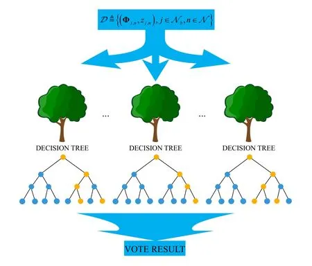
Figure 2.The structure of random forest classifier model.
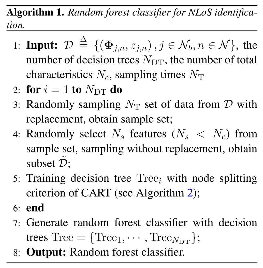
Algorithm 1.Random forest classifier for NLoS identification.1: Input: D∆={(Φj,n,zj,n),j ∈Nb,n ∈N},the number of decision trees NDT,the number of total characteristics Nc,sampling times NT 2: for i=1 to NDT do 3: Randomly sampling NT set of data from D with replacement,obtain sample set;4: Randomly select Ns features (Ns < Nc) from sample set,sampling without replacement,obtain subset ˜D;5: Training decision tree Treei with node splitting criterion of CART(see Algorithm 2);6: end 7: Generate random forest classifier with decision trees Tree={Tree1,···,TreeNDT};8: Output: Random forest classifier.
Finally,we can identify the NLoS condition with the characteristics of normalized received signals,based on the structure of the random forest classifier.
3.2 Estimated Error Mitigation
Based on the results of the identification,we adopt a random forest regressor to mitigate ranging errors for the NLoS condition.The regression training datasetA{(Φj,n,εj,n),j ∈Nb,n ∈N} is used to train the random forest regression model,whereεj,ndenotes the ranging error between thej-th BS and the tag at then-th point,which is given by
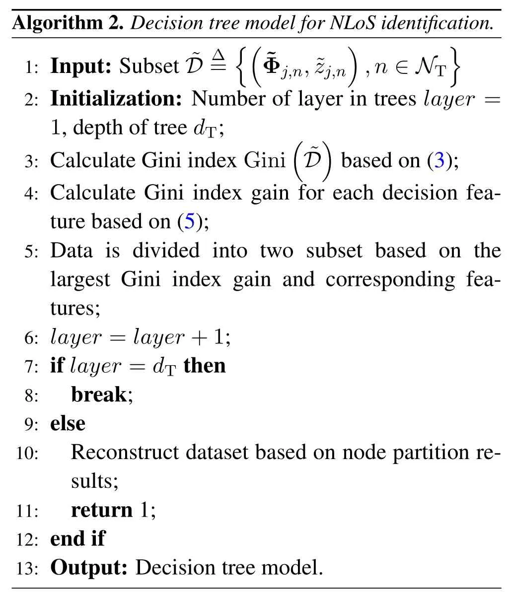
Algorithm 2.Decision tree model for NLoS identification.1: Input: Subset ˜D∆=images/BZ_153_1728_395_1759_441.png(˜Φj,n,˜zj,n)images/BZ_153_2159_395_2190_441.png,n ∈NT 2: Initialization: Number of layer in trees layer=1,depth of tree dT;3: Calculate Gini index Gini(˜D)based on(3);4: Calculate Gini index gain for each decision feature based on(5);5: Data is divided into two subset based on the largest Gini index gain and corresponding features;6: layer=layer+1;7: if layer=dT then 8: break;9: else 10: Reconstruct dataset based on node partition results;11: return 1;12: end if 13: Output: Decision tree model.
wheredj,ndenotes the real distance between thej-th BS and the tag at then-th point.
The CARTs are also used for random forest regression,while the node splitting criterion of the Gini index gain is replaced by mean square error (MSE).In detail,for each node,we assume an input datasetAis split intoAζ1andAζ2based on the featureζ,whereζ ∈Φj,n,which is given by
wheref1=f2=c1andc2are variances ofεi1,∀iandεi2,∀i,respectively.In each decision tree,we assume that the datasetAis split intoGsubsets after generating the regressor model based on the above node splitting criterion,i.e.,each subset cannot be split any further.Therefore,the output of the random forest regressor of thej-th BS at then-th point is given by
whereAu,gwithSgroups of data denotes theg-th subset in theu-th tree,andUdenotes the number of trees in the random forest regressor.
According to the random forest regressor model and output errors,the modifeid estimation distancecan be given by
Therefore,the estimated Euclidean distance in (2) is redefined as,where=when the tag is located in the LoS conditions,and=when tag is located in the NLoS conditions.Therefore,the location estimation of the UWB system is given by
IV.IMU-BASED LOCALIZATION SYSTEM
An IMU device is adopted to determine the locations of the tag by using a three-axis accelerometer and a three-axis gyroscope.The orientation of the IMU device is obtained by measuring the elemental rotation angles yawφ,pitchθ,and rollϕ,which are defined as rotations about thez-axis,x-axis,andy-axis,respectively [35].Then,the rotation matrix R(φ,θ,ϕ)can be given by(11).
Therefore,coordinates can be transformed from device coordinate systems to reference coordinate systems(i.e.,earth coordinate systems),as given by
whereCanddenote reference coordinate systems and device coordinate systems,respectively.
Generally,normalized quaternion is introduced to replace the rotation matrix for reducing computational complexity,which is defined as
The state update of quaternion at then-th point is given by
where
∆tdenotesthesamplingperiod,andare three-axis gyroscope values at the(n −1)-th point in the device coordinate systems.
Therefore,the rotation matrix R(φ,θ,ϕ)can be expressed by quaternion[36],which is redefined as
Finally,the estimation location coordinates at thenthe point are given by
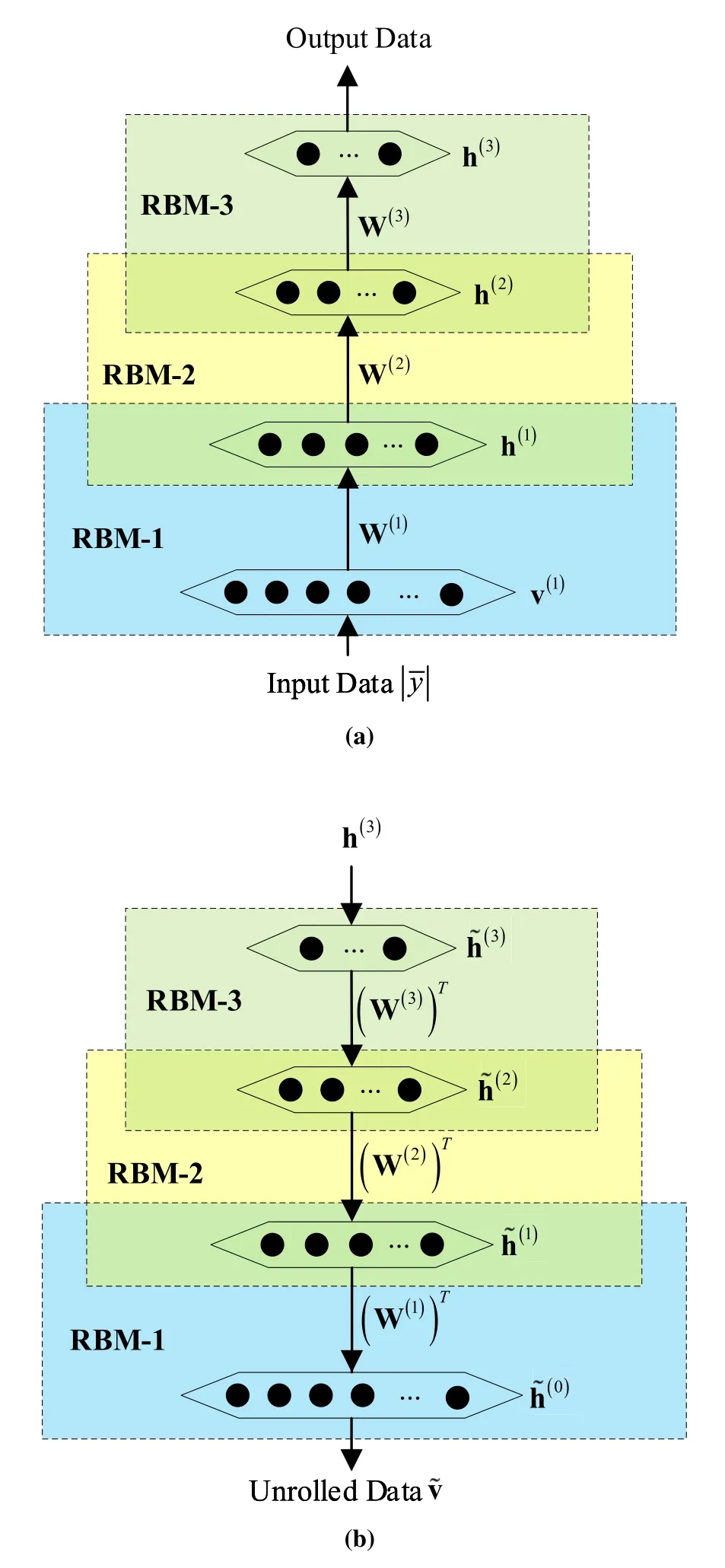
Figure 3.DBN structure with three restricted RBMs and a BP neural network.
where
V.HUID-BASED LOCALIZATION SYSTEM
According to(1),the fingerprints are established with a DBN based onin (10) andin (17).We present the fingerprints establishment process by using DBN training as follows.
The DBN[33,37]is adopted to train the fingerprintsαnandβn,which consists of an offline training phase and an online localization phase.In the offline training phase,the fingerprints{αn,n ∈N}and{βn,n ∈N}are calculated by
where undenotes real location at then-th point.
The structure of the DBN consists of three RBMs and a BP neural network,and contains three stages:pretraining,unrolling,and fine-tuning [38].In particular,each RBM is an undirected graphical model based on an energy function,which contains a layer of visible neurons and a layer of hidden neurons.It is worth pointing out that the output values of the previous layer RBM are used as the input of the next layer RBM.
Let v(k)=and h(k)=denote the visible layer vector and hidden layer vector of thek-th RBM,whereMkandNkare the number of neurons of the visible layer and hidden layer,respectively,with the superscriptk ∈{1,2,3}.To reduce the dimension of the training data,the number of neurons in the next hidden layer is less than previous hidden layer[33,38],i.e.,N1> N2>N3.Moreover,let a(k)=anddenote the bias of the visible layer v(k)and the hidden layer h(k),respectively.In addition,
is denoted as the connection weighting between the visible layer v(k)and the hidden layer h(k).
1)Pretraining:The structure of the pretraining stage of the DBN is shown in Figure 3a.The energy of thek-th RBM is given by
The joint probability distribution is an undirected graphical model,which is given by
To obtain the optimal parameters W(k),a(k),and b(k),the goal is to minimize the log cost function of thek-th RBM,which is given by
Equivalently,the problem can be transformed into
The partial derivations of the optimization function with respect to the parameters W(k),a(k),and b(k)are difficult and complicated when using the conventional gradient method [39].Generally,the contrastivedivergence-1(CD-1)algorithm is adopted to estimate partial derivations approximately by
where sigmod(·) denotes the activation function of RBM.Therefore,h(k)can be obtained fromby using the Gibbs sampling method.The Gibbs sampling is a conventional sampling method.The thresholds are given byηi ∼U(0,1),so
Then,the conditional probability distributioncan be given by
Finally,the updated parameters W(k),a(k),and b(k)are given by
whereγdenotes the learning rate.
2) Unrolling:After the pretraining process,the structure is unrolled to obtain unrolled input data ˜v.As shown in Figure 3b,the unrolling process is based on parameters W(k),b(k),and h(k),which are given by
wherek=3,2,1,and h˜(3)=h(3),b(i0)=a(i1).Therefore,the unrolled input data can be obtained by=.
3) Fine-tuning:In the fine-tuning stage,we update the weight matrix parameters and bias parameters of RBMs based on the error between the unrolled data and original data of thek-th layer with a BP neural network [40].Let parameterthe MSE of thekth layer can be written as
where Ξ(k−1)denotes the number of elements in the(k −1)-th layer,k=3,2,1,and h(0)is defined as the original data,i.e.,h(0)=||n.
Then,we adopt the gradient descent method to update parameter Θ,which is given by
where Υ denotes the learning rate.
The offline training phase of the DBN is given in Algorithm 3.First,the amplitudes of normalized received signals{||n,n ∈N} inNtraining locations are collected.For then-th training location,we collect: real location coordinates un,estimated location coordinatesbased on mitigated ranging from UWB measurement,and estimated location coordinatesbased on accelerometer and gyroscope information from an IMU device.Therefore,the estimated fingerprintsαnandβncan be calculated by using (20).Then,for the pretraining stage,the CD-1 method and the Gibbs sampling method are used to update the parameters W(k),a(k),and b(k)of thek-th RBM by using(32).Moreover,for the unrolling stage,the unrolled datacan be calculated based on the updated W(k)and b(k)by using the Gibbs sampling method.For the BP stage,we update parameters W(k)and b(k)by using the gradient descent method.Finally,the output datacan be obtained based on the trained DBN after the iteration is terminated.
4)Location Estimation of the Tag:In the online localization phase,for a tag with an unknown location,the output dataof the third layer of the RBM can be calculated by using (28) and the Gibbs sampling method based on the weight matrix {W∗n,n ∈N}and bias {b∗n,n ∈N}.
Moreover,the RBF of the Gaussian function is adopted,which is given by
whereσ2ndenotes the variance of h(Tag)n,andλdenotes the coefficient of variance.Therefore,the estimated fingerprintsandare given by
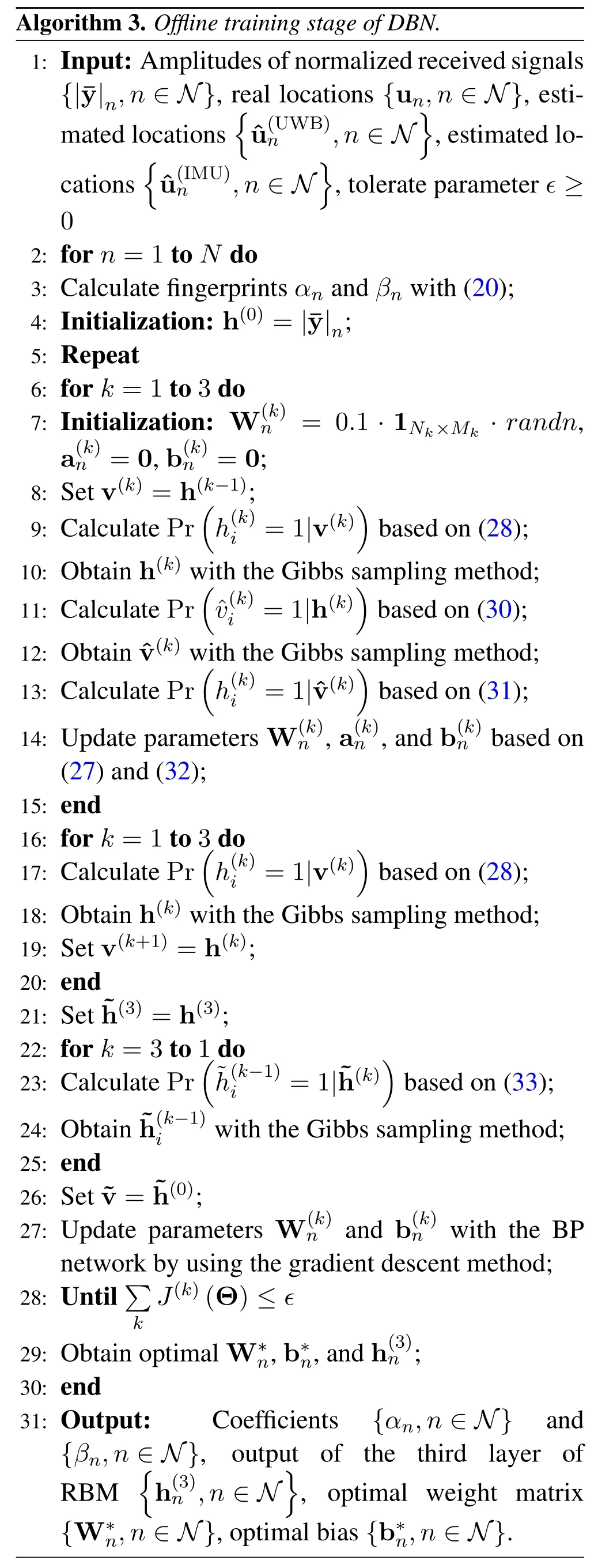
Algorithm 3.Offline training stage of DBN.1: Input:Amplitudes of normalized received signals{|¯y|n,n ∈N},real locations{un,n ∈N},estimated locations images/BZ_158_589_502_619_547.png u(UWB)n,n ∈N images/BZ_158_909_502_939_547.png,estimated locations images/BZ_158_431_588_462_634.png u(IMU)n,n ∈N images/BZ_158_736_588_766_634.png,tolerate parameter ϵ ≥0 2: for n=1 to N do 3: Calculate fingerprints αn and βn with(20);4: Initialization: h(0)=|¯y|n;5: Repeat 6: for k=1 to 3 do 7: Initialization: W(k)n=0.1 · 1Nk×Mk · randn,a(k)n=0,b(k)n=0;8: Set v(k)=h(k−1);9: Calculate Prh(k)(i=1|v(k))based on(28);10: Obtain h(k)with the Gibbs sampling method;11: Calculate Prv(k)(i=1|h(k))based on(30);12: Obtain v(k)with the Gibbs sampling method;13: Calculate Prh(k)(i=1|v(k))based on(31);14: Update parameters W(k)n,a(k)n,and b(k)n based on(27)and(32);15: end 16: for k=1 to 3 do 17: Calculate Prh(k)(i=1|v(k))based on(28);18: Obtain h(k)with the Gibbs sampling method;19: Set v(k+1)=h(k);20: end 21: Set ˜h(3)=h(3);22: for k=3 to 1 do 23: Calculate Pr(˜h(k−1)i=1|˜h(k))based on(33);24: Obtain ˜h(k−1)iwith the Gibbs sampling method;25: end 26: Set ˜v=˜h(0);27: Update parameters W(k)n and b(k)n with the BP network by using the gradient descent method;28: Untilimages/BZ_158_389_2568_401_2614.pngimages/BZ_158_401_2534_449_2580.png J(k)(Θ)≤ϵ 29: Obtain optimal W∗n,b∗n,and h(3)n ;30: end 31: Output:Coefficients {αn,n ∈N} and{βn,n ∈N},output of the third layer of RBM k images/BZ_158_423_2858_453_2903.png h(3)n,n ∈N images/BZ_158_676_2858_706_2903.png,optimal weight matrix {W∗n,n ∈N},optimal bias {b∗n,n ∈N}.
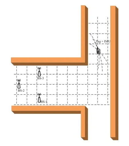
Figure 4.Measurement scenario.
Finally,the estimated location coordinatesof the tag in the HUID indoor localization system can be determined.
VI.EXPERIMENTAL RESULTS ANALYSIS
In our experiment,the devices PlusOn 440 and BWIMU50 are used for UWB-based location estimations and IMU-based location estimations,respectively.In particular,the PlusOn 440 includes three BSs with known locations placed at (0,0),(4,1.6),and (4,−2.4) in meters,and a tag with an unknown location is attached to the IMU,as shown in Figure 4.
6.1 NLoS Identification
We collect 230,000 group of received signals data when the tag is moved at each point under LoS and NLoS conditions at different sampling time.In particular,50%data are collected under the LoS condition,and 50%data are collected under the NLoS condition.For training the random forest classifier,we investigate the identification accuracy over the number of treesNDTand the depth of treesdTwith 10-fold cross validation,as shown in Figure 5.The result shows that the accuracy increases asNDTanddTincrease.Moreover,it can be observed that the the accuracy converges to a stable ratio of 0.98 whenNDT≥7 anddT=6.
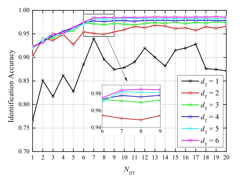
Figure 5.The variety of identification accuracy.
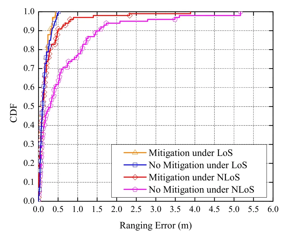
Figure 6.The CDF of ranging errors under LoS and NLoS conditions.
Based on the identification results,we can calculate ranging errors under the LoS and NLoS conditions,respectively.Then,we adopt the random forest regressor to mitigate ranging errors.The cumulative distribution function(CDF)of ranging errors,with mitigation and without mitigation under LoS and NLoS conditions,is given in Figure 6.For the LoS condition,we can observe that the 90%ranging errors with and without mitigation are all within 0.25 m.Meanwhile,the CDF of the ranging error with and without mitigation is almost coincident.Therefore,it is not necessary to mitigate ranging errors for the LoS condition.For the NLoS condition,the ranging errors are significantly reduced.In particular,the 90%errors are within 0.5 m after the random forest regression compared with 1.5 m for the original ranging errors.
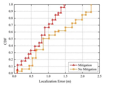
Figure 7.The CDF comparison of localization errors before and after mitigation under the NLoS condition.

Table 1.The MSE of localization errors in NLoS conditions with regression.
To clarify the impact of the ranging error mitigation on the localization accuracy,the CDF comparison of localization errors,with and without mitigation under the NLoS condition,is investigated in Figure 7.The results show that the localization errors significantly reduce after mitigation.In detail,at a CDF of 89%,the localization error is less than 1.2 m,compared with that of 2.0 m before mitigation.Numerically,the results of Table 1 show that the MSE of localization error with mitigation reduce by 51.71%compared with the MSE without mitigation.These experimental results show the effectiveness of the random forest regressor.
6.2 Proposed HUID Localization and Tracking Performance
To evaluate the performance of HUID system,we measure the accuracy of the localization and tracking by using the devices PlusOn 440 and BW-IMU50 in the scenario as shown in Figure 4.
1)HUID Localization and Tracking:The proposed HUID system consists of an offline training phase and an online localization phase.In the offline training phase,we train the DBN as shown in Algorithm 3 with a structure ofN1=200,N2=100,andN3=40.In the online localization phase,we calculate theand,and use the trained DBN and normalized received signals to estimate fingerprintsand.Therefore,the estimatedcan be obtained.
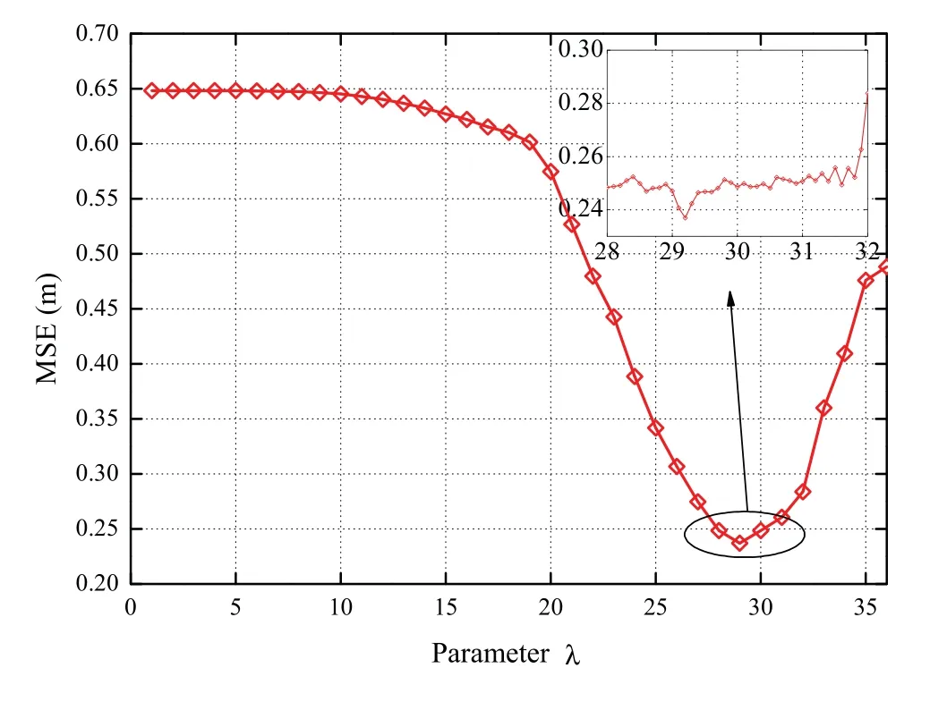
Figure 8.The influence of coefficient λ on localization errors.
Figure 8 investigates the influence of the coefficientλin (36) on localization errors estimation by using a Monte-Carlo method.The optimal point can be obtained sinceλ=29.2.After the determination of the coefficientλ,the indoor tracking paths can be described at an area of 10 m×13 m,as shown in Figure 9.The BS-1,BS-2,and BS-3 represent three BSs.The gray region represents the wall.The yellowdotted region represents that there is no obstruction between the mobile tag and three BSs,which is denoted as the LoS region.Similarly,the green-dotted region represents that there is wall shelter between the mobile tag and three BSs,which is denoted as the NLoS region.
From Figure 9,we can observe that in the linear region of the LoS region,the tracking paths of three estimation methods do not deviate significantly from the real path.However,for the UWB estimation,the tracking path fluctuation is irregular,and deviates from the real path in the NLoS region.The reason is that the ranging error is severely affected by the NLoS effect although has been mitigated by the random forest regressor.For the IMU estimation,the errors increase significantly in the corner region.The reason is that the IMU measurement result is sensitive to the direction changing.Moreover,the tracking path gradually deviates from the real path because of the drift error increases.For the proposed HUID estimation,we observe that the tracking path is closer to the real path,more obvious in the NLoS region.We conclude that the proposed HUID estimation method performs better than that of both UWB and IMU estimation.
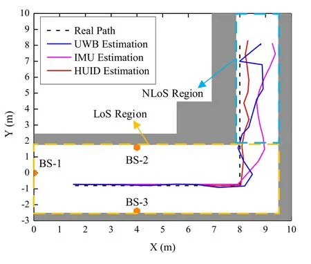
Figure 9.Experiment of indoor tracking paths.
Figure 10 presents the range of localization errors with different methods.Under the LoS condition,the distribution of most errors of UWB-based estimation and HUID-based estimation are within 0.2 m.However,the errors of IMU-based estimation are highly distributed due to the presence of the corner region.Under the NLoS condition,the errors of UWB-based and IMU-based estimation are unstable.On the contrary,the proposed HUID-based estimation method is robust and performs better.
2)Performance Comparison:We evaluate the localization performance of the proposed HUID by comparing with the existing EKF method [31,41].The EKF is based on a parameterized Bayesian model,which uses the priori state estimation and the feedback obtained from the measurement to estimate the posterior state.In our work,the parameters of the process and observation noise variances are set as 10−4and 10−3,respectively.Figure 11 investigates the CDF of the localization error of the HUID,EKF,UWB,and IMU estimation methods under LoS and NLoS conditions.At a CDF of 90%,the indoor localization errors of the proposed HUID are within 0.42 m,compared with that of 0.46 m for the EKF,1.02 m for the UWB,and 1.25 m for the IMU.Numerically,the MSE of estimation errors of different estimation methods under LoS and NLoS conditions are given in Table 2.The result shows that the MSE of localization errors of the proposed HUID system reduce by 12.96%,50.16%,and 64.92% compared with that of EKF,UWB,and IMU estimation under LoS and NLoS conditions,respectively.This proves the effectiveness of the proposed HUID indoor localization system.
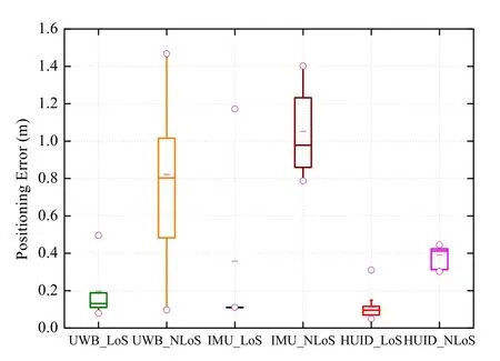
Figure 10.Box chart of the localization error with different locations estimation methods.
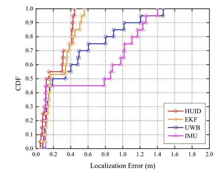
Figure 11.The CDF of localization errors with different methods.
VII.CONCLUSION
In this paper,a HUID indoor localization system is proposed for improving localization precision.Thesystem combines UWB and IMU localization methods with the DBN.Moreover,a RBF is adopted to estimate locations of the tag.The results of the identification of the random forest classifier and the mitigation of the random forest regressor show the positive effects on the UWB ranging and localization.Moreover,the experimental results show that the MSE of localization errors of the proposed HUID system reduces by 12.96%,50.16%,and 64.92% compared with the EKF,single UWB,and IMU estimation,respectively.The work of this paper contributes to the field of precise indoor localization.The more precise indoor localization technology for high-traffic scenarios is the goal of our future work.

Table 2.The MSE of estimation errors of different estimation methods under LoS and NLoS conditions.
ACKNOWLEDGEMENT
This work is supported in part by the National Natural Science Foundation of China under Grant No.61771474,in part by the Postgraduate Research &Practice Innovation Program of Jiangsu Province under Grant No.KYCX21_2243,in part by the Young Talents of Xuzhou Science and Technology Plan Project under Grant No.KC19051,in part by the Open Research Fund of National Mobile Communications Research Laboratory,Southeast University under Grant No.2021D02,in part by the Open Fund of Information Photonics and Optical Communications(IPOC)(BUPT).
杂志排行
China Communications的其它文章
- Quality-Aware Massive Content Delivery in Digital Twin-Enabled Edge Networks
- Edge-Coordinated Energy-Efficient Video Analytics for Digital Twin in 6G
- Unpredictability of Digital Twin for Connected Vehicles
- Endogenous Security-Aware Resource Management for Digital Twin and 6G Edge Intelligence Integrated Smart Park
- Digital Twin-Assisted Knowledge Distillation Framework for Heterogeneous Federated Learning
- Design and Implementation of Secure and Reliable Information Interaction Architecture for Digital Twins
