Integrated,reliable laser system for an 87Rb cold atom fountain clock
2023-02-20ZhenZhang张镇JingFengXiang项静峰BinXu徐斌PanFeng冯盼GuangWeiSun孙广伟YiMingMeng孟一鸣SiMinDaDeng邓思敏达WeiRen任伟JinYinWan万金银andDeSheng吕德胜
Zhen Zhang(张镇), Jing-Feng Xiang(项静峰), Bin Xu(徐斌), Pan Feng(冯盼), Guang-Wei Sun(孙广伟),Yi-Ming Meng(孟一鸣), Si-Min-Da Deng(邓思敏达), Wei Ren(任伟),Jin-Yin Wan(万金银), and De-Sheng L¨u(吕德胜)1,,†
1Key Laboratory of Quantum Optics and Center of Cold Atom Physics,Shanghai Institute of Optics and Fine Mechanics,Chinese Academy of Sciences,Shanghai 201800,China
2College of Materials Science and Opto-Electronic Technology,University of Chinese Academy of Sciences,Beijing 100049,China
3Aerospace Laser Engineering Department,Shanghai Institute of Optics and Fine Mechanics,Chinese Academy of Sciences,Shanghai 201800,China
Keywords: cold atoms,laser system,atomic fountain clock,reliability
1. Introduction
The cold atom fountain clock has been widely used as a precision frequency standard equipment in fields such as satellite navigation and basic physics since it was first developed in 1991.[1–3]As complex quantum systems, most fountain clocks are bulky and operate in a fixed laboratory environment. Most of the complexity of the fountain clock lies in the laser system,which is used for laser cooling and detection of cold atoms.[4–7]The output of the laser system is connected with the physical unit of the fountain clock by several singlemode polarization maintaining fibers.The stability of the laser power of the fiber output significantly affects the stability of the fountain clock.[8]
A reliable fountain clock with more portability would be very helpful for time keeping and time services.[9–12]In a previously developed fountain clock system,we integrated commercial lasers,laser amplifiers,frequency shifting components and laser beam splitter components into an optical table to create a transportable rubidium fountain clock. Long-term tests of the fountain clock were conducted in Shanghai and Beijing,with performance being similar in the two cities.[13,14]
In this article,we introduce an upgraded laser system with improvements to its vibrational resistance, thermal stability,and maintainability for developing a reliable, commercially available high-precision fountain atomic clock. Such a system is essential to promoting and applying high-precision cold atom quantum sensing devices,such as cold atom gravimeters,gravity gradiometers,and gyroscopes.[15–19]
The remainder of the article is organized as follows. Section 2 introduces the design principle and overall structure of the laser system. Section 3 demonstrates the design of the laser source component. In presenting the integrated operation of the overall system,the integrated design scheme of the tapered amplifier (TA), one of the core system components,is explained. Section 4 presents the design of the laser splitting and frequency shifting module, optimization of the thermal stability of the critical components, such as the reflector assembly,and the experimental results of the system’s thermal stability design. Section 5 presents the conditions and results of experiments conducted on system reliability and stability.Section 6 evaluates the performance of the laser system connected with the physical unit of the fountain clock. Section 7 gives concluding remarks.
2. Laser system design scheme
The function of the laser system in a rubidium fountain clock is to provide six-beam laser in optical fibers for cooling and trapping atoms and two-beam laser in optical fibers for detecting cold atoms. The cooling and trapping fibers contain the cooling laser frequency and the repumping laser frequency,which are independent for the two detection fibers. The laser frequency of the cooling component is locked to the crossover resonant peaks of|F=2〉→|F′=3〉and|F=2〉→|F′=2〉of the saturated absorption spectrum of the87Rb D2line,while the repumping component is locked to the crossover resonant peaks of|F=1〉→|F′=2〉and|F=1〉→|F′=1〉. After power amplification by the TA, the cooling laser beam is divided into seven beams,one for detecting and six for cooling.The frequency of the detecting light is red-detuned by approximately 3 MHz from the|F=2〉→|F′=3〉transition frequency,and the cooling light is red-detuned by approximately 18 MHz from the|F=2〉→|F′=3〉transition frequency.The frequency of the repumping laser is locked to the resonance line of the87Rb|5S1/2,F=1〉→|5P3/2,F′=2〉transition frequency.
The overall topological design of the optical path is nearly identical to that of the previous fountain clock.[13,14]We divided the laser system into four modules according to function to facilitate the replacement of modules and satisfy the maintainability requirement. Figure 1 is a schematic of the laser system. Input and output laser travels within an optical fiber outside modules,whereas laser beams travel in free space inside modules. Among the four modules, the cooling and repumping modules house the laser sources required for cooling and repumping light, the TA module amplifies the power of the cooling laser, and the laser-beam splitting and frequency shifting module splits and combines the laser beam,modulates the frequency and power,and couples the laser to the fibers of each beam.The following sections describe the design of each module in detail. We designed a structure for integration and reliability based on this scheme,as depicted in Fig.2.
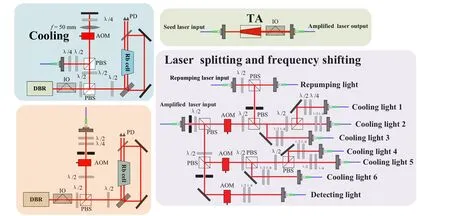
Fig.1. Optical schematic.
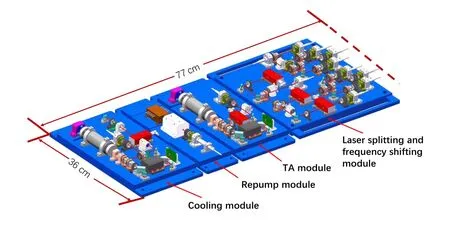
Fig.2. The three-dimensional model of laser system.
For the purpose of higher mechanical reliability, the entire system is assembled with as few adjustable mechanical components as possible and the positioning of all devices are reinforced with fasteners and glue. Eventually,the entire system is completely fixed with no adjustable components.
We adopted three methods for higher integration. First,we designed the structural size of each component as small as possible.Second,we used a folded optical path to optimize the layout and maximize the usage of space.Third,we verified the system’s structural strength through simulation to reduce volume and weight while satisfying the strength requirements.
The dimensions of the final laser system solution are 77 cm×36 cm. Consequently, our laser system is more compact than previous schemes and mechanically reliable.[2–13,13–22]
3. Laser source component
The cooling, repumping, and TA modules in Fig. 1 provide the laser source of the overall system,referred to collectively as the laser source component. The repumping module is structurally similar to the cooling component, and we introduced the cooling module and TA module. Photographs of these two components are shown in Fig.3.
In the cooling module, a distributed Bragg reflector(DBR) laser diode is chosen as the seed laser for its compact size and high mechanical stability compared with the external-cavity diode laser, typically used in frequency standards.[13,14,23–27]The output power of the DBR laser diode is approximately 100 mW. After passing through an optical isolator with 60 dB isolation,the laser beam is divided into two components by a polarization beam splitter. The lower-power beam is approximately 1 mW and enters a saturated absorption frequency stabilization optical path to lock the frequency of the laser to the|F=2〉→|F′=3〉and|F=2〉→|F′=2〉crossover resonant peaks of the saturated absorption spectrum of the87Rb D2line. The higher-power one is approximately 80 mW and passes twice through an acousto-optic modulator(AOM)to shift the laser frequency between 180 MHz and 240 MHz.[28]Then, such laser with the power of approximately 40 mW is coupled to a fiber. The output power of the fiber is approximately 20 mW.The output is injected into the TA through a fiber for amplification to more than 400 mW and then transmitted to the laser splitting and frequency shifting module through an optical fiber.
The difficulty of integrating the TA amplification module is the beam alignment and coupling in both directions,the high precise temperature control, the rapid heat dissipation, and the ultra-clean surface maintenance of the TA chip.In the previous fountain clock,[13,14]we used BoosTA series products produced by TOPTICA, with typical dimensions of 275 mm×115 mm×90 mm,with a mass of 3.9 kg.
We designed a TA module based on microscale packaging technology to integrate the TA. This design, as displayed in Fig. 4(a), consists of the injected seed laser coupling, the amplified outputs collimating, the thermal controlling and an interface of the chip’s current source.
Lens 1 is an aspherical lens(4.5 mm focal length)that focuses and injects the seed laser into the TA chip. Lens 2 is an aspherical lens(2 mm focal length)that collimates the magnified laser beam in the vertical direction. Lens 3 is a cylindrical lens (15 mm focal length) that shapes the output beam in the horizontal direction so that the final output beam is a nearly collimated Gaussian beam.
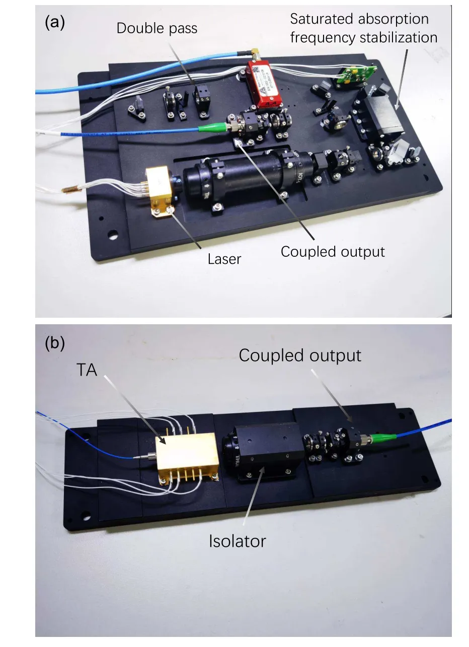
Fig.3. Photographs of(a)the cooling section and(b)the TA section.

Fig.4.Design and implementation of TA component integration:(a)optical principle design,(b)analysis of the output beam quality for verification of the optical scheme,(c)design scheme of the TA component integrated structure,and(d)photograph of integrated TA components.
We built an experimental system to verify the design scheme. The final output spot was monitored by a beam quality analyzer, as exhibited in Fig. 4(b). The laser system’s output quality is high and satisfies our application requirements. Accordingly, we designed a complete TA structure based on the butterfly packaging process, as depicted in Fig.4(c). In our design scheme, we integrated lens 1, lens 2,and the TA chip on the same base and connected them to a gold-plated stainless steel case with a thermo-electric cooler(TEC). These lenses, structural components, and TEC were jointed through laser welding after surface metallization. After debugging and assembling of the overall system, the case was filled with dry air and sealed to provide a stable operating environment. The final assembled TA component is presented in Fig.4(d). The dimensions and weight of the TA component are 55 mm×55 mm×21 mm and 0.1 kg, only 2.2% of the volume and 2.6%of the weight of the TOPTICA product.
As for the form of the TA output, a free-space output is applied instead of optical fibers, anticipating that the TA system will have a broader range of applications. Users can directly use free-space output or optical fiber-coupled output according to the needs of their systems. In our system, a fiber coupling component was added to the TA component to transmit the output laser to the laser splitting and frequency shifting module through an optical fiber. There are three advantages to this design. The first is decoupling the laser source component from the laser splitting and frequency shifting module,for convenient maintenance and device replacement. The second is that each module can be debugged separately during installation and adjustment to improve the efficiency of system integration and assembly. The third is that the beam quality of the laser output from the fiber is a nearly perfect Gaussian fundamental mode,ensuring that the optical fiber coupled output,AOM,and other components in the laser splitting and frequency shifting module work optimally, which improves the systemic reliability. Finally, the reliability of the TA component was verified by conducting thermal cycling tests and mechanical vibration experiments.There was no apparent change in TA component performance during the tests.
4. Laser splitting and frequency shifting module
Figure 5 is a photograph of the laser splitting and frequency shifting module. After beam split, the cooling laser from the TA passes through three AOMs with different driving frequencies,and then coupled into seven optical fibers for output. Three of them are used as upward cooling light,three for downward cooling, and the remaining one plays the role of detection light. The input repumping laser is split into two components: one coupled to the cooling light and the other coupled output to the physical system through another fiber.
The primary characteristic of the laser splitting and frequency shifting module is the high stability of the laser power from the input fiber to the output fiber. The stability of output laser power is related to the mechanical structure and thermal variation. The mechanical stability has been achieved by the structural design and assembly process while the thermal stability is still the difficulty and critical content of the laser system.
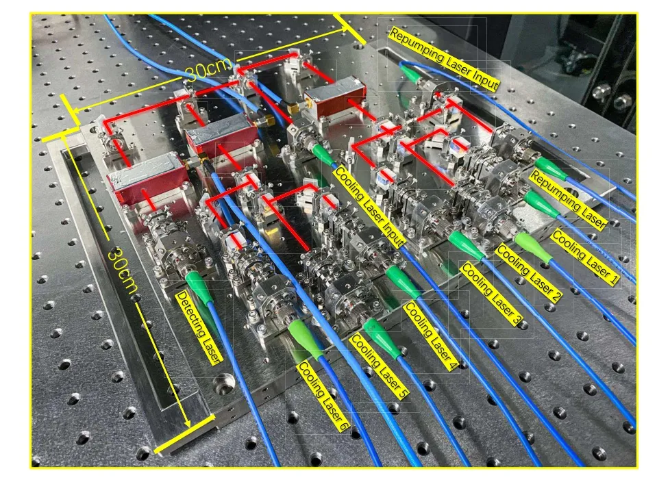
Fig.5. Photograph of the laser splitting and frequency shifting module.
From the input fiber to the output, the laser beam passes through polarizing beam splitters, AOMs, reflectors, wave plates,an optical fiber coupler,and other optical components.The effects of the temperature variation will change the beam orientation after the beam passes through the components,therefor it should be considered to maintain the stability of the output optical power. The structure and material of the most sensitive fiber coupling component were optimized while analyzing and optimizing the effect of the uniformity of the thermal expansion coefficient of the material on thermal stability. The results have been published elsewhere and are not described in this paper.[29]
In addition to the fiber coupling components, many reflective elements in the system deform under a temperature change(e.g.,the 45°C reflector component),misaligning the output beam and affecting the power output through the fiber coupling.
We performed a finite element simulation analysis of the thermal expansion of the existing reflector assembly, as depicted in Fig. 6(a). The structure is stainless steel, and the temperature fluctuations condition is heating by 20°C. The reflector structure experiences distinct forward tilting deformation under such conditions,resulting in beam deflection,so we optimized the structure accordingly. The optimized structure was simulated under the same material and temperature conditions, as depicted in Fig. 6(b). The optimized structure undergoes no noticeable deformation,and the tendency to lean forward is minimized. The effectiveness of our simulation and optimization was verified by designing a set of optical verification paths,as depicted in Fig.6(c). The reflector components before and after optimization were inserted into two sets of single-mode fiber optical coupling paths with the same structure and equal optical paths. We then evaluated the effect of the reflector structure on the thermal stability of the optical path based on the change in the output power. This is the same as the effect of the reflector assembly on the thermal stability of the complete laser splitting and frequency shifting module. We conducted two groups of temperature experiments,one for the large temperature variation and the other for the small change.
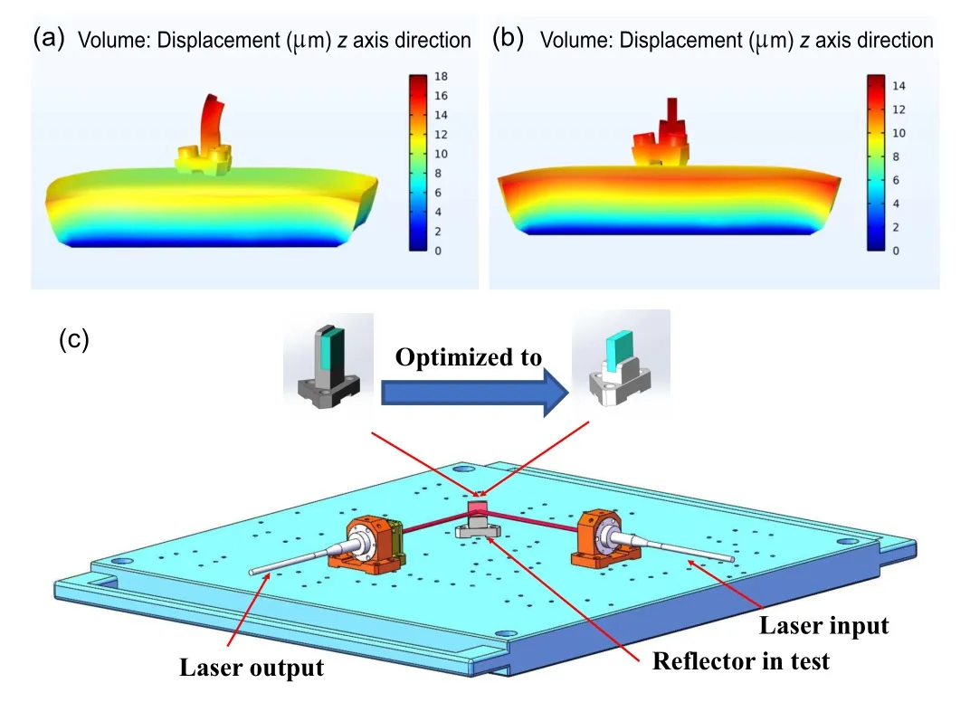
Fig.6. (a) Simulation of the thermal expansion of the reflector structure before optimization (1000× magnification), (b) simulation of the thermal expansion of the optimized reflector structure (1000× magnification), and(c)optical path design of the tests for verifying the optimization result.
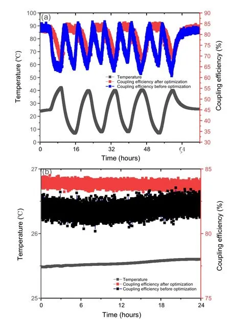
Fig.7. Validation tests on temperature for optimizing the thermal stability of the reflector structure: (a) validation results of tests with large temperature changes from 5°C to 43°C and(b)validation results of tests with small temperature changes of less than 0.1 °C.
The results of a large temperature change (in a range of 5°C to 43°C) are depicted in Fig. 7(a). The change in the coupling efficiency of the optical path on which the optimized reflector is located is approximately 25%smaller than before optimization. The experiment results for a small temperature change(less than 0.1°C)are depicted in Fig.7(b).The change in the output power of the optical path on which the optimized structure is located is less than half of that before optimization.It can be concluded that the thermal stability of our structure is optimal and the total stability of the output power is effectively increased.
5. Reliability tests and results
We conducted several tests to evaluate the reliability of our fountain clock’s laser system. Consistent with an environmental reliability testing standard of the space cold atomic clock,[23,24]the above system is to experience a temperature cycling test and a vibration test.In the thermal cycling test,the selected temperature conditions are varied from 8°C to 43°C,with a rate of 3°C per hour. We calculate the fluctuation in laser power of the cooling and detecting beams by the corresponding photo-current of fiber-in-built photodetectors,and experimental results are presented in Fig. 8. Because of the large amount of data, we present results for only three channels: two cooling lights and the detecting light. Under such conditions of temperature change, the peak-to-peak change rate of the output power of each light is less than 20%, and the output power of each light does not change appreciably during the test. These results satisfy our design and application requirements. Consequently,the thermal reliability of the overall laser system was successfully optimized.
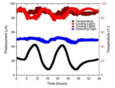
Fig.8. Test results of thermal reliability.
Another aspect of verifying reliability is a random vibration test for the entire laser system, with an order of magnitude of 6.11gRMS for a period of 90 s in the three directions ofx,y, andz. The changes in output power before and after vibration are presented in Table 1. The output power of the cooling and detecting light changes by less than 5%during the mechanical test, which can be compensated by changing the radio-frequency power of AOMs. These results indicate that the design of our laser system satisfies the mechanical reliability requirements.
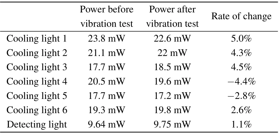
Table 1. Test results verifying mechanical reliability.
6. Functional verification
Random vibration and thermal cycling test illustrate that the laser system’s structural reliability ensures the power stability of the laser output from the fibers. Frequency stability is achieved by a saturated absorption spectrum. The detailed electronic design for frequency stabilization and the software control method have been described previously.[30]The swept spectrum of the frequency stabilization process is depicted in Fig.9.Figure 9(a)illustrates the spectrum of the cooling laser,and Fig.9(b)illustrates that of the repumping laser. The laser frequency is locked at the target peak after the software identifies the characteristic spectral line during the laser frequency scanning process. The fountain clock can be operated normally using the control system to drive the AOMs in the laser system based on the clock’s timing sequences. Figure 9(c)is a cold atom image obtained using our integrated laser system in the fountain clock revealing normal laser system function.
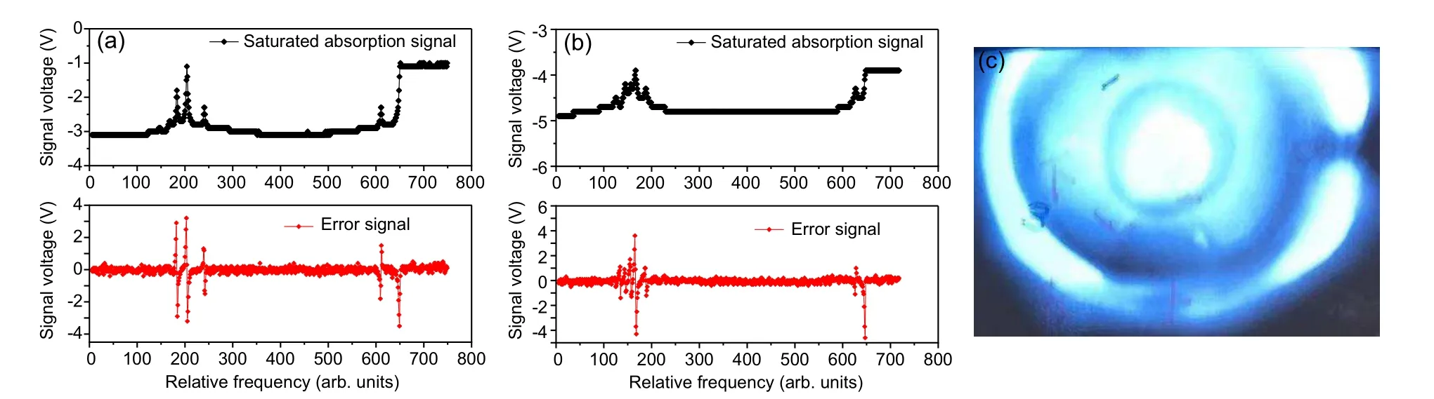
Fig.9. Experimental results of the functional verification of the laser system: (a) the frequency stabilization of the cooling laser, (b) the frequency stabilization of the repumping laser,and(c)a photograph of cold atoms cloud obtained by a magneto-optical trap.
7. Conclusion
In this paper, we developed an integrated and highly reliable laser system for87Rb cold atom fountain clocks, conducted performance evaluating tests, and verified system’s functionality with a fountain clock. This study establishes a technical foundation for achieving a new generation of longdistance transportable87Rb cold atom fountain clocks. This technology can be applied to high-precision cold atom quantum sensors,such as cold atom gravimeters and gyroscopes.
猜你喜欢
杂志排行

Chinese Physics B的其它文章
- LAMOST medium-resolution spectroscopic survey of binarity and exotic star(LAMOST-MRS-B):Observation strategy and target selection
- Vertex centrality of complex networks based on joint nonnegative matrix factorization and graph embedding
- A novel lattice model integrating the cooperative deviation of density and optimal flux under V2X environment
- Effect of a static pedestrian as an exit obstacle on evacuation
- Chiral lateral optical force near plasmonic ring induced by Laguerre–Gaussian beam
- Adsorption dynamics of double-stranded DNA on a graphene oxide surface with both large unoxidized and oxidized regions