Emitter discharge characteristics of verticaltube irrigation affected by various factors
2023-02-04,,,
, , ,
(1. College of Sciences, Shihezi University, Shihezi, Xinjiang 832003, China; 2. State Key Laboratory of Eco-hydraulics in Northwest Arid Region, Xi′an University of Technology, Xi′an, Shaanxi 710048, China)
Abstract: To examine the working principle of vertical tube irrigation, variations in vertical tube emitter discharge and their causes were analyzed in the laboratory experiment. The effects of the pressure head, initial soil water content, and tube diameter on the emitter discharge of the vertical tube were studied. The results show that quantitative relationship between the time and cumulative infiltration and emitter discharge of the vertical tube is obtained, and R2 is more than 0.98. Emitter discharge exhibits a positive and negative correlation with the pressure head and soil water content, respectively. Tube dia-meter has a nonsignificant effect on the emitter discharge. Changes of the soil water content around the emitter water outlet are the main causes of emitter discharge variations. In the experiments, the range of vertical tube emitter discharge is 0.056-1.102 L/h. The emitter of vertical tube irrigation automatically adjusts the soil water content and maintains the root zone soil water content within an appropriate range, which achieves continuous irrigation, and further achieves the effect of water-saving.
Key words: vertical tube irrigation;emitter discharge;pressure head;initial soil water content
Water resources are extremely crucial for the development of agriculture in arid and semiarid areas[1]. Therefore, many irrigation technologies have been widely used in water-deficient areas to achieve efficient water-saving, particularly subsurface irrigation techno-logy. In subsurface drip irrigation technology, a dripper was buried in the root zone to moisten the soil for crop growth[2], which can effectively reduce irrigation water consumption[3], promote crop growth[4], improve yield[5-6], and crop quality[7-8]. The water movement and distribution characteristics are critical for proper irrigation system design and accurate field application for subsurface drip irrigation.
Several theoretical and experimental studies have been conducted on the infiltration law of subsurface drip irrigation.BATTAM, et al[9]used the soil pit method to discuss the relationship between the emitter discharge and buried depth. Hydrus two-dimensional simulation of the water movement of subsurface drip irrigation[10]revealed that the soil water movement near the dripper depended on the hydraulic characteristics of the soil, dripper discharge, irrigation time, and buried depth of the dripper. This method has been used to predict the spatial distribution of soil water content and the law of wetting front transport. Studies [11-13] have shown that the soil texture, pressure head, depth of buried drippers, and pipe laying interval considerably affect the emitter discharge of subsurface drip irriga-tion. The drip irrigation discharge is a crucial factor in the design and management of drip irrigation systems, and it also affects the distribution of water in the soil.
In subsurface drip irrigation,soil water content changes periodically with irrigation. The soil in root zones experiences dry and wet alternation in a short time before and after irrigation, which causes drought and flood stress in the crop roots and increases the occurrence of pests and diseases. To avoid the impact of soil water content fluctuations on crop growth, soil moisture parameters and crop physiological parameters are generally monitored, and meteorological parameters are used to simulate and calculate appropriate irrigation time and irrigation volume. However, optimization of the indirect methods of measurement and calculation is difficult and influences the effect of water-saving irrigation. Alternating irrigation causes blockage of the original dripper structure[14], thus adversely affecting the dripper flow.
In past years, studies determined that continuous irrigation was more suitable for crop growth, and it could maintain the soil water content in the root zone within a suitable range. Such irrigation emitters included porous ceramic[15]and vertical tube emitters. The porous ceramic emitter was buried in the ground under micro pressure or no-pressure conditions, and the discharge of the emitter was regulated by the soil water content, maintained the soil water content within a sui-table range in the root zone, and beneficial to the distribution and growth of crop roots. However, the porous ceramic emitter has a larger area of passage and multiple channels may cause clogging.
Vertical tube irrigation[16]is a novel subsurface irrigation technology. The emitter is a PVC tube 10-20 mm in diameter, which is buried vertically in the soil. The emitter pressure head is 2.0 m below the surface of the soil. The upper end of the vertical tube emitter is connected to the water supply pipelines, and the lower end is open and contacts with soil very close, forming a water-soil interface. During the infiltration process, water passes through the emitter and reaches the soil-water interface. Analysis of variations in emitter discharge under vertical tube irrigation and their causes of discharge change of emitter is crucial for the development of the technology in the future.
1 Material and methods
1.1 Experimental equipment and soil samples
The experiments were performed at the State Key Laboratory of Eco-hydraulics in Northwest Arid Region, Xi′an University of Technology. The experimental setup comprises the Markov bottle, soil contai-ner, vertical tube emitter, and soil moisture sensor probes, which is depicted in Fig.1. The Markov bottle with a diameter of 5 cm and height of 50 cm was used as the water supply device. The vertical tube emitter with inner diameter of 12 mm and length of 330 mm was made of polyvinyl chloride. The experiment was performed in a polymethyl methacrylate container with dimensions of 45 cm × 45 cm×50 cm (length×width×height). Small holes of 20 mm (hole spacing, 5 cm) diameter were drilled on the sidewall of the soil container to pass soil moisture sensors. The soil moisture sensor probes (EC-5, Decagon, USA) were placed at different locations in the soil near the vertical tube emitter.

Fig.1 Schematic of experimental apparatus
Soil samples for the experiment were collected from Xi′an, Shaanxi, China. The soil samples were air-dried, mixed, and sieved through a 2 mm mesh. The soil texture was determined using a laser particle size analyzer (MS2000, Malvern, UK). According to the international standard for soil texture classification, the soil sample was silty loam (clay of 9.78%, silt of 48.10% and sand of 42.12%). The bulk density of the soil sample was 1.35 g/cm3, and the soil saturated water content and the soil-saturated hydraulic conducti-vity (estimated with RETC) were 0.469 cm3/cm3and 0.006 cm/min, respectively.
1.2 Experiment method and measurement content
In the experiments, three tube diameters (10, 12, and 16 mm) of the emitter, three pressure heads (0.6, 0.9, and 1.2 m), and initial soil water contents (9.8, 11.9, and 23.8 cm3/cm3) were selected. When designing the experiment, the method of uniform design was taken as an experiment. A total of seven groups were formed in the experimental schemes as shown in Tab.1. (The corresponding experimental schemes for pressure headH, initial soil moisture contentα, and vertical tube diameter changesdwere 1, 2, and 3; 1, 4, and 5; 1, 6, and 7, respectively). Each test protocol was repeated three times, that is, 21 groups of tests were performed.

Tab.1 Experiment scheme
According to different experiment schemes, the soil was uniformly compacted into 5 cm layers, which required close contact and totaled nine layers of soil, 45 cm deep. The water outlet of the vertical tube emitter was located at a depth of 20 cm from the soil surface (the depth of the soil-water interface). The soil surface was covered with a 0.5 mm film for reducing water evaporation. The pressure head of the vertical tube emitter was the height difference between the air inlet of the Markov bottle and the water outlet of the vertical tube emitter. The infiltration time was measured using a stopwatch. During observation, the observation data (the Markov bottled water level) corresponding to different infiltration times shall be recorded according to the principle of close first and thinning. The observation time was less than 20 min, and the time interval was 5 min. The time intervals were 10 and 30 min, for infiltration times of 20-60 min and 60-420 min, respectively. The average of the three measurements was considered to be the experi-ment result. In Scheme 1, the changes of soil water content over time were monitored. With the center of the emitter water outlet as the origin, the vertical direction as the z-axis, and the horizontal direction as thex-axis, four soil moisture sensor probes were arranged, and the coordinates (5, 0), (5, 2), (4, -5), (3, -7) were recorded as points 1, 2, 3, and 4. The soil moisture sensor measures soil moisture data every 5 min.
1.3 Data analysis
The Philip infiltration model was used to construct the empirical formula of the cumulative infiltration and infiltration time,
I=St0.5+At,
(1)
whereIis the cumulative infiltration amount (L),tis the infiltration time (h),Sis the soil infiltration rate (L/h0.5), andAis the infiltration constant (L/h).
According to formula (1), the emitter discharge of the vertical tube irrigation is expressed as follows,
q=0.5St-0.5+A,
(2)
whereqis the emitter discharge (L/h) of vertical tube irrigation.
Officers of the bodyguard were often sent on all sorts of secret and difficult errands, and such errands had a curious way of becoming necessary when Nur Mahomed was on duty
2 Results
2.1 Change of cumulative infiltration over time
The change of the cumulative infiltration of the vertical tube emitter over time is depicted in Fig.2. After completion of infiltration (t=7 h), the cumulative infiltration order was as follows: scheme 3, 2, 5, 1, 4, 6, and 7. The maximum cumulative infiltration was 1.504 5 L, and the minimum was 0.519 1 L.
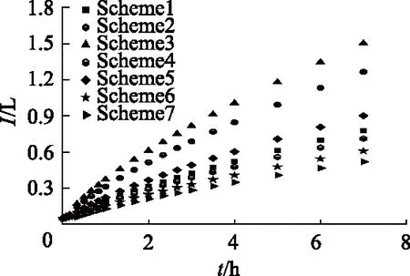
Fig.2 Cumulative infiltration over time
According to the experimental data in Fig.2, the quantitative relationship between the cumulative infiltration and infiltration time was established according to the Philip infiltration formula (1). The fitting parameters were depicted in Tab.2. The determination coefficientsR2(P<0.05) were all more than 0.980, which indicated that the model fitted well. The soil infiltration rate (S) and stable infiltration rate (A) were distinct for different schemes. The parameters (SandA) of Scheme 3 were the largest and the parameters of scheme 7 were the smallest.

Tab.2 Philip infiltration formula fitting parameters
2.2 Change of emitter discharge under vertical tube irrigation over time
The change of the emitter discharge at different times according to formula (2) is depicted in Fig.3. The emitter discharge gradually decreased with time. The pressure head, initial soil water content, and tube diameter of the emitter were in the range 0.6-1.2 m, 9.8-23.8 cm3/cm3, and 8-12 mm, respectively, and the emitter discharge was between 1.102 and 0.056 L/h. When the initial water content of the soil was 9.8 cm3/cm3and the tube diameter of the emitter was 12 mm, the emitter discharge changed with infiltration time under different pressure heads (schemes 1, 2, and 3), as depicted in Fig.3. The emitter discharge gradually increased with the increase in the pressure water head, and the earlier the time to reach a stable emitter discharge, the greater the stable emitter discharge.

Fig.3 Variation of emitter discharge over time under different pressure heads
When the pressure head and the initial soil water content were 0.6 m and 9.8 cm3/cm3, respectively, the tube diameters of emitters were different among schemes 1, 4 and 5, and the emitter discharge changed with time, as depicted in Fig.4.

Fig.4 Variation of emitter discharge over time with different tube diameters
In the initial infiltration period (t<1 h), the initial emitter discharge had a positive correlation with the tube diameter of the emitter, and the initial emitter discharge increased with the increase in the tube dia-meter. Because the infiltration time increased, the smaller the difference between the emitter discharges, the closer the stable emitter discharge. In vertical tube continuous irrigation, the change in the tube diameter had a small effect on the emitter discharge, especially the stable emitter discharge.
The changes of the emitter discharge over time under different conditions of initial soil water content (schemes 1, 6, and 7) when the pressure head and the tube diameter of the emitter were 0.6 m and 12 mm, respectively, are depicted in Fig.5.

Fig.5 Variation of emitter discharge over time under different soil water contents
At the beginning of the infiltration, the larger the initial soil water content, the smaller the emitter discharge of the vertical tube. As the infiltration time increases, the smaller the difference between the emitter discharge, the closer the stable emitter discharge. During the entire infiltration process, the larger the initial soil water content, the smaller the change in the emitter discharge of the vertical tube. This indicates a negative correlation between the initial soil water content and the emitter discharge of the vertical tube.
2.3 Driving mechanism of the soil matrix poten-tial on the change of emitter discharge
EC-5 was used to determine the change of soil water content at different locations during the infiltration process of Scheme 1. Fig.6 depicts the relationship between the soil water content and the emitter discharge over time during the infiltration of the vertical tube irrigation.

Fig.6 Relationship between soil water content and emitter discharge over time under vertical tube irrigation
At the beginning of the infiltration, the water did not move to the test point, the soil water content retained the initial value. With the diffusion of water, the soil moisture at different locations gradually increased with the infiltration time. During the infiltration process, water diffused outward and the water of the vertical tube was at the center. The soil water content at the measurement point 3 (buried deep below the emitter outlet) and point 1 (buried deep at the same height as the emitter water outlet) increased rapidly, and the base stabilized after the soil moisture reached a certain level.
Owing to this, the water diffused from the water outlet of the vertical tube emitter was affected by the potential of gravity, so the soil water content at point 3 below the emitter water outlet changed the fastest. At point 1, the soil water content was mainly affected by the soil matrix potential, and the water gradually diffused to the horizontal direction, therefore, with the increase in the infiltration time, the soil water content gradually increased. Point 4 was located below the emitter water outlet, but it was far away from the emitter water outlet and the water diffusion was slow, so the soil water content changed slowly. Water moved to point 2 (the location of this Point was higher than the emitter water outlet) and the effect of gravity potential needed to be overcome. Therefore, the soil water content changed the slowest.
Water diffusion fromthe vertical tube emitter was affected by the soil matrix potential, pressure potential, and gravity potential. During the infiltration process of vertical tube irrigation, water flowed out from the emitter water outlet and formed a high soil moisture area around the emitter water outlet of the vertical tube, and the soil matrix potential decreased rapidly in this area. However, water still slowly flowed out of the emitter water outlet and diffused into the surrounding soil by the pressure potential and gravity potential. The closer the point is to the water outlet, the faster the soil water content changes and the faster the soil matrix potential decreases vice versa.
During the infiltration process, a region with high soil water content was firstly formed around the emitter water outlet. This directly led to a rapid decrease in the emitter discharge of the vertical tube irrigation. Howe-ver, the farther the region was from the emitter water outlet, the water continued to diffuse outward because of the potential difference of the soil, thus, the vertical tube emitter continued to supply water with a smaller discharge.
3 Discussion
The pressure water head and the initial water content of the soil considerably influence the emitter discharge of the vertical tube, whereas the emitter diameter of the emitter has a small effect on the emitter discharge. The water content of the soil around the emitter water outlet of the vertical tube irrigation increases with the infiltration time, which causes the soil matric potential to gradually decrease. The movement of water in the horizontal direction is affected by pressure and matric potentials. With the increase of the soil water content, the effect of the soil matric potential decreases. The closer the vertical direction is to the emitter water outlet of vertical tube irrigation, the water moves more downward under the action of the pressure, matric, and gravity potentials. As the soil moisture content increases, the soil matric potential gradually decreases, so the water diffusion gradually slows. During vertical tube irrigation, the soil water content at the emitter water outlet is high, the soil matric potential is reduced, and the outward movement slows water even inhibiting the water to a certain extent. But the effects of gravity and pressure head promote the slow migration of water to ensure continuous irrigation.
The most suitable pressure head for vertical tube irrigation is less than 2.0 m, which exhibits a significant energy-saving effect compared with subsurface drip irrigation[8]. Compared with another emitter[10,14-16], the vertical tube irrigation emitter has a simple structure and larger size, and the tube diameter is 10-20 mm. At the same time, vertical tube irrigation avoids the soil from appearing wet and dry alternately before and after irrigation, which may be conducive to crop growth[17]. Nevertheless, the lower end of the vertical tube emitter is an open water outlet, which is not easily blocked.
This study only analyzed the working principle of vertical tube irrigation, and the influence of pressure water head, initial soil water content, and diameter on the emitter discharge of vertical tube irrigation. In future studies, the effect of the emitter outlet burial depth and soil texture on infiltration should be consi-dered to establish a more universal law.
4 Conclusions
1) The cumulative infiltration of vertical tube irrigation gradually increases with the infiltration time. An empirical formula for the cumulative infiltration and infiltration time is constructed, andR2is more than 0.98.
2) The emitter discharge of the vertical tube gra-dually decreases with the infiltration time. The emitter discharge has a positive correlation with the pressure head and a negative correlation with the soil water content.
3) The change in the soil water content near the emitter water outlet is the direct cause of the change in the emitter discharge of vertical tube irrigation. The automatic adjustment of soil water content can be achieved through the coupling effect between the emitter discharge of the vertical tube irrigation and the soil water content, thus providing active irrigation.
