Valve Train Dynamic Design and Verification
2023-01-31CAOXuYINJiandongLIUShengqiangYAOJunwei
CAO Xu, YIN Jiandong, LIU Shengqiang, YAO Junwei
(Ningbo Geely Royal Engine Components Co., Ltd., Ningbo 315400, Zhejiang, China)
Abstract:Valve train dynamic behaviors need to be considered at the beginning of the engine mechanical design, especially during choosing valve spring parameters. From parameter definition to simulation, the valve train parameters around dynamic performance are determined step by step. The valve train dynamic test is done finally to verify the design result since it is a such important facet for valve train design. And reliability from mass production and product life view must be considered during whole design process too.
Keywords: valve train; dynamic simulation; dynamic verification
1 Introduction
Valve train dynamic performance is critical because its results will influence not only component material and structure but also valve train layout confirmation. Sufficient valve train dynamic consideration is necessary at early design stage to prevent from following issues like wear and NVH at the later design stage. Therefore,dynamic calculation must be started as early as possible. And it is better to do dynamic test for double check since valve train dynamic performance is such an importance topic. During the design around the valve train dynamic performance,several trade-offs must be considered to get a balancing point as the final option.
The first trade-off is between engine thermodynamic performance and valve train dynamic behavior. This is mainly displayed on the choice of valve lift curves. The successful valve lifts are always options after considering both facets.
After valve lift curves are confirmed,the second trade-off occurs which is between friction loss and contact loss,separation happening among valve train components. When valve lift curve and mass of valve train components are confirmed,lower friction can be achieved mainly through decreasing the valve spring force. Although lower spring force can improve the friction and wear performance,it means to decease the safety margin against contact loss at the same time. Safety margin here meansFs/Fi(Fsis spring force,Fiis inertial force),which is used to assess the possibility of contact loss. Lower safety margin must require the higher product accuracy,lest contact loss happens in practical application. The more accurate product normally means higher cost requirement. What need be paid attention here is that friction of valve train will influence whole timing system friction loss.
In practical application,more facets,such as package and weight,must be considered to confirm these parameters around dynamic behavior. The final option of valve train design should be the one after considering all these facets.
2 Valve lift curve design and related spring force choice
Valve lift curve is one of the key outputs of valve train dynamic calculation. Final option must meet both engine thermodynamic performance and dynamic behavior. Several round calculations are done normally to get the optimum option. Since it is not the main topic in this article,the valve lift curves are directly shown here,see Figure 1. Following design and verification will be done based on it. From the view of valve train dynamic performance,acceleration is a more visual expression than valve lift. Therefore,acceleration profiles are shown together here although it can be gotten from differential calculation of valve lift[1].
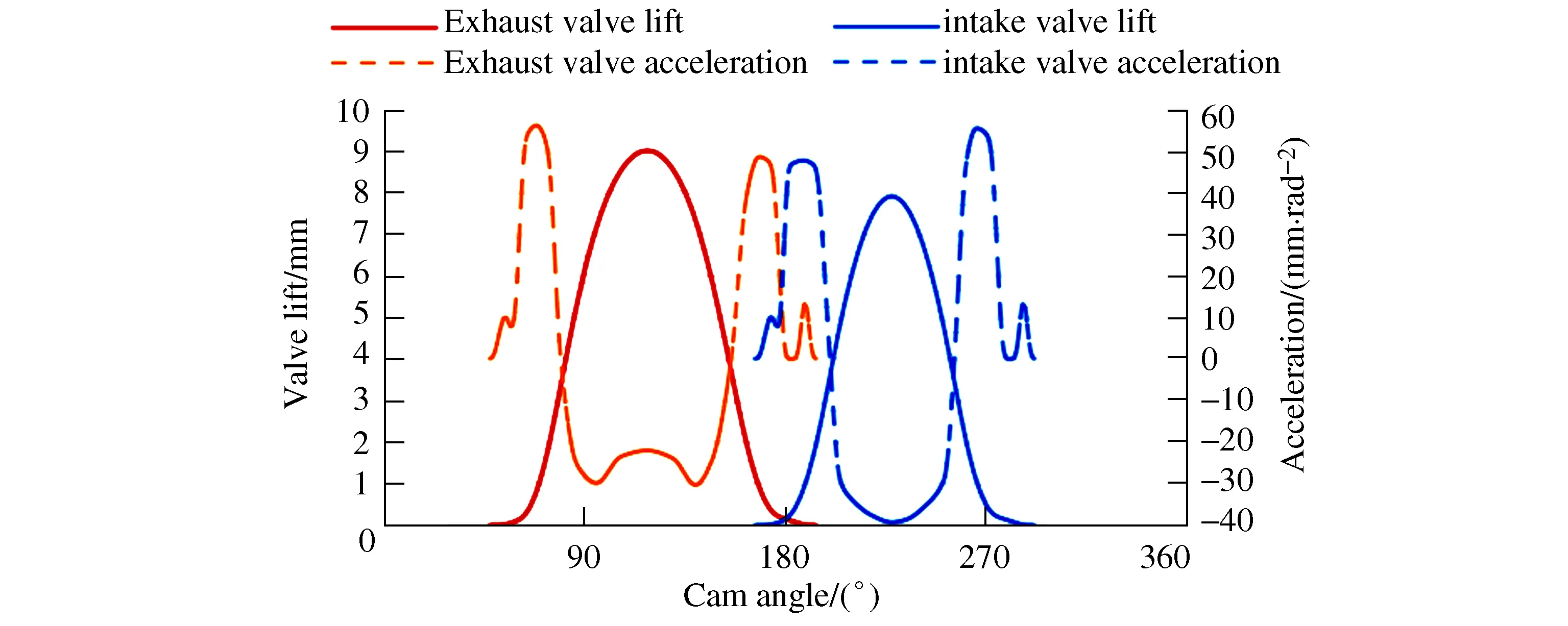
Figure 1 Valve lift and acceleration
From above acceleration curve,it can be seen that negative acceleration of intake valve is bigger than it of exhaust valve. And intake motion mass is bigger than exhaust side too. It means that bigger spring force around maximum lift point is required on intake side than on exhaust side,so that contact loss can be prevented at high engine speed. Here,spring force at max. lift is called asF2and preload spring force when valve is closed is called asF1. Normally,dynamic calculation needs the preliminaryF1andF2as input data. Then some rounds calculation must be done to find out the optimal option. The appropriate initialF1andF2can reduce the calculation rounds. Here is suggestion how to choose the initialF1andF2.
TheF1is separated into 4 portions andF1,as sum of these portions,can be gotten after confirming the values of these portions,f1-f4. Here is mean of these portions:
f1is component force to ensure gas sealing;
Why were you such a fool as to let yourself be thrown in? Didn t you know that fire burns? And in a very few minutes nothing was left of the rabbit but a few bones
f2is component force against initial hydraulic lash adjuster force;
f3is spring force tolerance;
f4is dynamic reservoir and decay reservoir to prevent abnormal opening of valve at extreme conditions.
It is clear that biggerf4can bring more safety margin to prevent valve abnormal opening. But biggerf4means more friction loss. To ensure both valve sealing and lower friction,f1-f4should be chosen carefully,as shown in Figure 2. In current application,the exhaust spring needs biggerF1in comparison to intake spring. That is mainly because exhaust valves need bigger spring force to push against gas back pressure.

Figure 2 Choice of spring preload F1
The chosenF2must meet requirement of preventing contact loss happening in max. engine speed. In other words,spring force must exceed the inertial force in opposite direction to ensure there is no separation between any contacting components during valve lift event. Therefore,F2preliminary choice can be estimated according to inertial force which related to negative acceleration and mass of reciprocating motion. The following formula can be used for preliminaryF2choosing.
(1)
Where:mis total mass of motion parts,g;ais minimum negative acceleration value,mm/rad2;ris max. engine rotation speed per minute,r/min;τis for two-stroke or for four-stroke.
Though we know that minimum safety margin point doesn′t always happen at maximum valve lift,we still can estimateF2as preliminary choice since the point is not so far normally. And the preliminary choice is only initial input and more elaboration will be done later according to dynamic calculation result. The“m”value in formula(1)includes mass of valve,cotter,spring retainer,valve spring and rock arm/tappet. The mass of rock arm and spring can′t be used directly because rock arm has different motion from valve and spring doesn′t involve the motion entirely. Here,the equivalent mass of rock arm which joins the reciprocating motion need be extracted. The mass proportion of spring which attends the reciprocating motion need be estimated too.
Valve spring force will affect the friction loss of valve train and timing system. It looks like the minimumF2just against contact loss is the best option for the design. But it is only true from mathematic view. We must think more than purely dynamic calculation result. More facets need be considered for practicalF2choice,for instance product tolerance,spring force decay and even package for spring.
3 Dynamic simulation and result analysis
Based on input of mass,valve lift curve,optimized spring force and gas force on valve,the simulation model is built,see Figure 3. Besides spring force feasibility check,simulation focuses further topic about stress and force.
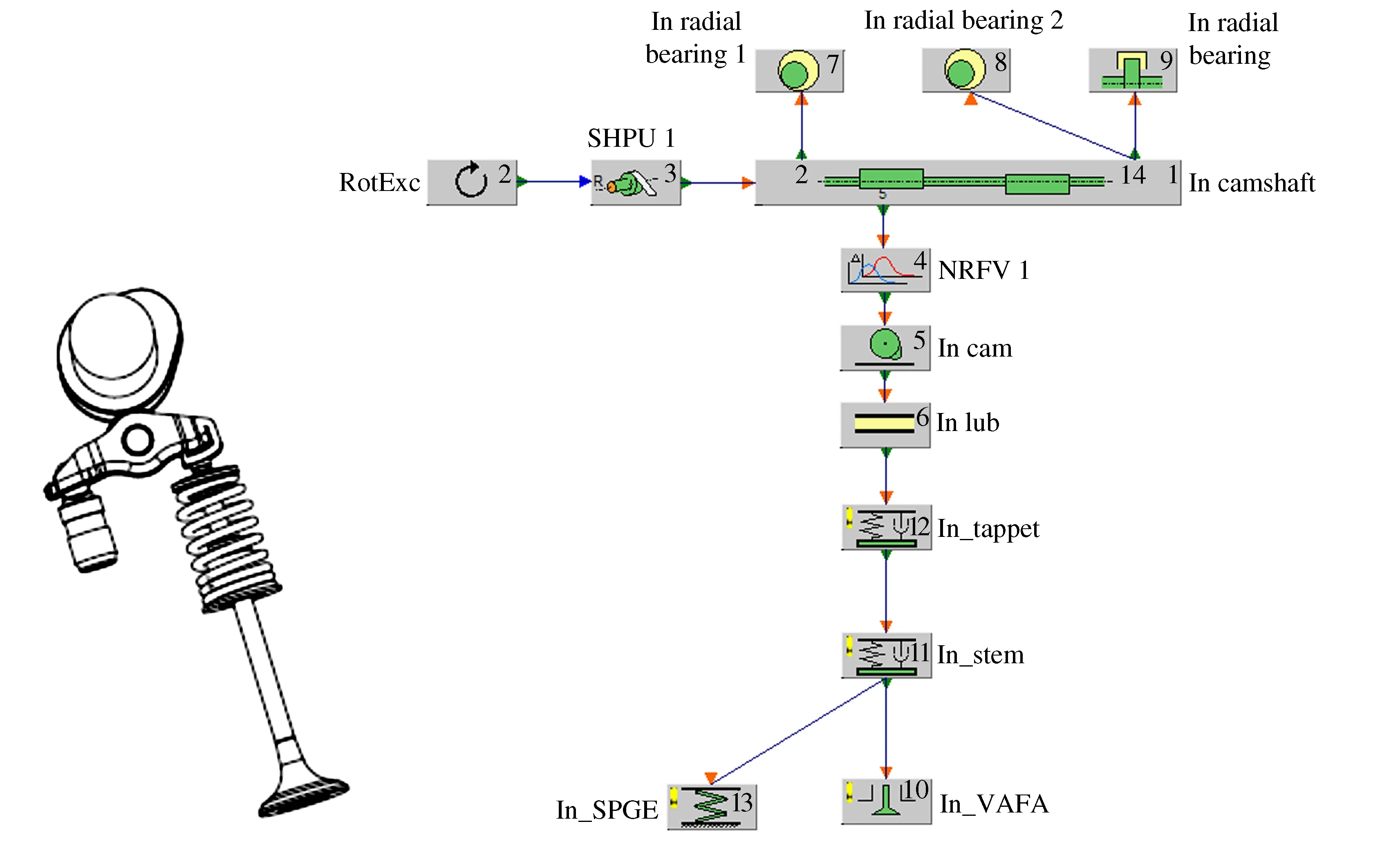
Figure 3 Model of valve train simulation
Figure 4 is the contact stress values along engine speed and related assessment between cam and roller of rock arm. Among whole engine speed range,the stress is under the allowable stress of current material. And Figure 5 shows the contact stress between rock arm and valve which meets the requirement too.
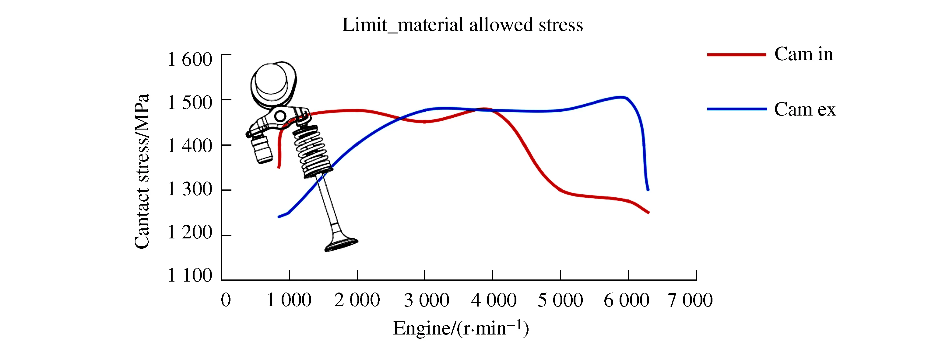
Figure 4 Contact stress between cam and roller

Figure 5 Contact stress between valve and rock arm
Stress between rock arm and HLA(hydraulic lash adjuster)is much lower than allowable stress. In comparison to stress requirement,HLA min. axial force should be paid more attention here. The force should be big enough to prevent unnormal opening of valve at extremely high oil pressure[2]. Figure 6 shows the HLA min. axial force along engine speed. This force is mainly assessed under engine rate speed. Force values here meet the requirement of limit which is estimated according to current application. It can be seen that force on exhaust valve can′t meet the force requirement if fuel-cutting speed is involved too. But we still think that it is acceptable after analyzing all these facets setting in simulation model because the worst condition,ultimately oil pressure due to extremely low temperature,won′t appear together with transient over speed in practical work. After thinking over all these facets,the final spring force is kept.According to simulation result,spring margin is 1.46 for intake and 1.73 for exhaust at max. engine speed.
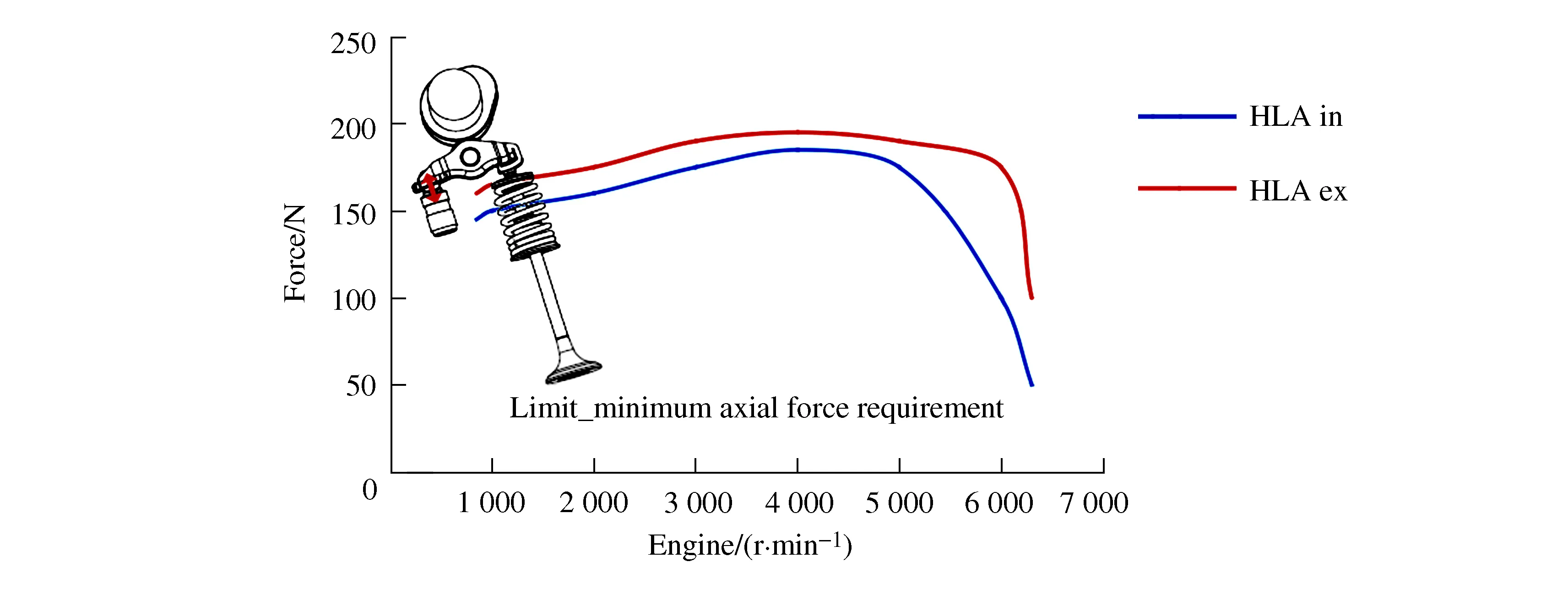
Figure 6 Axial force on HLA
4 Verification of valve train dynamic performance
Spring surge and components′stiffness,especially rock arm stiffness will bring vibration to valve train system and will influence dynamic performance eventually. Parameters referring to vibration in simulation model are only the approximation and it is difficult to know how accurate it is without any test verification. Therefore,dynamic test rig is built to verify the valve train dynamic performance and double check the feasibility of the dynamic design around valve train. The simulation model can be calibrated during this process too.
Figure 7 shows the test rig built for the verification. A motor is used to drive the camshaft and two laser sensors are used to measure the valve displacement to cylinder head. Based on valve lift data,the valve speed and acceleration can be gotten to assess the dynamic performance.
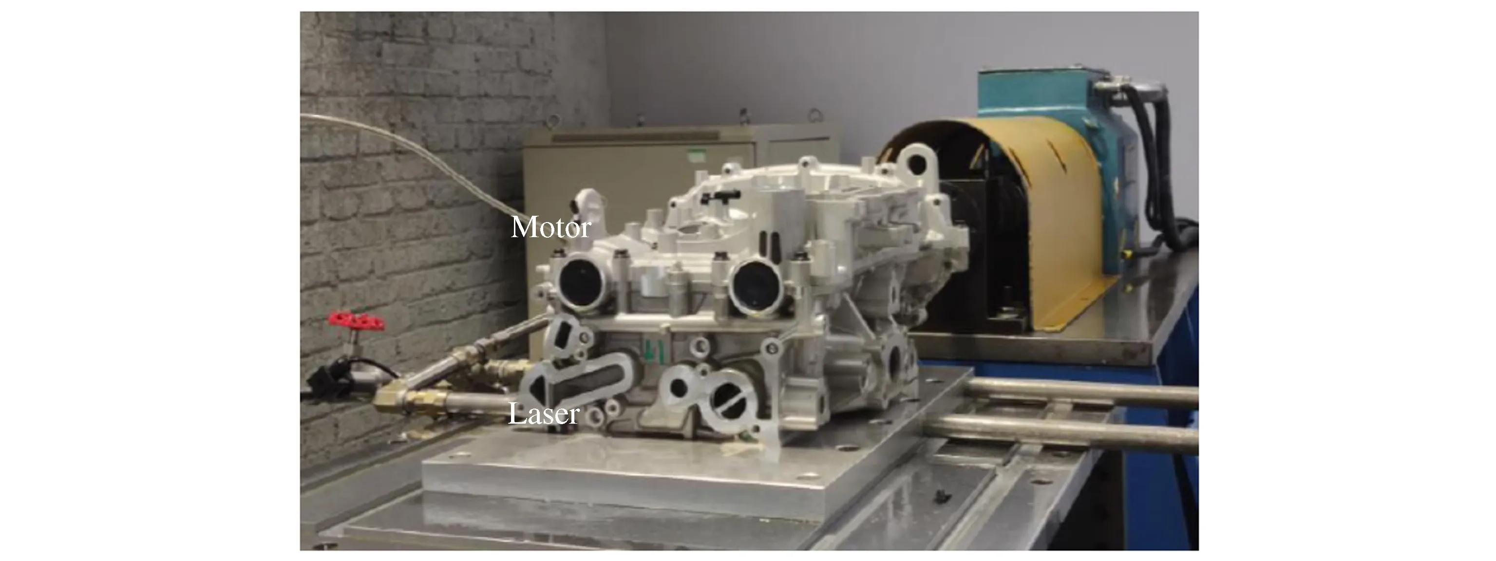
Figure 7 Test rig for valve train dynamic measurement
To verify the feasibility of test rig,the lower engine speed,700 r/min,is used to check and compare the measured acceleration with calculated value firstly.The low engine speed is chosen for preliminary verification because the vibration is so lower in this speed that it can be neglected in this condition. And the reliability of measurement can be assessed purely without thinking too much influencing facets around vibration. The result in 700 r/min appears good coherence between simulation and measurement,see Figure 8. It need be paid attention here that back-pressure force isn′t involved in this test rig.
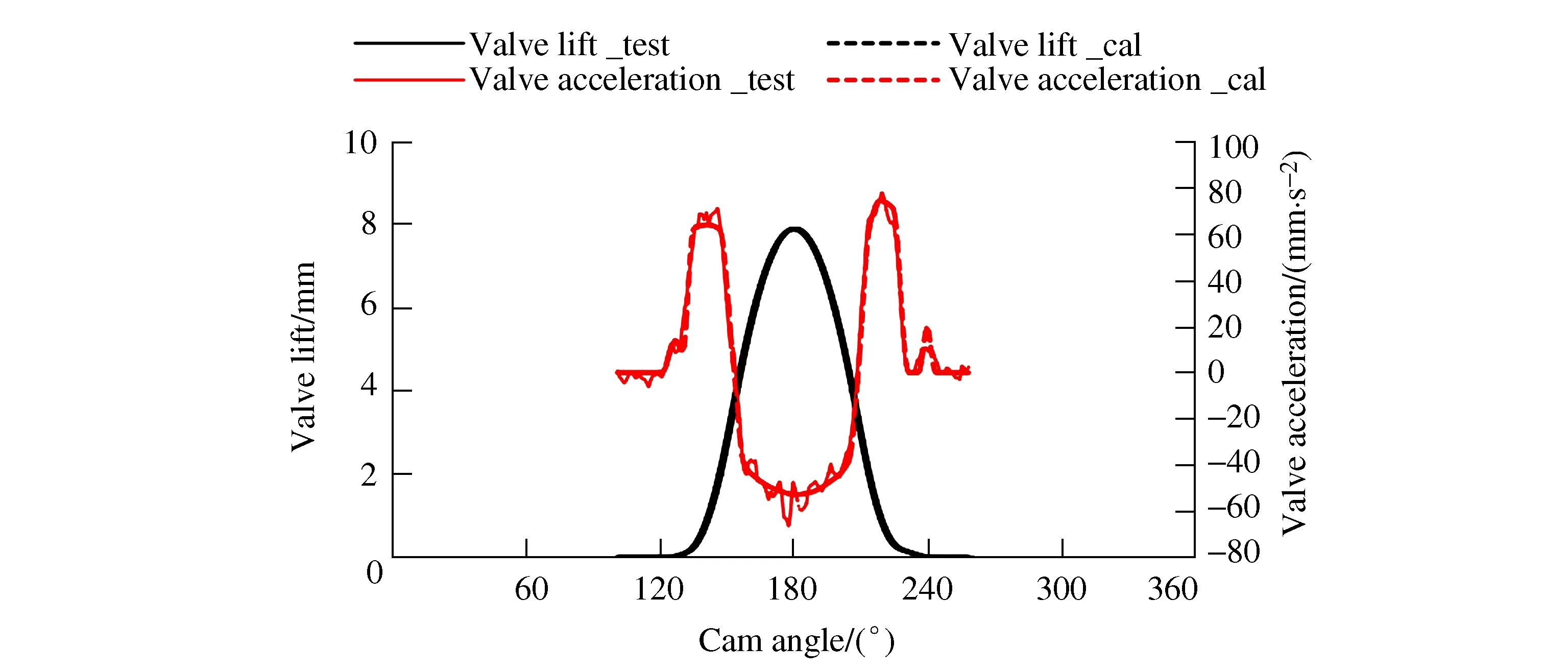
Figure 8 Measurement feasibility confirmation
After confirming the feasibility of test rig,the valve dynamic measurements in whole speed range are done to assess the valve train dynamic performance. Above Figure 9 sees the max. acceleration and peak negative acceleration along engine speed. Max. positive accelerations of intake and exhaust side are at the same level. But intake negative acceleration is definitely bigger than exhaust value,which is especially obvious at high engine speed. This can be explained through Figure 1 that shows the designed negative acceleration on intake side is obviously lower than it on exhaust side. Here,estimated safety margin can be gotten by measured negative acceleration,motion mass and spring force,which is 1.23 on intake side and 1.90 on exhaust side when engine run in maximum speed. Here safety margins have gaps with simulation result,1.46 for intake and 1.73 for exhaust. The gaps are caused by condition change,without pressure change in test rig and tolerance influence.
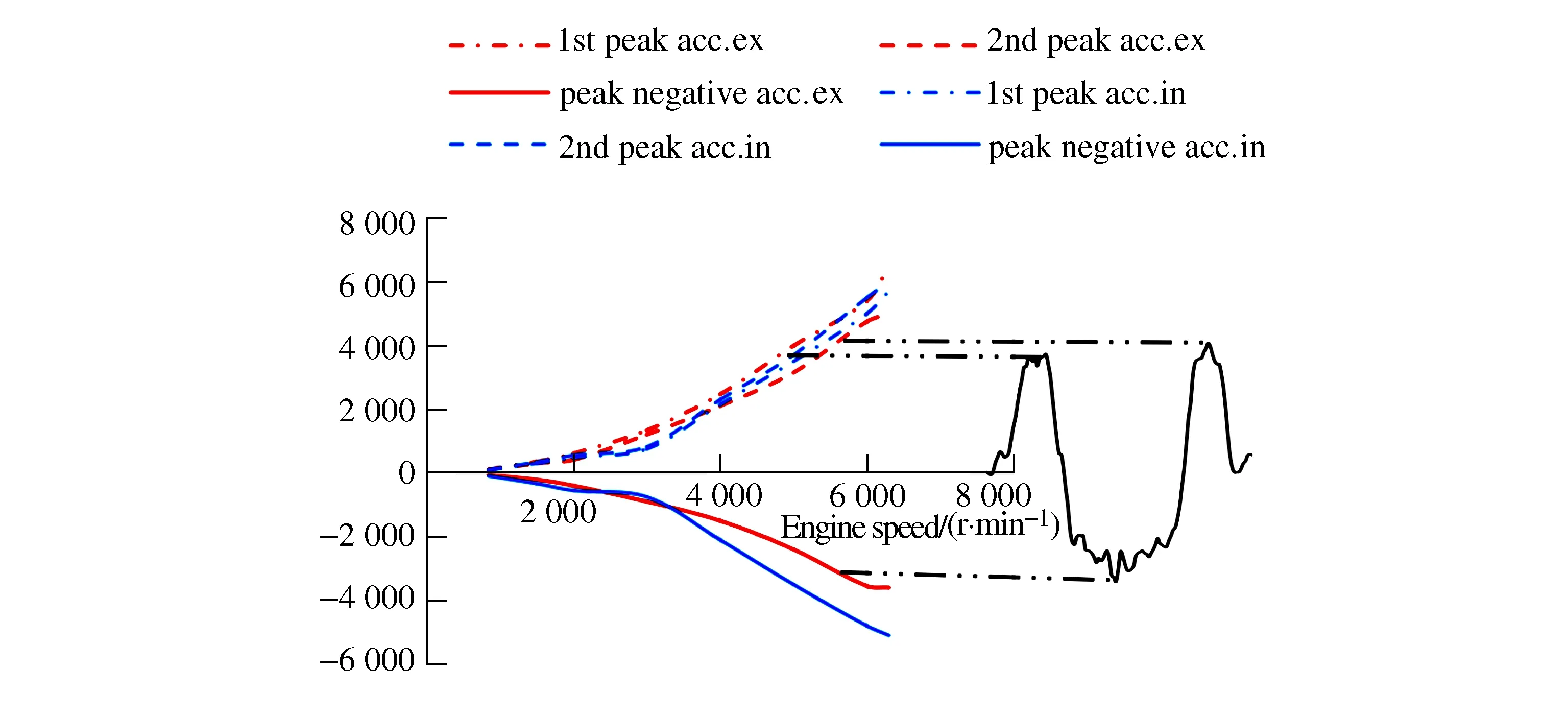
Figure 9 Measured acceleration data
It looks like that safety margin on exhaust side is adequate and there is potential to be reduced for lower friction. As we know from previous chapter,F1needs to be kept and onlyF2and spring rate,kcan be reduced here. According to analysis,the exhaust valve spring rate needs to decrease to half of original design in order to decrease safety margin from 1.73 to 1.30 with fixedF1. The change of spring needs to reduce spring coil diameter and to use more expensive material for improving its fatigue resistance. After comprehensive consideration,the original exhaust spring design is determined as the option finally from cost effective view.
While turning to intake design,the 1.23 already near to margin if the production tolerance and delay due to life are considered.
To double check the contact loss,strain gauges are stuck to rock arm to measure the cam force,see below Figure 10. The gotten force can be used to check the contact loss directly.
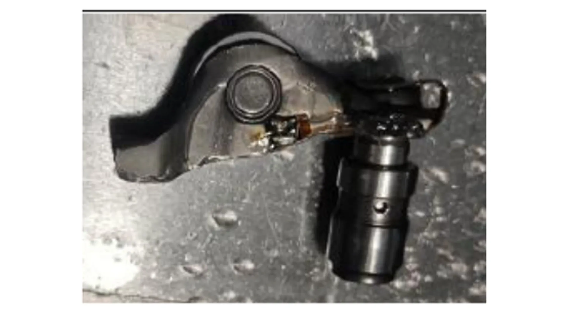
Figure 10 Stain gage to measure force on rock arm
In order to check the real margin of contact loss,the engine is run at 7 000 r/min additionally. The measured force sees Figure 11.
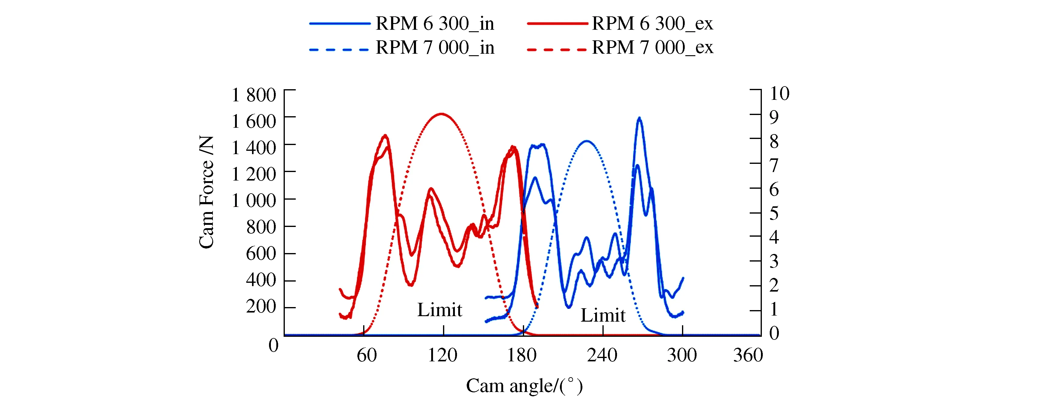
Figure 11 Spring margin
It is further proved again that contact loss is easier to happen on intake side. Actually,at 7 000 r/min,minimum force among negative acceleration range is 380 N on exhaust and the related value is only 202 N on intake side. Only negative acceleration range is chosen for evaluation of contact loss is because the contact loss always happens in this range. Current application requires 250 N force on cam as reservation against the deviation factors in the engine whole life. It is clear that intake spring at 7 000 r/min can′t meet this point. And at over speed of current application,the force on intake side already near to the limit,which has same conclusion with safety margin estimation through measured acceleration before.
5 Summary
Around the valve train dynamic behavior,the spring force is carefully chosen to meet requirement of application and to reduce friction as much as possible. Simulation and verification test are done for the optimum design to check the design further. At the whole phase from preliminary definition of key parameter to final choice,the production and cost are always the facets to be thought. The final design options are the balancing point after considering all facets including thermodynamic,dynamic behavior,package,production and cost.
Spring margin force is used to prevent abnormal valve opening and contact loss. More information is gotten through simulation and measurement,less margin can be kept for unknown extreme condition. Because less margin means lower friction loss and eventual CO2emission,the pursue to less margin will be endless target for designer though we have to sacrifice somewhat for cost reason.
