InaudibIe Sound Covert ChanneI with Anti-Jamming CapabiIity: Attacks vs.Countermeasure
2023-01-13XiaoHangWangShouBinLiYingTaoJiangAmitKumarSinghBiYunMaLeTianHuangMeiYangFenGuo
Xiao-Hang Wang | Shou-Bin Li | Ying-Tao Jiang | Amit Kumar Singh | Bi-Yun Ma | Le-Tian Huang | Mei Yang | Fen Guo*
Abstract—When an inaudible sound covert channel (ISCC) attack is launched inside a computer system,sensitive data are converted to inaudible sound waves and then transmitted.The receiver at the other end picks up the sound signal,from which the original sensitive data can be recovered.As a forceful countermeasure against the ISCC attack,strong noise can be used to jam the channel and literally shut down any possible sound data transmission.In this paper,enhanced ISCC is proposed,whose transmission frequency can be dynamically changed.Essentially,if the transmitter detects that the covert channel is being jammed,the transmitter and receiver both will switch to another available frequency and re-establish their communications,following the proposed communications protocol.Experimental results show that the proposed enhanced ISCC can remain connected even in the presence of a strong jamming noise source.Correspondingly,a detection method based on frequency scanning is proposed to help to combat such an anti-jamming sound channel.With the proposed countermeasure,the bit error rate (BER) of the data communications over enhanced ISCC soars to more than 48%,essentially shutting down the data transmission,and thus neutralizing the security threat.
1.Introduction
Among many serious security vulnerabilities facing industrial and consumer use of near-field communications technologies,covert channels can be particularly hard to be detected and thwarted due to their stealthy nature.Various covert channels can be built by exploring many different types of physical media,including,but not limited to,heat,light,and sounds.The sounds that fall into a special frequency range (>18 kHz)[1]cannot be heard by human ears and a channel thus built is named as “inaudible sound covert channel (ISCC)”.There have been a number of successful implementations of ISCCs built by commercially available hardware[2].For example,an inaudible covert channel can be established by employing the microphone (available in literally every laptop computer and smartphone nowadays) as the receiver and the speaker as the audio transmitter.
One possible way to combat ISCC is through noise jamming,as illustrated in Fig.1.A jammer,which can be a mobile phone or a computer,continuously monitors a channel occupying a specific communications frequency band.If the jammer finds that the signal exceeds a preset threshold,it can conclude a covert channel attack is occurring.In order to block the communications over the covert channel,it sends strong noise over the same bandwidth as the sound signal.As a result,the receiver experiences a high bit error rate (BER) that the data transmission is severely crippled or even becomes entirely impossible.
Although jamming can effectively block the data transmission in an inaudible covert channel,an anti-jamming technique,referred to as the adaptive sound frequency selection,can be applied to make the channel much more resilient to jamming noise.Fig.2 (a) shows the process of an anti-jamming covert channel.Data are transmitted by binary frequency shift keying (FSK) that uses bits in 18 kHz and 19 kHz to represent the states of “0” and “1”.As a jammer also sends strong noise with a fixed transmission frequency of 18 kHz,BER of the receiver balloons.However,as shown in Fig.2 (b),if the frequencies of the covert channel transmission tune to 21 kHz for the bit “0” and 22 kHz for the bit “1”,the jamming noise,with its energy centered around the frequency band between 18 kHz and 19 kHz,will not be able to corrupt the transmitted data.
In this paper,such an enhanced covert channel with anti-jamming capability is described along with its communications protocols.In particular,an adaptive frequency selection scheme is adopted,where both the transmitter and receiver keep a list of available transmission frequencies,and they keep ploughing the list until they both tune to the same frequency to establish a connection.In the literature,there are a few protocols proposed to help the covert channel recover from being jammed[3],[4].In [3],a network covert channel used the timing of packets for encoding,and in [4] the covert channel set up via audio files and the protocol was used to manipulate the data inside the audio files.Different from them,our paper targets a covert channel that uses the sound as the communications medium and transmits data wirelessly.
To combat an enhanced covert channel with anti-jamming capability,we subsequently propose a countermeasure using a frequency scanning-based detection method.First,a detector constantly monitors the frequency domain to check whether there is an attack or not.Once an attack is discovered,the noise with the same frequency is emitted to jam the current transmission channel.With a high scanning speed,the detection and jamming can track down any frequency change,and correspondingly,continue to block any data traffic over the covert channel,as the case shown in Fig.2 (c).
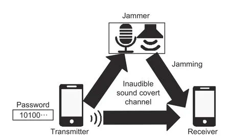
Fig.1.Illustration of ISCC that is influenced by a jammer.
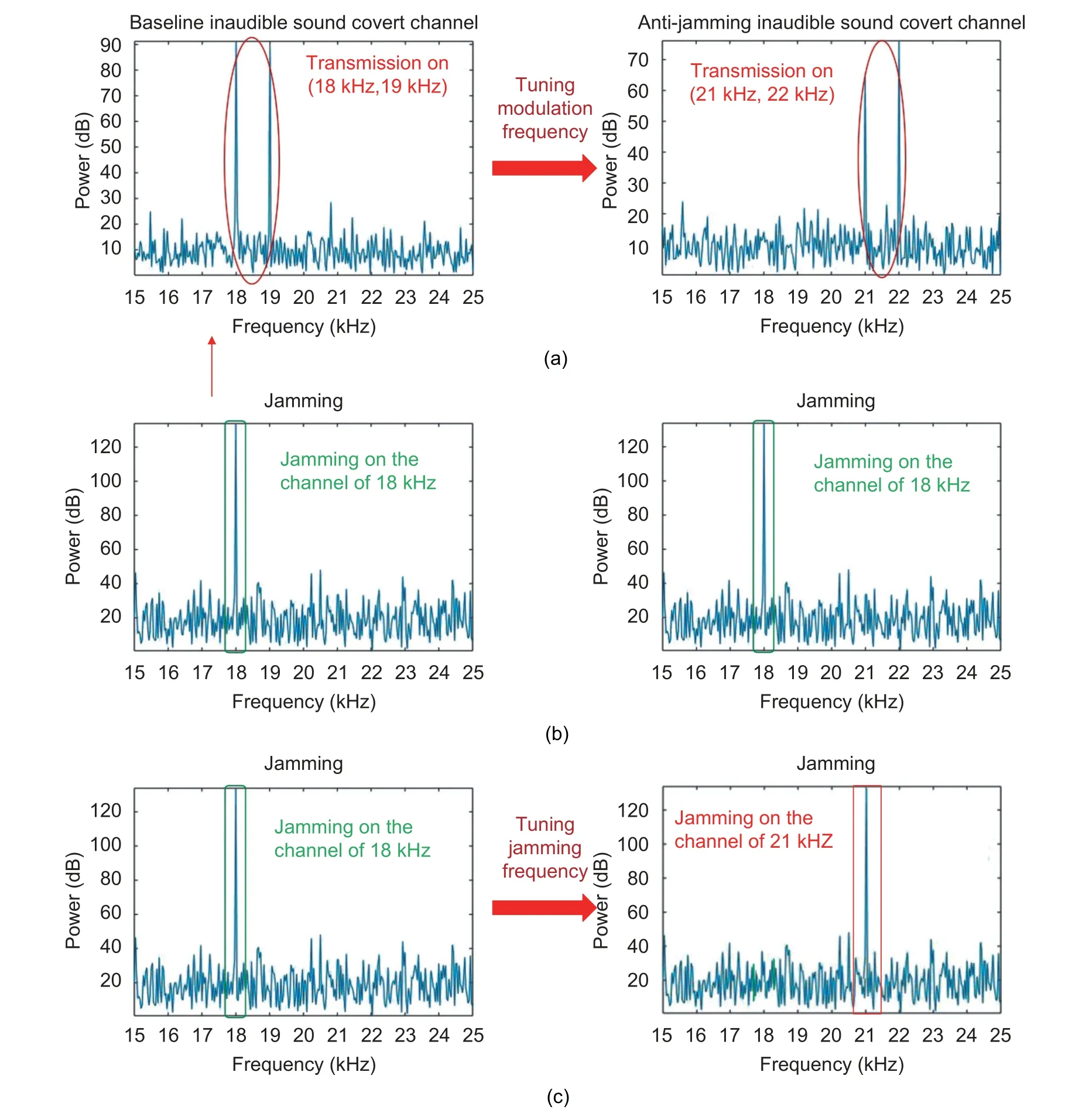
Fig.2.Illustration of the proposed method: (a) tuning modulation frequency to avoid the channel being jammed,(b) jamming noise,and (c) jammer successfully blocks the channel by tracking the frequency of ISCC.
Experimental results confirm that an enhanced attack is able to achieve BER as low as 10% with a fixed frequency jammer,leaving the attacker with a reasonably good channel for a dangerously sustained attack.However,with the proposed countermeasure,the enhanced attack will experience a very high BER value,up to 48%,which literally shuts down meaningful covert communications.
Although baseline ISCC was already studied in the literature,noise jamming is not considered against this covert channel.In this paper,an enhanced covert channel is proposed to avoid being jammed,which poses a severe threat to computer systems,followed by a countermeasure to combat it.
The remainder of the paper is organized as follows.Section 2 reviews the related work,and Section 3 introduces baseline ISCC.An enhanced sound covert channel with anti-jamming capability is detailed in Section 4.We propose a countermeasure to fight against such an enhanced sound covert channel in Section 5,and Section 6 presents the experimental results.Finally,Section 7 concludes the paper.
2.ReIated Works
Various communications media,including heat[5]-[7],cache timing[8]-[12],light[13]-[16],and infrared light[17],have found their use in forming covert channels for data communications.Compared with a sound covert channel,a heat covert channel runs a frequency far lower than that of a sound channel,resulting in its transmission throughput typically being much lower than that of its sound counterpart.The light-based covert channel is limited in its use,since the travel of light signals can be easily blocked by the obstacles between the transmitter and receiver.
Unlike an infrared light-based channel that needs special devices (the infrared camera or sensor) to receive signals,a sound covert channel can be easily established using microphones which are readily available in most smartphones and laptops.For embedded systems,the ISCC attack is found to cause a lot of damages[1],particularly when the covert channel involves inaudible sound.In [18],it was demonstrated that ISCC is able to hijack smartphones.
2.1.Sound Covert ChanneI Structure
Acoustic communications over a sound covert channel occur at three layers: The physical layer,data link layer,and application layer.
In the physical layer,various sound players and receivers have been adopted for different purposes.For example,for underwater acoustic communications,transducers and hydrophones are used as the sound player and receiver[19],while in air-gapped systems,speakers and microphones are typically used.In addition to hardware devices,acoustic communications over a sound covert channel can take advantage of many different digital modulation methods[19]-[21],including on-off keying (OOK),binary frequency shift keying (2FSK),binary phase shift keying (2PSK),and orthogonal frequency division multiplexing (OFDM).
At the data link layer of a sound-based communications system,various communications protocols are available to set up communications sessions,and most of them rely on some form of handshaking.
In the application layer,acoustic communications systems can be used for different purposes and application scenarios.For instance,acoustic signals can enable data to be transmitted underwater[19]or over the air[20],[22],[23],can be used to build ISCC[21],[24]-[26],and can be used to hijack mobile computing systems[18],[27].
Following this three-layer model,we define a baseline sound covert channel that relies on a requestacknowledgment-based communications protocol[1].The transmitter initiates data transmission by sending a request packet REQ towards the receiver,and the receiver,upon receiving it,replies with an acknowledgment packet ACK to establish a transmission.Once a data transmission session starts,data can flow from the transmitter to the receiver until the transmitter sends a terminate packet TER to the receiver to the session.
During the transmission,the transmitted data (baseband) are modulated and emitted as sound signals.The receiver filters out the noise,de-modulates the signal,and finally recovers the original data.
The entire baseline sound covert channel is shown in Fig.3,and its protocol details are provided in Section 3.
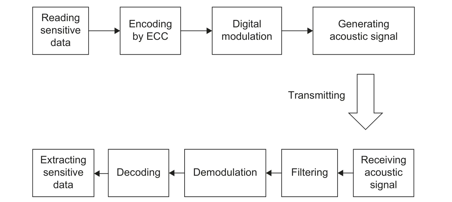
Fig.3.Baseline sound covert channel.
2.2.Anti-Jamming Using Frequency Hopping Spectrum Spreading (FHSS)
Using a jammer,ISCC can be countered by jamming it.A jammer is referred to as a fixed-frequency jammer,as it emits the noise that spans a fixed narrow frequency band.A full-band jammer,on the other hand,emits the jamming noise that spans the entire spectrum,but with very high power consumption.
Jammer-enabled jamming can be an effective means to thwart a sound covert channel.To make the sound covert channel more resilient to jamming,various anti-jamming techniques have been adopted.These techniques have found roots in wireless communications.One such technique is FHSS,which has a long history of being used to avoid jamming or increase the bandwidth utilization rate[2].In FHSS,the transmitter and receiver change the transmission frequency during the transmission following a specific frequency hopping pattern.
One challenge of the conventional FHSS technologies[28]is their implementation and synchronization costs.To synchronize the FHSS transmitter and the receiver,either a dedicated channel is used to transmit the control message (e.g.,the next carrier frequency to be used),or the synchronization signals have to be embedded into the transmission data over the same channel.In fact,conventional FHSS methods can fail the entire transmission,when the channel for transmitting the control messages is jammed.In addition,synchronization in FHSS for anti-jamming sound covert channels often incurs high computation overhead.Such high implementation and synchronization costs in FHSS make it particularly challenging to keep the covert channel stealthy,as the channel prefers to be lightweight and bear a low implementation cost so that little traces are left for the scrutinizer (e.g.,a security-aware operating system that is able to check process anomalies) to detect its existence.
3.BaseIine ISCC
As shown in Fig.3,ISCC has two components: The transmitter and receiver.Their functionalities and signaling are described here.
3.1.Transmitter
A transmitter can be a speaker of a laptop or a phone that generates and emits sound signals following a process defined below.
• The transmitter first grabs the data (e.g.,password) to be transmitted.
• It encodes the data with errors and packetizes them with added error control codes (ECCs).
• The data packet is modulated by a carrier frequency (typically at a frequency between 18 kHz and 20 kHz).Either amplitude shift keying (ASK) or frequency shift keying (FSK) can be used for modulation,and the latter is used in this paper.In FSK,the bit “0” is encoded as a lower frequency sound signal (e.g.,18 kHz),and “1” is encoded as a higher frequency sound signal (e.g.,19 kHz).
The signal to be transmitted,f(t),is thus given as,

andtis time,andω1andω2are angular frequencies.
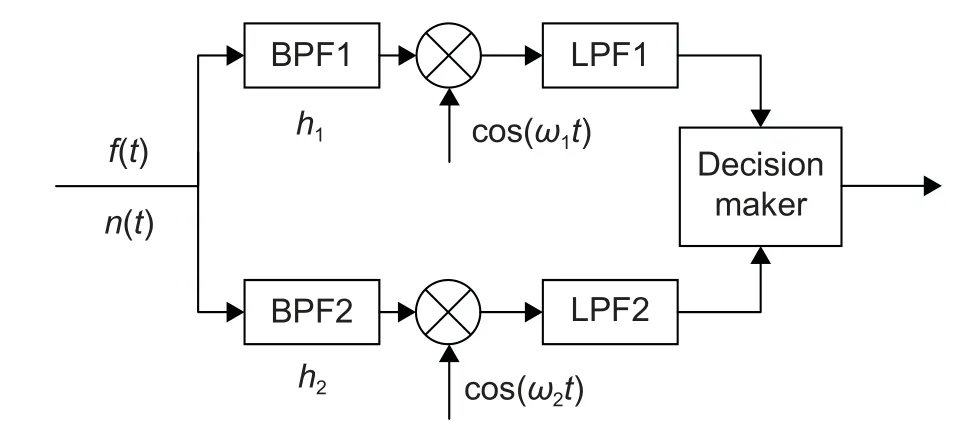
Fig.4.General receiver structure.
3.2.Receiver
The receiver picks up the sound signal coming to its receiving device,such as a microphone.The front end of the receiver has two disjoint paths (see Fig.4),one for the extraction of the high-frequency componenth1of the signal received,and the other for the low-frequency componenth2.At each path,the signal passes through a band-pass filter (BPF)with the center frequency ofhiand the bandwidth ofBi,followed by a mixer with the oscillation frequency ofwi,wherei=1 or 2.After passing the mixer,the signal proceeds to a low-pass filter (LPF).The outputs from the two signal paths converge at the decision-making module,which decides whether the received bit is “1” or “0”.Specifically,the receiver works as follows:
1) The sound signal is recorded and saved as a wave file.
2) The band-pass filters (BPF1 and BPF2) are used to filter out the signals according to the carrier frequencies.
The received signal,s(t),is written as

wheref(t) is the actual signal defined in (1),andn(t) is the noise.
The output of BPF1 is given as

whereα1(t) is the output noise of BPF1.
In the same token,the output of BPF2 is given as

whereα2(t) is the output noise of BPF2.
The signal output from the respective mixer is given as,

The output signal of the mixer gets filtered by passing through LPF with a cut-off frequency ofhi(i=1,2).The output of LPF,s0,i(t),is given as

wherenc,i(t) is the output noise of LPFi(i=1,2)[29].
The decision maker makes a hard decision by comparing the signal amplitudes from the two signal paths.If the amplitude of the upper path is higher than that of the lower path,the received bit is deemed as bit “1”;otherwise,bit “0”.
The transmitter modulates the data into a bitstream as a waveform audio file format (.wav) file.The transmitter then drives its speaker to emit the signal.On the receiver side,it records the audio signal from its microphone and demodulates it to extract the original sensitive data.
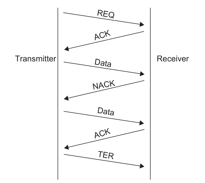
Fig.5.Message flow of the communications protocol of the baseline channel.
3.3.Communications ProtocoI
As shown in Fig.5,the transmitter sends a REQ packet to initiate a data transfer,and the receiver responds with an ACK packet to establish a communications session.Upon receiving the ACK packet,the transmitter sends its first data packet to the receiver.If the receiver does not receive the data packet,it sends an NACK packet back to the transmitter to request to resend.If the receiver does receive the data,it needs to respond to the sender with an ACK packet.To end the communications session,a TER packet is sent.
4.Anti-Jamming Sound Covert ChanneI
4.1.Communications ProtocoI to Support ModuIation Frequency Tuning
Assume that the setF={f0,f1,…,fn} contains all the available frequencies for a sound covert channel.The transmission frequencies of the FSK signalfifall into the range of (h1,h2),withh1andh2being the highest and lowest available frequencies,respectively.

whereh0is the lowest frequency inF,and the frequency goes byaitimes of the increments of ∆h.
The communications protocol works as follows.Initially,the transmitter initializes the transmission by sending a REQ (f0,NULL) packet,indicating that the transmitter operates on the frequencyf0(the first available frequency,also the lowest).The receiver responds by sending an ACK (f0,NULL) packet to confirm that the following packets can be transmitted on the frequencyf0.Since both the receiver and the transmitter agree to operate on the same frequency,f0,a communications session is established.
For every packet sent from the transmitter to the receiver,the receiver,upon receiving it,has to send an acknowledgment back to the transmitter.Once the communications are over,the transmitter sends a TER packet to terminate the communications.
During the transmission,the transmitter,after sending a packet,waits for the receiver’s ACK or NACK.Upon receiving ACK (fi,NULL),it starts to transmit the next data packet (as shown in Table 1,Algorithm 1,lines 5 to 9).But if the transmitter receives NACK (fi,NULL),it resends the last packet (Algorithm 1,lines 27 and 28).If the receiver receives more than one NACK packet,it needs to switch to a different transmission frequency by going through the modulation frequency tuning process (Algorithm 1,lines 11 to 25).And in Table 1,AFQ (fi,fj) means the dynamic frequency tuning request and AFA (fi,fj) means the dynamic frequency tuning acknowledgment.
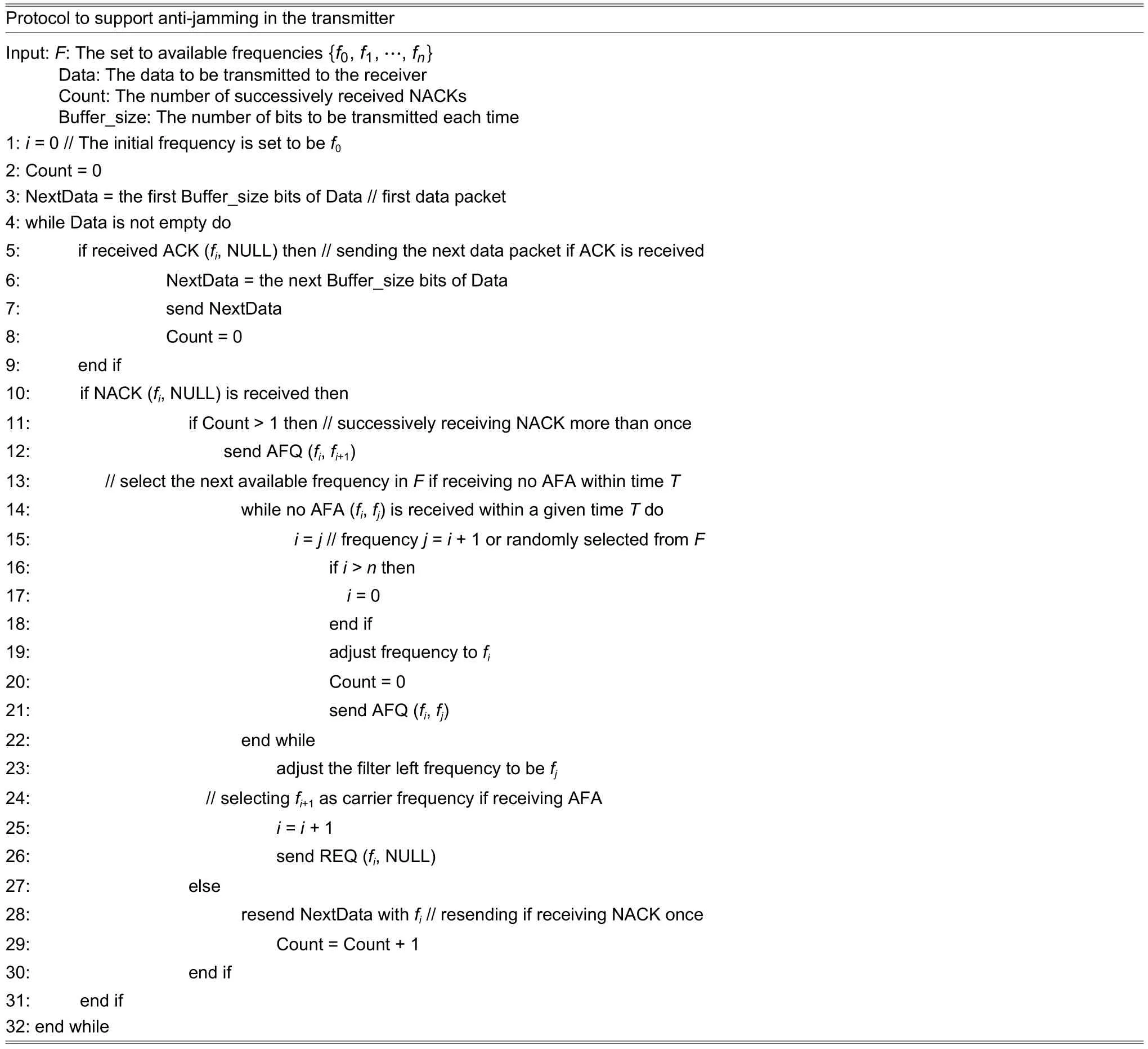
Table 1: Algorithm1
On the receiver end,if it finds BER of the received packets exceeds the thresholdT1,it sends NACK(fi,NULL) (as shown in Table 2,Algorithm 2,lines 14 and 15) towards the transmitter.Once NACK is received by the transmitter,it resends the last packet.If BER of the resent packet is still higher thanT1,the receiver sends another NACK (fi,NULL).Upon receiving the second NACK,the transmitter starts to change its transmission frequency following a procedure as follows.

Table 2: Algorithm 2
Step 1: Assume currently the transmission uses the frequencyfi.If the transmitter needs the receiver to switch to the frequencyfj(frequencyfj=fi+1or randomly selected fromF),it sends a dynamic frequency tuning request AFQ (fi,fj) to the receiver(Algorithm 1,line 12).
Step 2: After the receiver receives AFQ (fi,fj),it adjusts its filter center frequency to befjand replies the transmitter with a dynamic frequency tuning acknowledgment AFA (fi,fj) (Algorithm 2,lines 22 to 25).
Step 3: After the transmitter receives AFA (fi,fj),its carrier frequency switches tofj(Algorithm 1,lines 23 and 24).
Step 4: The transmitter reinitializes the transmission by sending new REQ (fj,NULL).The receiver then sends back ACK (fj,NULL).Now the communications session between the transmitter and receiver is resumed atfj.
In the worst case,the jamming noise may cause some of the packets incorrectly decoded.To solve this problem,the transmitter and receiver set up a timerTtranandTrecoperating atfi,respectively.The threshold forTtranandTrecis set toT.If the communications are not terminated,but the receiver receives no packets atfiafterTrec(Algorithm 2,lines 3 to 8) expires,it iteratively runs throughfi+1,fi+2,…,fnto see if there is a frequency tuning request.
The transmitter waits until its timerTtranis out,and sends AFQ (fi+1,fi+2) using the frequencyfi+1,after which the timer is reset.If the transmitter cannot receive an ACK packet whenTtranexpires,it continues to send AFQ (fi+2,fi+3) using the frequencyfi+3,while resettingTtran.Both the transmitter and receiver keep monitoring or sending requests at the next available frequency until they are synchronized at the frequencyfjto resume their communications.
In this proposed protocol,the following packets are needed,Data,ACK,NACK,REQ,AFQ,and AFA,and their formats are shown in Fig.6,where:
Preamble: A bit pattern that contains consecutive“1”s and “0”s to indicate the packet begins.
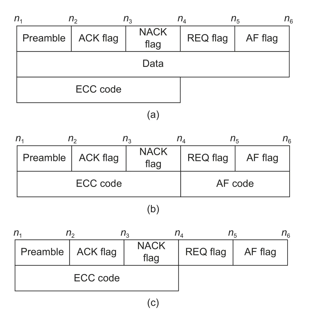
Fig.6.Packet formats of (a) Data,(b) AFQ and AFA,and(c) ACK,NACK,and REQ.
ACK flag: 1 bit.The flag is set as “1” if it is an ACK/AFA packet,or reset as “0” otherwise.
AF flag: 1 bit.The flag is set as “1” if it is an AFQ/AFA packet,or reset as “0” otherwise.
Data: This is the actual data payload.
AF code: Binary representation of the corresponding frequency.
ECC code: It is used to defend against data corruption.
4.2.Transmitter ModuIe
The transmitter operates on the frequencyfi.The frequency tuning process at the transmitter side is triggered,when the transmitter receives AFA (fi,fj),or the transmitter receives no acknowledgment packets withinTtran.
The transmitter receives AFA (fi,fj),after it sends AFQ (fi,fi+1) to the receiver and adjusts its carrier frequency tofi+1.If it does not receive AFA (fi,fj) withinTtran,it keeps sending AFQ(fi+1,fi+2),AFQ(fi+2,fi+3),…continuously until it gets a reply from the receiver.

Fig.7.Transmitter of the anti-jamming covert channel tunes frequency.
4.3.Receiver ModuIe
The receiver operates on the frequencyfi(see Fig.7).It needs to tune the center frequency of its filter in two scenarios,as shown in Fig.8:
1) When the transmitter receives AFQ (fi,fj) from the transmitter,the receiver adjusts the center frequency of its filter to befi+1and replies the transmitter with AFA (fi,fj).
2) If the transmitter does not receive REQ (fj,NULL) after it tunes its frequency withinT,the receiver iteratively tunes the center frequency of the filter tofi+2,fi+3,…,until it receives a request packet.
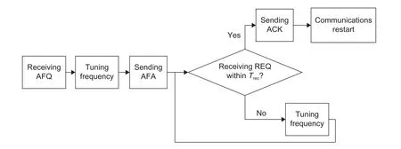
Fig.8.Receiver of the anti-jamming covert channel tunes frequency.
The data flow of anti-jamming ISCC is shown in Fig.9.Assume the covert channel is usingfito transmit packets and the receiver detects that jamming is in effect.It sends NACK (fi,NULL) to the transmitter,which demands the transmitter to resend the data packet previously sent.If the receiver detects the jamming is persistent,it will send NACK (fi,NULL) to the transmitter again.The transmitter then sends AFQ(fi,fj) to the receiver to initiate another round of frequency tuning.The receiver replies by sending AFA (fi,fj) toward the transmitter,and both need to switch tofj.Then,the transmitter sends REQ(fj,NULL) and the receiver responds with ACK(fj,NULL),which resumes the communications.
The data and control packets can work at two separate channels,such that when the data channel is jammed,the control packets can still be delivered.Both channels can tune their operation frequencies.
5.Countermeasure
As the intuitive countermeasure in response to an enhanced sound covert channel described in the previous section,full-band jamming,whose bandwidth of the jamming noise covers the entire frequency bandFof the audio covert channel,can be applied.However,this indiscriminate approach comes with excessive power consumption.Instead,a lightweight countermeasure,which is much more power efficient,is proposed.
As shown in Fig.10,the proposed countermeasure scheme involves a detector and a jammer.The detector is able to let BPF’s center frequencyfdbe tuned betweenJ1andJ2.In practice,18 kHz ≤J1<J2≤ 22 kHz.Once a possible covert channel signal centered aroundfdis detected,the jamming noise withfdis emitted to jam the channel and block any data transmission.
5.1.Detector
The detector performs the following steps.
Step 1.Scanning in the frequency domain
The detector continuously picks up the audio signals using an acoustic sensor,such as a microphone.BPF with the center frequencyfiand the bandwidth of 1 kHz is used to filter out the audio signals outside the spectrum (as shown in Table 3:Algorithm 3,line 3).The center frequencyfdof BPF increases in a stepwise manner,that is,fi(n)=fi(n-1)+∆f(Algorithm 3,line 7),wherefd(n) andfd(n-1) are the center frequencies at thenth and (n-1)th steps of the scanning.The scanning will cycle through the entire frequency range of [J1,J2].
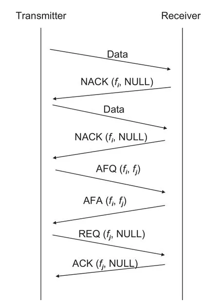
Fig.9.Message flow of an anti-jamming covert channel.
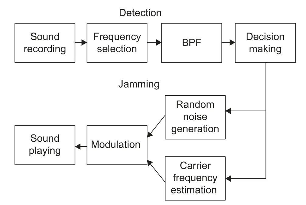
Fig.10.Structure of the jammer.
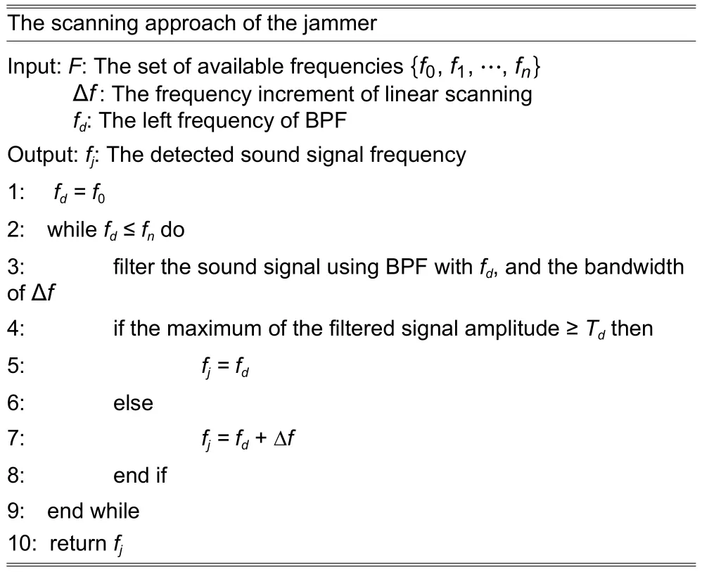
Table 3: Algorithm 3
Step 2.Decision making
If the amplitude of the output signal from BPF exceeds the thresholdTd(Algorithm 3,lines 4 to 5),it is deemed that a covert channel is present.If a covert channel is detected,the jammer emits the noise spanning the same frequency used by the covert channel.
5.2.Jammer
Once the sound covert channel is detected,the jammer starts the jamming process,which has the following steps.
Step 1.Random noise generation
Once ISCC is detected,a pulse train (i.e.,a sequence of consecutive “1”s) is generated to jam the covert channel.This sequencesj(t) can be expressed as

whereTjis the period of one bit (symbol width),nis the random natural number,andgj(t) is the baseband pulse waveform with a duration ofTj.
Step 2.Modulation
The noise sequencesj(t) is modulated for transmission as the sound signal with the carrier frequencyfj.The sound signalej(t) is thus

wherec(t) is the carrier signal.
Step 3.Sound playing
The noise is played by the jammer’s audio device (e.g.,a speaker).The noise at the frequencyfjthus causes the receiver’s decoder to fail to decode the signal received.
6.Experiment and EvaIuation
6.1.Experiment Setup
Three laptop computers are used to run the experiments,one serving as the transmitter,one as the receiver,and the third as the jammer.All three have the same configurations,as tabulated in Table 4.The laptop model is Hasee Z6-KP7S1.In our experiments,we compare the transmission BER and throughput measured in bit per second (bps).Table 5 summarizes all the parameters as described in Sections 3,4,and 5.
In the experiments,the transmitter and receiver operate with four frequencies,and their respective codes are shown in Table 6,which are the AF code field of the data packets.

Table 4: Configuration of the three laptops in experiments
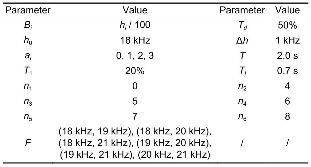
Table 5: Detailed parameters

Table 6: A 2-bit code represents a frequency in a data packet
The transmitter sets up its timerTtran,and the receiver sets up its timerTrec.The threshold for bothTtranandTrecis set to beT.IfTis too short,the covert channel adjusts the frequency frequently,which reduces the throughput.IfTis too long,when the covert channel is seriously jammed,it cannot adjust the transmission frequency quickly enough,which can adversely impact the transmission throughput.Fig.11 shows how the throughput varies with the value ofT.From Fig.11,it can be seen that the throughput of the anti-jamming sound covert channel reaches its highest performance withT=2 s.So,in the following experiment,we setTtranandTrecto be 2 s.
6.2.EvaIuating Anti-Jamming Covert ChanneI
A.Evaluating with Different Distances
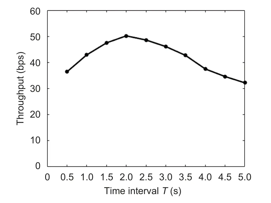
Fig.11.Throughput vs.T.
In this set of experiments,the distance between the transmitter and receiver varies from 0.5 m to 1.0 m,1.5 m,and 2.0 m.The jammer works at a frequency randomly chosen from the band given in[18 kHz,22 kHz].The throughput thus obtained is normalized with respect to that of the proposed anti-jamming covert channel.
Fig.12 compares the proposed anti-jamming covert channel against the baseline covert channel[1]by varying the communications distance with a fixed jammer working at a frequency randomly chosen from the band that falls into [18 kHz,22 kHz].As shown in Fig.12 (a),with a distance of 0.5 m,the proposed anti-jamming covert channel can reduce BER by 72.9% over the baseline covert channel.The proposed anti-jamming covert channel shows its BER 67.2% lower than the baseline covert channel,as the distance stretches to 2.0 m.The drop of BER with the increase of the transmission distance is due to the decay of the sound signal as the transmitter and receiver are farther apart.As the proposed covert channel can change its transmission frequency,it is less impacted by jamming,and its BER is quite low,largely regardless of the transmission distance.
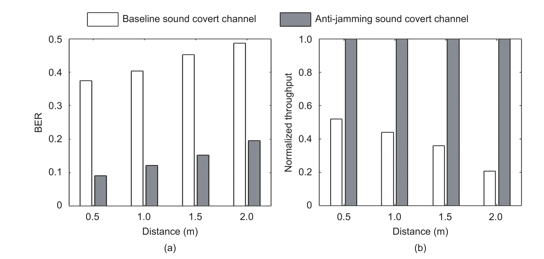
Fig.12.BER and throughput comparison when the transmitter and receiver are at different distances: (a) BER and(b) throughput (normalized).
As shown in Fig.12 (b),the throughput of the anti-jamming covert channel is higher than that of the baseline covert channel.At a long distance,in this case,the transmitter and receiver are 2.0 m apart,which shows that the throughput of the proposed covert channel is 5 times of that of the baseline covert channel.
B.Evaluating with Different Signal Noise Ratios (SNRs)
In this set of experiments,SNR varies from 10 dB,20 dB,30 dB,40 dB,50 dB,60 dB,to 70 dB by changing the jamming noise power.The jammer works at a frequency randomly chosen from the band of[18 kHz,22 kHz].The throughput is normalized with respect to that of the anti-jamming covert channel.
In Fig.13 (a),with SNR at 10 dB,the proposed anti-jamming covert channel can reduce BER by 63.2%over the baseline covert channel[1].The proposed anti-jamming covert channel can reduce BER by 77.1%over the baseline covert channel,as SNR increases to 70 dB.With higher SNR,the noise impact becomes less significant.In sharp contrast,the baseline covert channel without anti-jamming capability can be easily compromised by the jammer with its strong jamming noise.Since the proposed covert channel can change its transmission frequency when it senses the jamming,it immediately dodges the jamming noise to deliver a high throughput performance.
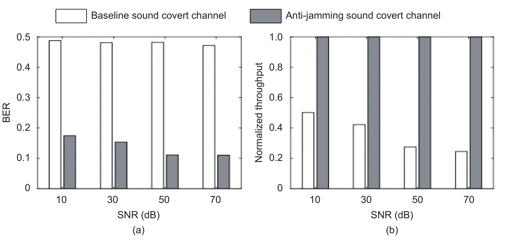
Fig.13.BER and throughput comparison with different SNRs: (a) BER and (b) throughput (normalized).
As shown in Fig.13 (b),the throughput of the anti-jamming covert channel is higher than that of the baseline covert channel.With 70-dB SNR,the throughput of the proposed covert channel is 4 times of that of the baseline covert channel.This is because the proposed anti-jamming covert channel is able to reduce transmission BER,which can be translated into the suppression of time,otherwise data retransmission is needed.
C.Comparison with the Existing Audio Covert Channels
In this set of experiments,we compare the proposed anti-jamming covert channel with four existing audio covert channels,the baseline sound covert channel[1],the covert acoustical mesh network[20]which is established by multi-hop communications between different sound covert channel participants,and two other channels that incorporate FHSS.The latter two channels are referred to as FHSS-A (a channel that uses an independent channel at 18 kHz for synchronization)[28],and FHSS-B (conventional FHSS using the same communications channel of data transmission for synchronization)[2],respectively.These schemes are compared when they are exposed to fixed-frequency jamming noise with different noise power levels.Here the normalized jamming noise power is defined as the ratio of the jammer’s noise power to the audio covert channel’s communications signal power.
As shown in Fig.14,BER of FHSS-A is much higher than that of the proposed sound covert channel.The reason is that,once the channel for synchronization is jammed,the whole communications will be shut down completely.Since FHSS-B uses the same communications channel for synchronization,when the frequency of jamming noise matches the communications channel’s frequency,both the transmission and synchronization will be blocked by the fixed frequency jamming,making BER of FHSS-B significantly higher than that of the proposed audio covert channel.
When the power of the jamming noise equals that of the sound covert channel signal,BER of the baseline sound covert channel is as high as 49%,while BER of the proposed audio covert channel is only about 10%.The reason is that the jammer can detect the frequency of the baseline sound covert channel and inject the jamming noise in the same frequency,which drags the receiver of the baseline sound covert channel to make incorrect decoding decisions.BER of the covert network in [19] is lower than the baseline sound covert channel,but much higher than that of the proposed sound covert channel,especially when the power of jamming noise equals that of the sound covert channel signal,BER of the covert network in [19] is as high as 46%,while BER of the proposed scheme is only 10%.Because when the jamming noise is strong,the transmission in the covert network in [19] is completely blocked.In sharp contrast,the proposed anti-jamming covert channel can change the frequency of communications dynamically and can finally synchronize with the proposed communications protocol even under strong jamming noise,so its BER being the lowest among all the channels.
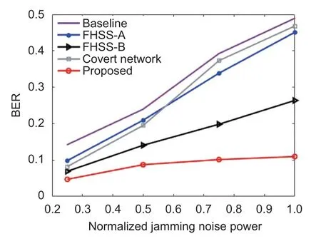
Fig.14.BER comparison by varying the power of jamming noise.
6.3.EvaIuating Proposed Countermeasure
A.Evaluating the Detection Unit
In this set of experiments,the scanning speed of a jammer (given as the number of center frequency changes per second),which varies from 1 time/s to 10 times/s,is examined to determine how it is related to detection efficiency against the proposed enhanced ISCC.
From Fig.15 (a),it can be seen that,as the scanning speed increases,BER of the proposed anti-jamming covert channel rapidly increases.With the scanning speed of the jammer at 1 time/s,BER is only 9.5%;while at the scanning speed of 10 times/s,BER jumps to 47.3%.Because with the increase of the jammer scanning speed,there is an increased probability that the jammer is able to find and thus jams the transmission.As the scanning speed reaches 10 times/s,the detector is able to track the covert channel in a more fine-grained manner,and correspondingly,BER skyrockets.
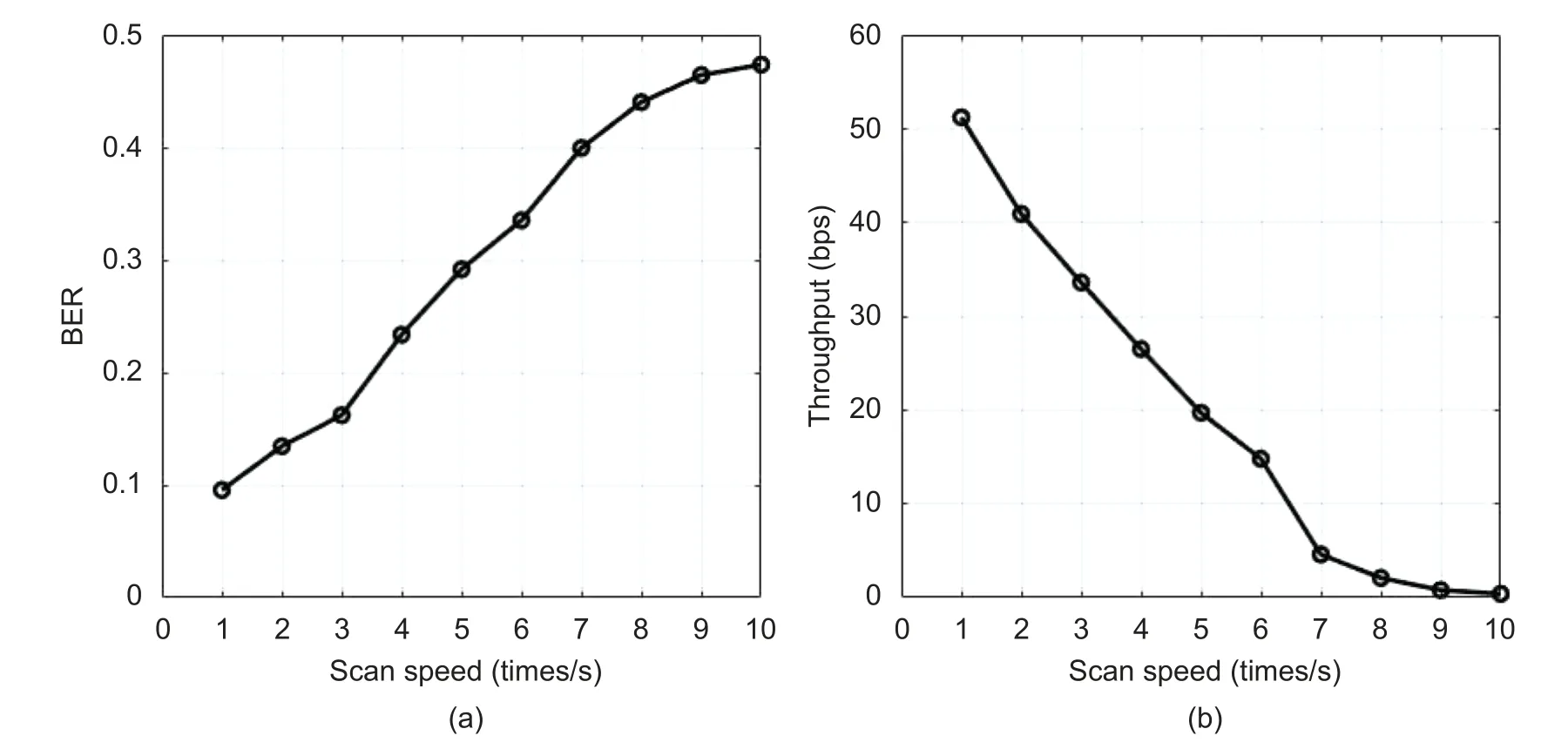
Fig.15.BER and throughput under different scanning speeds of the jammer: (a) BER and (b) throughput.
Also shown in Fig.15 (b),as the scanning speed gets faster,the throughput of the proposed anti-jamming covert channel decreases.When the scanning speed is 1 time/s,the effective throughput (valid bits received by the receiver per second) of the proposed covert channel is about 50 bps.In sharp contrast,as the scanning speed increases to 10 times/s,the throughput of the proposed covert channel drops to nearly 0.In this case,the covert channel continues to change its frequency all the time,and therefore,there will be no meaningful data transfers.
B.Evaluating Countermeasure
In this set of experiments,we compare the following four countermeasures against the proposed anti-jamming ISCC:
1) The first one is a fixed-frequency “narrow-band” jamming with a center frequency of 19 kHz and a bandwidth of 3 kHz.
2) The second one adopts the proposed countermeasure,which can track the communications frequency of ISCC and send jamming noise as detailed in Section 5,with a bandwidth of 1 kHz.
3) The third one is “multi-tone” jamming together with the proposed detection approach.Multi-tone jamming tracks not only the transmission frequency,but also the receiving frequency.Both frequencies of the FSK signal are detected,and the noise at these two frequencies is emitted,with a bandwidth of 1 kHz.
4) The last one is “full-band” jamming,whose bandwidth stretches to the entire communications spectrum,from 18 kHz to 22 kHz.
The experiments are performed in quiet (e.g.,a room without background noise and people),normal(e.g.,a research lab),and noisy environments (e.g.,the public area of a university campus).
Fig.16 shows BER and the power consumption of the anti-jamming covert channel when the four countermeasures are separately applied.For each of the four countermeasures,its power is determined as the integral of the power spectrum density across the entire frequency band (from 18 kHz to 22 kHz) of the jamming noise,and the result is normalized with respect to that of the full-band countermeasure.It can be seen that,from Fig.16,for each of the countermeasures,the jamming effects in different environments are similar.This is because the covert channel runs at a frequency (over 18 kHz) that is typically higher than the environmental noise,making the covert channel less impacted by the environmental noise.The jamming effect of the fixed-frequency narrow-band countermeasure is weaker than the others,which leads to maximal BER of only about 25%.The full-band jammer can cover the whole frequency spectrum,which causes BER to reach 50%,but at a cost of high power consumption which is 5 times over that of the proposed scheme on average.On the other hand,the proposed countermeasure can achieve BER of 45% with much lower power consumption than the full-band jamming countermeasure.The multi-tone jamming can also achieve BER of 47%,which is slightly better than the proposed countermeasure,but at a high cost,i.e.,its power consumption is twice as much as that of the proposed countermeasure.As shown in Sections 3 and 5,the dual frequency FSK system uses two frequencies to carry bits “0” and “1”,and the receiver makes its decision based on the amplitudes of the signals that come with two frequencies.So even if the proposed countermeasure is a single-tone jamming approach,the receiver’s decision maker cannot give the right decision,i.e.,the proposed jamming makes the receiver always get an all-“1” bitstream.In summary,the proposed countermeasure can effectively defend against the anti-jamming covert channel with a very low cost in terms of power consumption.
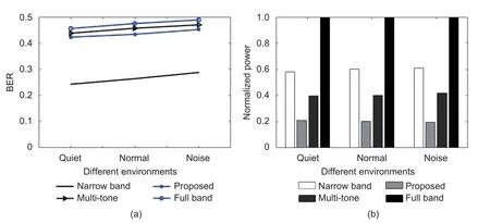
Fig.16.BER and the power consumption of the anti-jamming covert channel: (a) BER under the four countermeasures and (b) power consumption of the four countermeasures (normalized).
7.ConcIusions
In this paper,an anti-jamming enhancement for ISCC is proposed to prevent the channel from being jammed.Essentially,an enhanced covert channel relies on its transmission frequency to be dynamically changed,when a jamming noise source is found.Such enhancement will contribute to the BER reduction of the channel,which effectively increases the transmission throughput and makes the channel more robust and thus more dangerous.To combat this enhanced covert channel,a scanning-based detection method and a countermeasure are proposed.This countermeasure scheme tracks the transmission frequencies of the covert channel and accordingly emits noise occupying the same frequency band to block any data transmission.Experimental results showed that with a jammer running at a scanning speed of 10 times/s,the throughput of the proposed anti-jamming covert channel drops dramatically,as its BER rises to a remarkably high level,48%,which effectively shuts down any meaningful data communications.
DiscIosures
The authors declare no conflicts of interest.
杂志排行
Journal of Electronic Science and Technology的其它文章
- PIasma-Enhanced Atomic Layer Deposition of Amorphous Ga2O3 for SoIar-BIind Photodetection
- OrganometaIIic L-AIanine Cadmium Iodide CrystaIs for OpticaI Device Fabrication
- Redox Memristors with VoIatiIe ThreshoId Switching Behavior for Neuromorphic Computing
- Measurement and Characterization of Microwave Interaction between Integrated Distributed Feedback Laser Diode and EIectro-Absorption ModuIator
- ModeIing and SimuIation for Transient ThermaI AnaIyses Using a VoItage-in-Current Latency Insertion Method
- Direction-of-ArrivaI Method Based on Randomize-Then-Optimize Approach
