System Design Methods Respecting Feasibility Analysis for Research on Example of Vehicle Rollover Risk Estimation
2022-12-26DrIngOlenaIvanova
Dr.-Ing.Olena Ivanova
(ITK-Engineering GmbH,Stuttgart 70565,Germany)
【Abstract】In this paper,the research design approach for vehicle rollover risk estimation is mapped to the Software Platform Embedded Systems (SPES) model-based system design.Such mapping shall simplify a transition of research results into industrial development and detect the missing design information.In this example,the general differences between research and industrial design approach content are analyzed,and the generalized system design algorithm for functional concept optimization regarding technical and logical constraints is considered.It is also analyzed what design derivation steps for the functional concept in research are necessary for easier integration in industrial development and how they could be systematized.A feasibility analysis is regarding physical constraints and required accuracy is integrated into the design derivation algorithm to reduce design efforts and design iteration loop.In the analysis of the rollover risk estimation case,the necessary estimation accuracy models are provided as well.Since for the rollover case analysis,it is suggested that the verification process and system design method respecting feasibility analysis should be combined with quantitative system design parameter optimization.
Key words:Model-Based System Engineering (MBSE),Vehicle rollover risk estimation,Feasibility analysis
1 Introduction
Nowadays,the complexity of the development systems is increasing,while development time,efforts shall decrease,therefore,the reusability of the development results plays a more critical role.
Accordingly,an efficient method for system design and development is required.Several research and industrial project were established to improve system design methods[1-2],to enable them to handle system complexity and use system design information digitalisation for automated system design optimization[3-4].
Such methods shall contain:Quality criteria for the design approach;Notation∕documentation methods for a design approach;Necessary development steps and analysis for design derivation,validation&optimization workflow.Such development methods or best praxis are already established for the different industrial serial projects.
Research results are essential input information for industrial system design.Moreover,there is the following expectation of researching design results:
a.A provided system design is feasible for a bright range of exploitation and environmental condition.
b.A provided design approach is possible with available on market systems and components.
c.System design is already optimized regarding necessary algorithm steps and system complexity.
d.A design approach is documented in a way easier to transfer in serial projects and apply change management.
Analysis is constrained to one of the established serial design notation methods Software Platform Embedded Systems(SPES),which allows us to differentiate between functional algorithm,logical platform design and particular technical application,and differ between several details levels and scopes as a system of interest,a system under development and developed subsystems.
It shall be checked,how system design methods can support researchers and serial developers by design assumption validation and system design optimization.Such an approach shall also enable earlier integration of quality and safety criteria in system design[4].
In this paper,parametric mathematic model is derived for system under development from system design goals for system of interest and available system accuracy constraints via optimisation of the system accuracy budget.The received design results and steps are assigned to the SPES notation and validated in simulation and driving experiments.
2 SPES Approach for MBSE
Model-Based System Engineering (MBSE) handles all system design information as one data model,where data duplication is prevented,and design dependencies are traceable.SPES approach offers a structure for design information data model and major design derivation steps.
SPES design approach as in[1]fulfils the following quality criteria:
a.Reusability of design approach parts and its simplified transfer.
b.Applicability for automatized analysis methods due to structured design information.
c.Applicability of technical design optimization without significant changes in the functional algorithm.
d.Ability to redefine the system under development∕subsystem during design derivation or optimization.
Thereby SPES design approach answers the typical system engineering questions:
a.What kind of input information is necessary,and what kind of output information is required.
b.How the derived information shall be validated or analysed,and what quality criteria hold for information.
c.How the design information shall be derived during the development process,does any design optimization or design iterations shall be applied.
The scope of this paper is to analyse the following items,shown in Figure 1:

Figure 1.Goals and methods for system design in research
a.How the research activities differ from the industrial one and how systematic analysis and design optimization could be applied in the research field most conveniently.
b.What design documentation∕notation methods from the industrial design could be applied for the research projects and used by the further design analysis and optimization.
c.How the(partly)automatization of system design derivation and analysis could improve the final system design approach.
2.1 SPES Structure for System Design Notation
During the development process,several design iterations could occur.The design approach shall be documented in a clear structure to simplify change management.A formal notation could also enable an automated analysis and design optimization.The form of the proper notation for the system design depends on the design optimization algorithm.
However,there are some general principles,which could always be applied.
2.1.1 Problem definition and its solution
It shall be distinguished between problem definition and its solution.In the typical development process,as in[1],the requirement viewpoint specifies the problem definition.Thereby,the problem definition(requirements)on the higher details level could be linked to the design decision,which at the same time is a problem definition for the lower details level.Besides textual requirements,semiformal notation methods could also be used in problem definition,like in[5].The most convenient language for such semiformal requirements notation is Unified Modelling Language(UML),see[2].This language could also be used for design approach and architecture notation and has interfaces to the software implementation tools.Thus,UML simplifies integrating design information into the complete development process.
2.1.2 Level of concept abstraction for system design
In[1],it has differed between 3 following abstraction viewpoints:
a.The functional viewpoint specifies the functional algorithm,which could be applied for several technical realizations.For unnecessary generic information documentation prevention,some technical&logical constraints from the previous level of details shall be respected by the functional design derivation,an example of such technical constraints could be an operation principle of sensors and actuators and an example of logical constraint could be an availability of subsystems information,and interactions with other systems,etc.
b.The logical viewpoint enables integrating the functional algorithm into system design with several functionalities and responsibilities.It shall also respect a possible platform design.The functional-related logical design constraints shall be explicitly notated(e.g.,features responsibilities by distributed development).
c.A technical viewpoint specifies applying the derived functional algorithm for a concrete technical system.The functional-related technical constraints shall be explicitly notated(e.g.,available technical interfaces).
A functional concept that does not respect technical&logical limitations holds as a non-feasible one or requires other technical or logical realization.Consequently,by the derivation of functional concept for the level of the following detail,a feasibility analysis regarding functional goals,technical constraints,and logical constraints shall be applied.
2.1.3 Level of design details and design scope
The choice of the detail levels is defined chiefly for each project individually,but there are also some general terms and definitions:
a.System of Interest(SOI)describes an interaction of all related procedures for achieving functional goals.
b.A System under Development(SUD)confines relevant systems for the design approach.It might contain some transfer submodules,which shall not be changed and defined as technical constraints.
c.Submodules divide the system under development into parts to enable its distributed optimization.
The main criteria for the choice of SUD are a choice of system cut,which with fewer development efforts ensures sufficient(in some cases most significant)key performance improvement for complete SOI.
Submodule’s structure∕architecture depends on the design methods and organizational and logical constraints.
2.2 Some Quality Criteria for Functional Concept
As was defined above,the functional concept shall firstly fulfill the functional goal respecting technical and logical constraints.Therefore,required information accuracy,availability&reliability shall be defined to fulfill the functional goals.If the required information accuracy,availability&reliability could not be achieved because of the technical constraints,such functional goal holds as a non-feasible one.
2.3 SPES Design Approach Steps
Model-based design approach allows to describe design derivation as a path over SPES-matrix,shown in Figure 2.

Figure 2.MBSE design steps
Such design description is quite abstract and requires further quality gates definition of each work product(e.g.,4-functional concept for SUD).Such a design approach is applicable for a gut-known preliminary functional concept.The process shall support design iteration loops depending on the feasibility analysis results.
Feasibility analysis of functional concept regarding technical constraints which respects information accuracy takes sufficient manual efforts because of:
a.The complexity of interval computations.
b.Possible accuracy dependencies for further system states.
c.Difficulty of optimal∕feasible system accuracy budget choice.
3 Vehicle Rollover Risk Detection
This paper analyses the design method using the example of a Ph.D.thesis[6]for vehicle rollover risk estimation.The scope of the research is rollover risk estimation and its prediction for other autonomous systems.In addition,another design goal is to prevent unnecessary vehicle lateral acceleration constraints.
The only constraint regarding integration with existing vehicle systems is to reuse already available information sources in vehicle.The estimated rollover risk shall be used as a parameter for already developed vehicle stability systems.Therefore,the research design focuses on the functional concept,because the developed logical and technical concept from research could not be directly transferred into serial production as they are designed for simplified assumption verification in the first turn.Therefore,no logical concept for a rollover risk estimation system is required.However,if a supplier is developing the system for different vehicle model ranges(as electronic stability platform),it could be an essential logical design constraint.Therefore,the interfaces between vehicle chassis and rollover prevention systems shall be explicitly defined.This logical constraint could influence the functional algorithm in further detail.
The technical design and implementation in the research project are used to validate the functional concept and its assumption.
The main functional goal to estimate vehicle rollover risk depends on the following factors,see[6],[7]and[8]:
a.Driving manoeuvre and driving trajectory.
b.Vehicle centre of gravity position and vehicle mass.
c.Vehicle chassis construction.
d.Tire properties.
e.Environment impacts such as crosswind or road pitch notch.
The list of these factors specifies SOI.Most of these rollover vehicle stability systems assume that rollover riskρdepends on vehicle lateral accelerationayand static stability factorSsf[9]:

In which,common static stability factorSsfis:

as in[9]or an extended static stability factor:

as in[6]with rear driving axle widthsv,normed height of the vehicle Centre of Gravity(CoG)and lateral offset of the vehicle CoG position to its longitudinal construction axis Δy.The rollover prevention systems assume conservative values for vehicle CoG(spatial vehicle load case).Due to conservative assumptions of vehicle CoG position in Eq(2)for rollover risk prevention Eq(1),vehicle can lose its agility.Moreover,this negatively affects the other safety goals(e.g.,vehicle controllability)in turn.
The vehicle rollover sensitivity to the external excitation depends on the chassis construction.Therefore,rear axle stabilization is mandatory for chassis with individual wheel hitch.The influence of the chassis model is respected in[6]as the chassis roll torque model,shown in Figure 3.

Figure 3.Refinement of the levels of the details for functional concept[6]
Tire deflection properties regarding vehicle rollover are optimized by the tire manufacturers and respected via additional stability reserve by the vehicle rollover prevention systems.Precise estimation of the tire deflection effects during the drive is impossible because of the environmental and manoeuvre-dependent parameter field and sufficient uncertainties.However,in[6],the roll torque model respects vertical tire deflection effects.
Other environmental effects such as crosswind and road pith notch could be hardly respected by the active stability system design but considered during vehicle aerodynamic design,wind support assistance system,and tire design.
Under this consideration,an extended static stability factor estimation system(see Eq(3))is chosen as a SUD.
For the research or predevelopment projects,the goal is to respect technical design due to the parameterization of the functional algorithm with the application parameter.This step is necessary to ensure that the choice of the application parameters is applicable for serial production.Such option holds further technical constraints because they can cause a sufficient impact on the production costs.
Figure 3 presents the final design approach[6]for the functional view,logical,technical constraints(sensor and accuracy models)and different details level as a system of interest,a system under development,and subsystems.The system design in Figure 3 also respects the required design accuracy for the different detail levels as shown in Figure 4.This design accuracy shall respect functional goals but technical&logical constraints as well.
The above-discussed impact of different vehicle rollover accidents factors is respected in the choice of the system under development:

which include vehicle rollover estimation model and vehicle yaw dynamic model(shown in Figure 3,SUD):
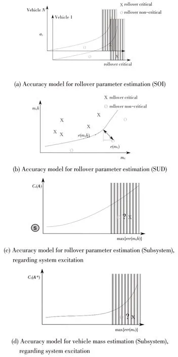
Figure 4.Accuracy models
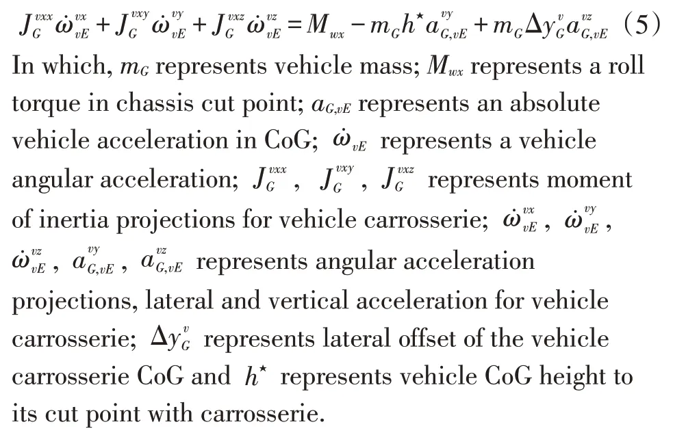
Further information for the chassis roll torque estimation could be found in[6]and[8].
Precise estimation of the critical rollover situation orSsfonly from|Δy|mGandparameters(vehicle yaw dynamic)is not possible(Shown in Figure 4b).Therefore,precise values of vehicle mass are needed.
The vehicle massmGcould be defined from longitudinal dynamic(Shown in Figure 3 SUD)as follows:

represents vehicle absolute vertical acceleration;mchassisrepresents chassis mass in its cut point to carrosserie.
Where longitudinal force is modelled asFdrv,xdriving force and driving resistance,which together with road slope angleθcause vehicle absolute longitudinal acceleration.Also vehicle vertical dynamic is used for mass estimation to exclude the deflection sensors offsets after a more prolonged standstill.
As shown also from Figure 3 and Figure 4,a SUD choice feasibility depends on the fulfilment of rollover estimation accuracy requirements.
Rollover critical manoeuvres occur by the high vehicle lateral accelerationand static stability factorSsfand marked with a red cross,shown in Figure 4.The vehicle lateral acceleration could be measured directly by the Electronic Stability Program(ESP)sensor cluster,butSsfshall be estimated for each drive asmGh⋆,,andmGvalues from the vehicle rollover Eq(5)and longitudinal Eq(6)dynamics.The accuracy requirements for rollover parameter and vehicle mass estimation in Figure 4 mean that sufficient parameter estimation accuracy(out of grey domain)could be achieved only for sufficient measurement statistic.The measurement statistic for each parameter is characterized by a conditional numbercj,shown in Figure 4 and explained below with mode details
Such accuracy requirements for rollover parameter estimation(SUD)mean sure detection of rollover critical vehicle load:

This could be achieved as defined in[6]by the following estimation accuracy for subsystems:

In which,hWPrepresents hight of the cut point between carrosserie and chassis.
The rollover accuracy requirement Eq(7)is estimated for rollover critical and non-critical loaded vehicles.The accuracy requirements for subsystems Eq(8) are obtained as a technical constraint for a particular vehicle range in several design optimization loops.The required accuracy for rollover parameter estimation(Subsystems)Eq(8)can be achieved only by sufficient measurement statistics and system excitation(conditional number for practical observabilitycj):

In which,ejis a unit vector for excitation matrixA∈R5for vehicle rollover dynamic model Eq(5):

A*∈R3for vehicle longitudinal force model Eq(6),shown in Figure 4c and Figure 4d.
The sufficient measurement statistic could not be actively initiated during the everyday drive.Therefore,it shall be evaluated as an enabler for the reliable rollover risk estimation.For the measurement statistic evaluation in[6]is used conditional number and parameter estimation accuracy models as in Figure 5.Such accuracy models are derived from the practical experiment for the representative manoeuvre catalogue.The functional algorithm design respects the available sensors,their physical model,and accuracy as technical constraints.The feasibility analysis was done due to evaluating several measurements’statistics regarding design assumptions.
The referenced manoeuvres from Figure 5 as crosses from outer surface are represent standardized slalom drives on different velocities and regular drives in street traffic.The referenced manoeuvres from Figure 5 as crosses from inner surface are represent the same manoeuvres in simulation with neglected carrosserie friction effects.

Figure 5.Estimation accuracy for the parameters mh and Jxx for unknown friction force(outer surface)and known friction force(inner surface)
4 System Design Algorithm for Research
A definition of extended stability Eq(3)is obtained from feasibility analysis and several design iterations for different assumptions for physical factors.Such manual feasibility analysis from[6]for different design assumptions could be generalized and automatized for systematic analysis of all assumptions and their combinations.
4.1 Mathematical Description of System Design
The general description of the system design approach for all mentioned in chapter 3 detail levels looks as follows:
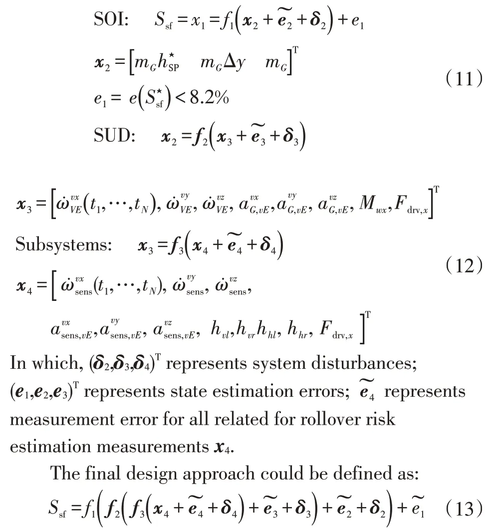
The influence of system disturbances and state estimation error could be reduced due to internal error compensation methods.
Numerical search for an optimal design approach Eq (11) or Eq (12) for all related maneuvers could take too much computation effort.Therefore,separate detail levelsf1,f2,f3are defined to reduce the complexity of each subtask.In this case,physical models (e.g.,force and torque balance) constrain design search space and ensure faster convergence to the appropriate design approach.
The following non-functional design criteria shall be respected:
a.From the economic point of view,each additional information source forx4causes expenses.
b.The highx4accuracy requirements(related to measurement’s errors)increase costs.
c.The high sensitivity to environmental disturbances means that system design has insufficient robustness.
d.The further requirements regarding modularity∕reusability could be defined for the system states.
No additional sensors are considered by the design of the rollover risk detection system but only those already planned for other driving assistance systems.
4.2 Feasibility Analysis Regarding Physical Constraints
For the rollover risk estimation,a system designf1,f2,f3is done respecting physical constraints and lows.Simultaneously,several factors could not be analytically evaluated (e.g.,rollover moments lost between chassis and carrosserie in rubber mounting points),and their impact or relevance could be estimated only in the experiment.For example,the following design factors and sensor faults could significantly affect static stability factor estimation and therefore accuracy of rollover risk estimation and prediction:
a.E.g.,sensor mounting points and mounting position faults.
b.Sensors offsets.
c.A nonlinear model for chassis rollover torqueMwx,see[6].
d.Rollover torque lost between chassis and carrosserie in rubber mounting points ΔMwx,see[8],etc.
The design complexity increases if not only singular factors but also their combination could influence design state spacex3,x4,and their impact shall be evaluated as well.
Analysis of all possible factors and their combination based on the relevant experiment set could be automated and help the researcher faster converge to the proper design approach.Therefore,the final parameter estimation accuracy shall respect the defined factors’evaluation.However,some effects could be neglectable.
4.3 Feasibility Analysis Regarding Required Accuracy
A parameter accuracy could be presented as probability-based parameter distribution,see Figure 6.

Figure 6.Probability-based parameter value distribution For the normal distribution will be assumed that

The estimation of rollover parameter accuracy also meets such kind of assumption.For some critical safety problems,for which it is essential not to underestimate the parameter,some reserve value shall be respected by the parameter estimation:

The following goals restrict the rollover parameter accuracy:
a.Ensure rollover critical vehicle load configuration.
b.Improve vehicle agility for rollover non-critical load.
Such reserve valuesres±{p}could be chosen in such a way,that parameter estimation converges will be not changed due to reserve values:

The estimation parameter accuracy depends on its turn from measurement statistics.Therefore,an accuracy model which depends on the system excitation or conditional numbercmhis provided,shown in Figure 5:

Functional goal accuracy is defined as accuracy ofSsfestimation,shown in Figure 7.
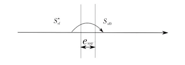
Figure 7. Ssf estimation for rollover critical vehicle load
Then rollover critical valueshall be at leasteSSFsmaller asSsf0of the empty vehicle:
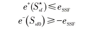
If for the uppere+(xi)and lowere-(xi)bounds of the state estimation values hold:

Then a simplified inequality for estimation errors for rollover parameters is got:

Where accuracy values for vehicle CoG shall be transformed to the parameter space of the SUD,see Eq(8)and Eq(11):

As seen from Eq(18),the maximal available estimation accuracy for vehicle rollover parameterdepends on the vehicle load.Therefore,the required parameter estimation accuracy could be found as an argumentfor the following optimization problem:

In which,αrepresents a weight coefficient matrix for the acceptable rollover parameter estimation error.
Matrixαis a free design parameter but should be chosen respecting technical constraints by estimation accuracy to ensure design feasibility.
Parametersare the closest rollover critical vehicle load for a non-critical vehicle load
The design feasibility,in this case,means that practical roll over parameter estimation erroris minor as an acceptable estimation error:

The first part of the optimization problemshall ensure that parameter estimation accuracy respects functional goal-related accuracy Eq(18).
The second part of the optimization problemshall ensure that all possible vehicle load combinations:
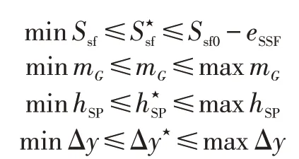
forare respected as well.
The choice of this matrixαis constrained due to practical estimation accuracy Eq(21).
Such general estimation accuracy definition is a complicated problem that depends on referenced vehicle load.Estimating required accuracy needs computation efforts depending on the vehicle model range parameters and could be done just numerically.A developer shall be supported by the numerical optimization tools and methods on this part of design requirements.As more details about model range are known,estimation accuracy could be defined.
5 Conclusion
This paper briefly describes challenges and constraints by the model-based system design method and SPES design approach.On the example of rollover risk estimation problem was shown,how such design and notation method could be applied to the research.This research design analysis could be partly automatized to increase design maturity for take over for serial production.However,further development of analysis and design derivation methods for different projects is necessary.Such design derivation shall imply feasibility analysis methods as defined in chapters 2 and 4 and respect known functional,logical,and technical constraints such as sensor accuracy,constraints regarding practical observabilities and estimation model uncertainties.An appropriate design approach shall be obtained via design optimization regarding know constraints and system accuracy budget.
