Evolution of the high-field-side radiation belts during the neon seeding plasma discharge in EAST tokamak
2022-10-26JiChanXu许吉禅LiangWang王亮GuoShengXu徐国盛YanMinDuan段艳敏LingYiMeng孟令义KeDongLi李克栋FangDing丁芳RuiRongLiang梁瑞荣JianBinLiu刘建斌andEASTTeam
Ji-Chan Xu(许吉禅) Liang Wang(王亮) Guo-Sheng Xu(徐国盛) Yan-Min Duan(段艳敏) Ling-Yi Meng(孟令义)Ke-Dong Li(李克栋) Fang Ding(丁芳) Rui-Rong Liang(梁瑞荣) Jian-Bin Liu(刘建斌) and EAST Team
1School of Mechanical Engineering,Anhui University of Science&Technology,Huainan 232001,China
2Institute of Plasma Physics,Chinese Academy of Sciences,Hefei 230031,China
Keywords: high-field-side,radiation belts,neon seeding,EAST
1. Introduction
The process of the divertor detachment is complicated.It depends on the plasma parameters, which also affect each other, such as toroidal magnetic field (Bt) direction, plasma density, heating power, and injected gas.[1]At present, there are three ways to realize the divertor detachment in experiments, i.e., increase the content of impurity in plasma by injecting impurity gas,improve ion radiation energy coefficient by using higher emissivity impurity,and increase the upstream plasma density.[2]When plasma detachment occurs, the heat and particle fluxes to the divertor targets can be effectively reduced,which is often accompanied with some local radiation phenomena in plasma boundary and core, such as the multifaceted asymmetric radiation from the edge(MARFE).[3]The location of radiation region is always affected by the plasma parameters, and meanwhile, it also easily influences on the plasma confinement.[4–6]Therefore, it is very important to control the radiation evolution for stable detachment operation of high-performance plasma.
At present, many feedback control experiments of divertor detachment have been carried out on advanced tokamaks abroad,such as ASDEX-Upgrade,[7–9]JET,[10,11]and CMOD.[12]Many signals,such as thermal current,electron temperature,ion saturation current at divertor target plates,plasma density, radiation power, and impurity line emissions, were used as reference signals to feedback control the valve actuator of pure deuterium(D2)or impurity gas seeding, for realizing the stable control of divertor detachment. In the Experimental Advanced Superconducting Tokamak (EAST), the stable plasma detachment by active feedback control has also been carried out by high density or impurity seeding,such as neon(Ne) or argon (Ar) mixed with D2.[13–16]During discharges with neon seeding in the EAST,the strong radiation belts have always been observed in the high-field-side(HFS)SOL region(named as HFS radiation belts). The formation and evolution of the radiation belts were routinely accompanied with H–L transition, the degradation of plasma performance and even disruption. This paper will focus on the behavior of the HFS radiation belts phenomenon,and Section 2 introduces the relative experimental system on EAST tokamak. The experimental results and discussion are present in Section 3. A summary is given in Section 4.
2. Experimental setup
EAST is a non-circular fully superconducting magnetic confinement facility with various auxiliary heating and current drive systems up to 30 MW, including lower hybrid current drive(LHCD),ion cyclotron resonance heating(ICRH),electron cyclotron resonance heating (ECRH) and neutral beam injection (NBI).[17]There are flexibleBtdirection and different divertor configurations (double null (DN), upper single null (USN) and lower single null (LSN)) on EAST,[18]and equipped with the upper ITER-like tungsten divertor since 2014.[19]The key diagnostic systems in the neon seeding experiments are shown in Fig.1.
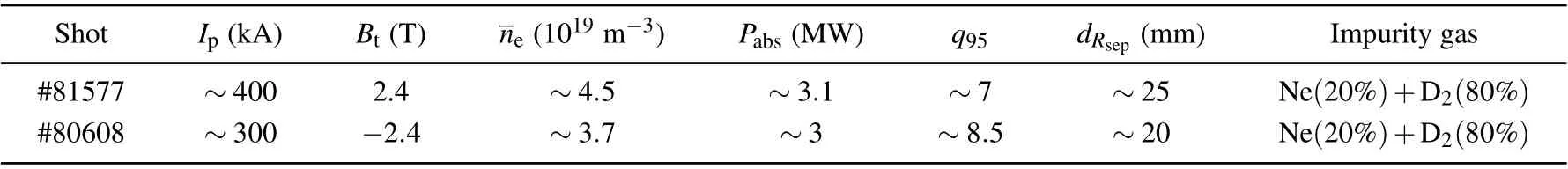
Table 1. Main plasma parameters for shots#81577 and#80608.
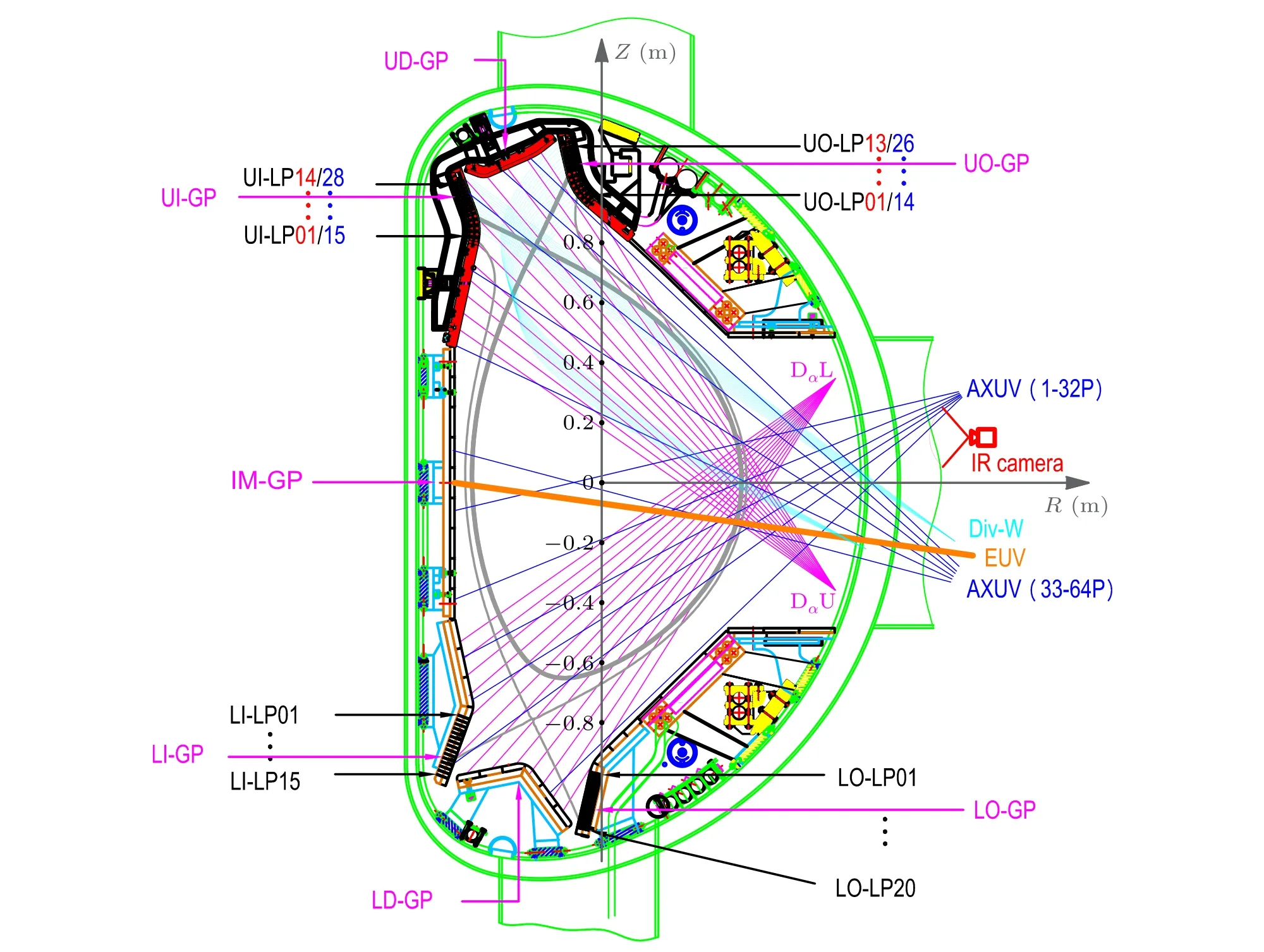
Fig. 1. Layout of the gas-puff locations (magenta) and the main diagnostics used in this study: divertor Langmuir probes (black), divertor spectroscopy(wathet blue),lines of sight of the AXUV(blue),Dα (magenta)arrays,and EUV spectroscopy(orange).
The electron temperatureTeat divertor target plates can be measured by one group of lower divertor Langmuir probe (LP) arrays located at port D, and two groups of identical upper divertor LP arrays located at ports O and D,respectively.[20,21]The radiation brightness profiles and total radiative power(Prad)can be obtained by 64-channels absolute extreme ultraviolet (AXUV) diagnostic system, which fully covers the poloidal cross-section of the plasma[22]with its vertical(Zdirection)positions marked in the black coordinate in Fig.1. The divertor Dαis measured by a filter-scope spectral diagnosis.[23]The impurity line emissions,including tungsten(W),Ne,carbon(C),and lithium(Li),in the upper divertor are measured by the multichannel visible impurity spectroscopic diagnostic.[24]The visible and infrared (IR) cameras are also equipped for recording the visible and infrared images during plasma discharges,respectively.
The neon is seeded from gas puff outlet at the upper outer divertor (UO-GP), which is located near UO-LP08. The delay time for the divertor plasma radiation response is about>200 ms depending on the impurity diffusion time, the gas pressure in the plenum and the length of tubes in divertor gas puff system.[15,25]
Shots#81577 and#80608 discussed in this paper are all operated in the USN configuration with differentBtdirections,i.e., ionB×∇Bdrift pointing upwards or downwards. As shown in Fig. 2, the last closed flux surface for the shots#81577 and #80608 att=5 s are given, and both the outer strike point locates at near UO-LP10. With this magnetic configuration, the injection impurity gas can directly affect the divertor plasma in the range of~3 cm near the strike point of the UO divertor target plate.[14–16,26,27]Actually, the magnetic configuration in EAST tokamak is a near DN configuration,and thus,there is a primary X-point in the upper divertor region and a secondary X-point in the lower divertor regions during the USN discharges,as shown in Fig.2.

Fig.2. The last closed flux surface of shots#80608(light green)and#81577(light blue) calculated by the magnetic equilibrium. Impurity seeding location(brown)and divertor Langmuir probe locations(circles along the target plate) with No. 5 and No. 10 probes (No. 15 for lower outer (LO) divertor probes)in red circles. Lines of sight of the AXUV arrays(deep yellow)from channel 52 (ch52) to channel 63 (ch63) near the primary X-point (upper),and from channel 2 (ch2) to channel 13 (ch13) near the secondary X-point(lower).
3. Experimental results and discussion
During 2019 EAST campaign,a series of detachment experiments were carried out by Ne or Ar mixed with D2seeding from the UO-GP.[28]The effect of different magnetic configurations on plasma detachment with impurity seeding is studied by changing theBtdirection. In this paper,two representative shots with different magnetic configurations are presented to show the characteristics of radiation belts during neon seeding.The main plasma parameters of shots#81577 and#80608 with differentBtdirection are listed in Table 1, including plasma current (Ip),Bt, line-average plasma density (ne), absorbed heating power (Pabs), edge safety factor (q95), anddRsepand impurity gas. The two shots are mainly used to study the feedback control method of radiation divertor by Ne+D2mixed gas seeding from the UO-GP.Shot#81577 is operated to feedback control the total radiated power by injecting pulsed impurity gas,while shot#80608 is operated to feedback control the peak ion saturation current near strike point by injecting continuous impurity gas.[14,16,29]In the following, the characteristics of HFS radiation belts in the two discharges with different magnetic fields will be investigated.
3.1. Behavior of radiation belts in USN with B×∇B ↑
As shown in Fig. 3, in shot #81577, the neon line emissions summation(NeII421.97nm)in the upper divertor and the total radiation power (Prad) in the core keep increasing, indicating that the neon is continuously injected into the plasma.Meanwhile, the peak temperature (TIRpeak) of the UO divertor target plate decreases continuously, indicating that neon impurity seeding has a good protective effect on the divertor.The averaged electron temperature near the UO strike point(Tet,avg@OSP,which is the average value of the electron temperatures measured by three divertor Langmuir probes near the UO strike point)also continuously decreases and finally falls below 10 eV,indicating that the plasma in the area of the UO divertor has entered the detachment state. While the averaged electron temperature near the strike point at upper inner (UI)divertor (Tet,avg@ISP, which is the average value of the electron temperatures measured by three divertor Langmuir probes near the UI strike point)always remains below 10 eV,indicating that the plasma in the UI divertor has been in the detachment state before the impurity seeding.[30]

Fig.3.Divertor impurity seeding with 20%Ne+80%D2 mixed gas from UOGP in EAST shot#81577. Time traces of(a)neon line emissions summation in divertor and valve voltage of the impurity gas puff,(b)plasma density and plasma stored energy, (c) total heating power (Ptotal black), radiation power in the core(Prad red)measured by AXUV arrays,power across the separatrix(Psep green) and the L–H transition threshold power (PL–H magenta dotted line), (d) Tet,avg@OSP, Tet,avg@ISP, and TIRpeak on the upper divertor target plate, (e) AXUV diode signal of channel 58 (AXUV58) near the primary X-point and(f)its power spectrogram.
As shown in Fig. 3(c), the power across the separatrixPsep=Ptotal-Prad- dWMHD/dtdecreases during the neon seeding. The L–H transition threshold powerPL–H~1.74 MW calculated by the L–H conversion power threshold calibration formula for International Tokamaks,[31]
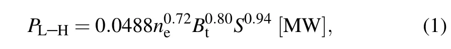
whereneis the linear average density [1020m-3],Btis the toroidal field intensity [T] andSis the plasma surface area[m2]. When thePsepdecreases to thePL–H at~4.86 s, the stored energyWMHDreduced by about 50 kJ.Meanwhile,the plasma densityneis also disturbed and gradually reduced to 4×10¹⁹m-3(Fig.3(b)),and the small grassy ELMs immediately disappear shown in the AXUV58 signal passed near Xpoint(Fig.3(d)),all indicating that the H–L transition occurs in plasma discharge.As shown in Fig.3(e),with the beginning of neon seeding at 3.5 s,the UO divertor target changes from attachment to partially detachment. The radiative fluctuation with a frequency of 5 kHz–6 kHz at the X-point gradually decreases and transforms into a wide band around 3 kHz. However, when H–L transition occurs at~4.86 s, this wide band disappears immediately.[32,33]
As shown in Fig. 4, shot #81577 is divided into three phases, i.e., Phase I: H-mode plasma with pulsed neon seeding,Phase II:L-mode plasma before the movement of the radiation belts, and Phase III: movement of radiation belts before disruption. During Phase I, the intensities of Dα, impurities (W, C, Li) line emissions in upper divertor andZeffare basically unchanged, and a strong radiation near X-point is measured by AXUV arrays,see Fig.4(d). When transiting to Phase II, an obvious increase of Dαin upper divertor and Li line emission are observed. The Dαin lower divertor just increase slightly.The W line emission remains at a low intensity value. The C line emission andZeffdecrease. In addition, as shown in Fig.4(d), after a pulse of neon seeding at 4.8 s, the radiation signal is significantly enhanced. Then H–L transition happens, and then main radiation region begins to move downward. Finally, stably located at HFS SOL with a certain distance from X-point,where the channel 54 AXUV line is located. It is also clearly observed in the CCD camera, as shown in Figs.5(b)–5(f),a stable and bright belt appears in the toroidal direction. As the pulsed neon seeding after 5.4 s,the main radiation region moves further downward along the HFS SOL, see Phase III in Fig. 4(d), and the position of the peak radiation signal measured by AXUV arrays goes down to the lower divertor region. It is also obviously observed from the CCD images in Fig. 6, the position of radiation belts moves from upper divertor to lower divertor. During Phase III, the intensities of Dα, W and Li lines in upper divertor decrease,and there is a spike inZeffat~5.46 s,then it drops fast. After Phase III,when the radiation belts locate at HFS SOL near the secondary X-point in the lower divertor region,the plasma disruption occurs very quickly.

Fig.4. Time traces of(a)Dα line emissions in the upper divertor and lower divertor region,(b)W and C line emissions summation measured by divertor spectroscopy, (c) Li line emission summation in the upper divertor and effective ion charge Zeff in the core,(d)radiation brightness profiles measured by two AXUV arrays with the value voltage of the impurity gas puff(black solid line)and location of X-point(black dotted line,Z=~0.6 m)in the shot#81577.
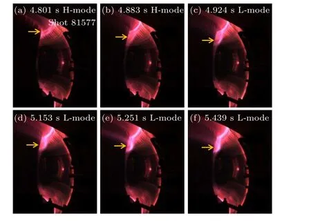
Fig.5. Images measured by a wide-angle CCD camera in shot#81577 with impurity seeding. (a)to(f)show the formation and maintenance of a radiation belt on the HFS SOL in the upper divertor near X-point during the H–L transition phase,the orange arrows point to the position of radiation belts.
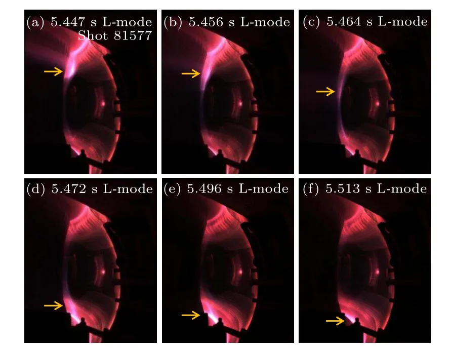
Fig.6. Images measured by a wide-angle CCD camera in shot#81577 with impurity seeding. (a)to(f)show the downward movement of a radiation belt on the HFS SOL from the upper divertor to the lower divertor in the L-mode phase before plasma disruption, the orange arrows point to the position of radiation belts.
3.2. Behavior of radiation belts in USN with B×∇B ↓
As shown in Fig. 7, the neon line emissions summation in the upper divertor andPradincrease when the valve is opened (Vvalve>2.5 V) in the shot #80608. Meanwhile,TIRpeak,Tet,avg@OSP andTet,avg@ISP continuously decrease and finally the electron temperature falls below 10 eV,indicating that the onset of detachment at UO and UI divertor regions.As shown in Fig. 7(c),Psepapproaches toPL–H at~4.69 s.At this time,WMHDstarts to be reduced by about 25 kJ, andneis also disturbed and gradually reduced to 3.5×10¹⁹m-3(Fig. 7(b)). Besides, as shown in Figs. 7(d) and 7(f), the radiative fluctuations with a low frequency of~0.1 kHz near the primary X-point form before seeding. With the increase of neon seeding,it transforms into a wide band around 3 kHz.However, the wide band radiative fluctuations disappear immediately at~4.69 s,then the H–L transition occurs.[14,32]

Fig.7.Divertor impurity seeding with 20%Ne+80%D2 mixed gas from UOGP in EAST shot#80608. Time traces of(a)neon line emissions summation in the upper divertor and valve voltage of the impurity gas puff, (b) plasma density and plasma stored energy, (c) Ptotal (black), Prad (red), Psep (green)and PL–H (magenta dotted line),(d)Tet,avg@OSP,Tet,avg@ISP and TIRpeak on the upper divertor target plate,(e)AXUV58 and(f)its power spectrum.
As shown in Fig. 8, we also divide the shot #80608 into three phases,i.e.,Phase I:H-mode plasma with a pulse of neon seeding,Phase II:L-mode plasma before the movement of the radiation belts,and Phase III:movement of radiation belts before disruption. During Phase I, the intensities of Dα, impurities (W, C) line emissions summation in upper divertor decrease after neon seeding,while the intensities of Dαin lower divertor and Li line emissions summation increase slightly. As shown in Fig.8(d),we found that the primary radiation region locates near the primary X-point at first.However,after injecting neon gas for about 200 ms,a strong radiation region forms near the secondary X-point measured by AXUV arrays, and becomes a peak. In Phase II,theDαin the upper and lower divertor basically remain unchanged after a pulse of disturbance,and the Li line emission also remains unchanged,while the W and C line emissions decrease yet. As shown in Fig.8(d),the radiation region near the secondary X-point jumps to the upper divertor area almost immediately, then quickly moves downward during the pulse disturbance. Finally, stably located at HFS SOL with a certain distance from the secondary X-point,where the channel 12 AXUV line is located.It is also observed by the CCD camera,as shown in Figs.9(c)–9(f),a stable and bright belt appears in the toroidal direction, and the radiation intensity enhances slightly. After~5.16 s, the main radiation region moves further upward along the HFS SOL,see the CCD images from Figs.10(a)–10(f). When entering Phase III in Fig.8(d),the position of the peak radiation signal measured by AXUV arrays goes up to upper divertor region. In Phase III,the intensities of Dα,W and Li lines in the upper divertor increase,while the Dαin the lower divertor and C line in the upper divertor appear to downtrend.Finally,the radiation belts stay at HFS SOL near the primary X-point in upper divertor region. However, after a sudden increase in the radiation intensity,the radiation area expands to core plasma,then leading to plasma disruption.
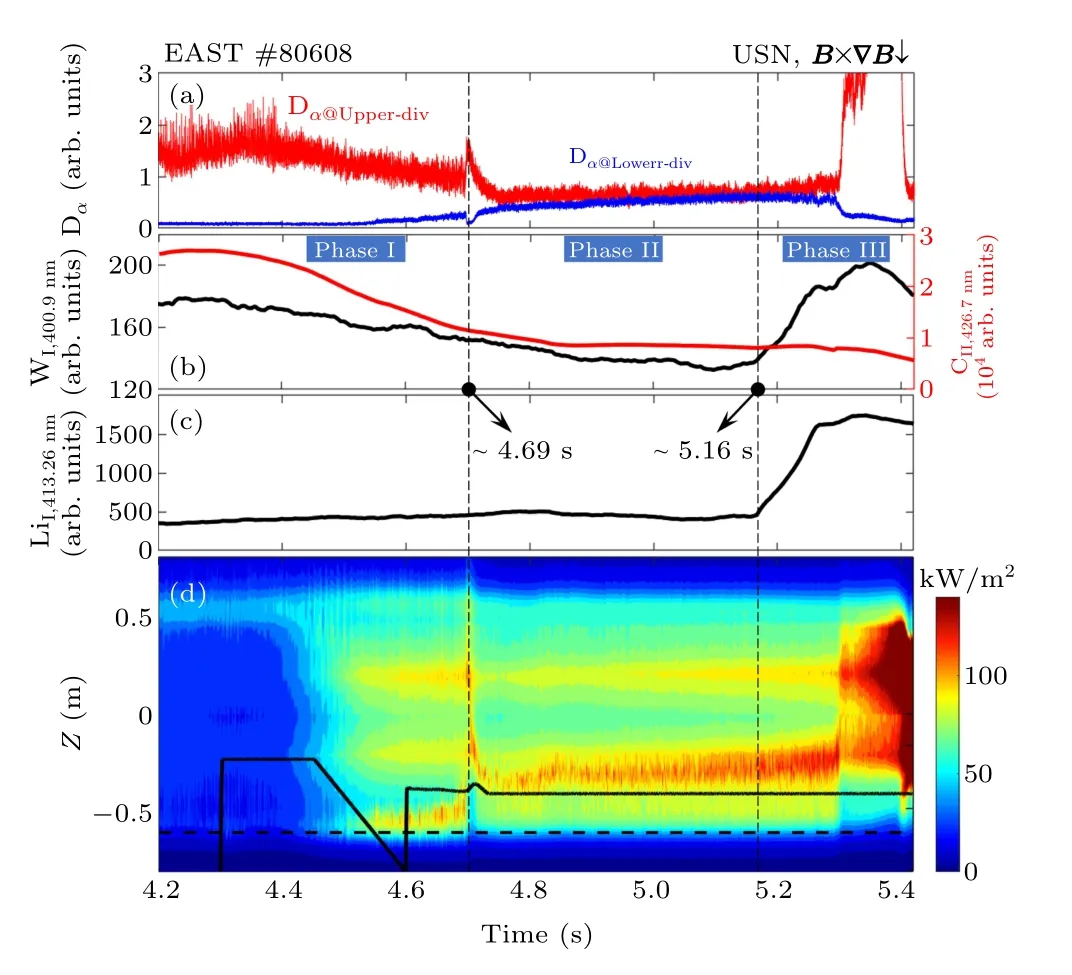
Fig.8. Time traces of(a)Dα line emissions in the upper divertor and lower divertor region, (b) W and C line emissions measured by divertor spectroscopy, (c)Li line emission, (d)radiation brightness profiles measured by two AXUV arrays with the valve voltage of the impurity gas puff(black solid line) and location of secondary X-point (black dotted line, Z ~-0.6 m) in lower divertor in EAST shot#80608.

Fig. 9. Images measured by a wide-angle CCD camera in shot 80608 with impurity seeding. (a) to (f) show the formation and maintenance of a radiation belt on the HFS in the lower divertor near X-point during the H–L transition phase,the orange arrows point to the position of radiation belts.

Fig.10. Images measured by a wide-angle CCD camera in shot 80608 with impurity seeding. (a)to(f)show the upward movement of a radiation belt on the HFS from the lower divertor to the upper divertor in the L-mode phase before plasma disruption,the orange arrows point to the position of radiation belts.
3.3. Discussion
As mentioned above, during divertor detachment by the neon seeding,a strong HFS radiation belt evolution can be observed in two magnetic configurations in EAST tokamak,that is, in the USN configuration withB×∇B ↑(toroidal magnetic fieldBis in the co-Ip direction)andB×∇B ↓(Bis in the ctr-Ip direction), as clearly shown in Fig.11. In the USN shot#81577 withB×∇B ↑,see Fig.11(a),the radiation belt appears near the primary X-point in the upper divertor(Loc.1).With the increase of the radiation power, the H–L transition can be triggered. Then the radiation belt starts to move downward and finally stabilizes at Loc.2. As the neon seeding continues to increase,it will move downward along the HFS SOL from Loc.2 to Loc.5.The radiation belt may expand to the core plasma at Loc.5 and induces disruption. However,as shown in Fig. 11(b), in the USN shot #80608 withB×∇B ↓, the radiation belt appears near the secondary X-point in the lower divertor region (Loc.1) after neon seeding. When entrancing L-mode discharge,it will move to Loc.2 and stay there. With the increase of radiation power,the main radiation belt quickly moves upward along the HFS SOL from Loc.2 to Loc.5 in~180 ms. The radiation belt also may expand to the core plasma at Loc.5,and induces plasma disruption.
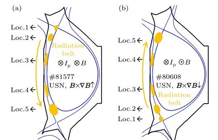
Fig.11. Schematic poloidal view of formation and evolution of HFS radiation belts with(a)B×∇B ↑(b)B×∇B ↓in the USN magnetic configurations. The yellow single-ellipse and yellow arrows indicate the poloidal location and evolutionary trend of the HFS radiation belts during the neon seeding plasma discharges. Loc.1 to Loc.5 mark the location of radiation belts.
Actually,this phenomenon is often observed during neon seeding plasma discharges in EAST,especially in the disruption discharges caused by injecting excessive neon. Figure 12 shows the evolution of HFS radiation belts in the USN discharge(shot#80442)withB×∇B ↑,Ip=400 kA,and feedback control ofjsatby injecting 5%Ne and 95%D2mixed gas from the UO-GP.Before~2.5 s with L-mode plasma,the radiation belts stay at the Loc.2(as shown in Fig.11(a)). As the heating power increases, the plasma transits to the H-mode,and the radiation belts gradually move towards the Loc.1,coexisting with the H-mode discharge. After neon seeding at 4 s,theTe,avg@OSP drops and the radiation belts begin to expand,then the H–L transition occurs instantaneously at~4.36 s. At the same time, the radiation belts move from Loc.1 to Loc.2.When the injected impurity gas decreases,the discharge backs to H-mode at~4.5 s, the radiation belts also back to Loc.1.With the increase of neon seeding, the plasma transits to Lmode at~4.86 s again, and the radiation belts continue to move downward until the discharge disruptions. The results indicate that the location of the radiation belts is closely related to the radiation power and plasma confinement performance in the USN discharges withB×∇B ↑,i.e.,when the radiation power is high enough, the H–L transition may occur, the radiation belts will move from Loc.1 to Loc.2 at this time, and even continue to move downward until disruption happens.
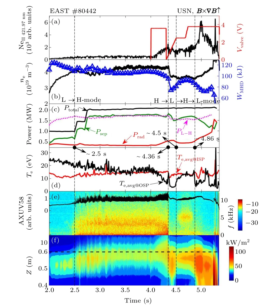
Fig. 12. Divertor impurity seeding with 5%Ne+95%D2 mixed gas from the UO-GP in EAST shot #80442. Time traces of (a) neon line emissions summation in divertor and valve voltage of the impurity gas puff,(b)ne and WMHD,(c)Ptotal (black),Prad (red),Psep,and PL–H (magenta dotted line),(d)Te,avg@OSP and Te,avg@ISP near the strike point on UO and UI divertor target plates,(e)AXUV58 chords and its power spectrogram,and(f)radiation brightness profiles measured by two AXUV arrays and location of primary X-point(black dotted line,Z=~0.6 m)in the upper divertor.
Figure 13 shows the evolution of HFS radiation belts in the USN discharge (shot #80607) withB×∇B ↓,Ip=300 kA, by injecting 20%Ne+80%D2mixed gas from the UO-GP.As the injection of impurity gas,the plasma discharge maintains H-mode,while the radiation belt shifts to the Loc.1(as shown in Fig. 11(b)). When the neon line emission suddenly increases,the plasma transits to the L-mode at~6.25 s,and the radiation belts jump to the upper divertor area. Then it quickly moves downward and finally stably located at Loc.2,as observed in shot #80608. After~6.38 s, the neon line emission increases greatly, and the radiation belts cross the middle plane and gather at HFS SOL near the upper divertor region (Loc.4). During this period, both theTe,avg@ISP andWMHDdrop to their extremum value, then begin to increase, and when the neon line emission drops at~6.81 s,the HFS radiation belts back to Loc.2 and stay there until they disappear at~7.34 s. Meanwhile, the peak radiation region returns to primary X-point in the upper divertor region, then L–H transition happens at~7.54 s. The results indicate that the formation and evolution of the HFS radiation belts are not only related to the radiation power and plasma confinement performance,but also may be affected by the electron temperatures at divertor target plates. That is, the state of divertor detachment also affects the HFS radiation belts, which tends to move upward when the electron temperature at UI divertor target plate is low.
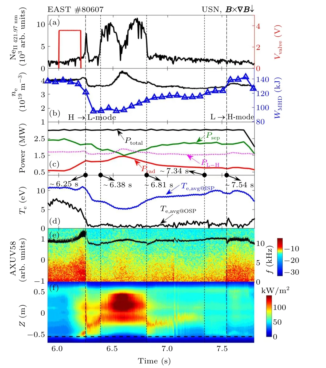
Fig. 13. Divertor impurity seeding with 20%Ne+80%D2 mixed gas from the UO-GP in EAST shot #80607. Time traces of (a) neon line emission and valve voltage of the impurity gas puffing, (b) ne and WMHD, (c) Ptotal(black),Prad (red),Psep and PL–H (magenta dotted line),(d)Te,avg@OSP and Te,avg@ISP near the strike point on UO and UI divertor target plates, (e)AXUV58 chords and its power spectrum, and (f) radiation brightness profiles measured by two AXUV arrays and location of secondary X-point(black dotted line,Z=~-0.6 m)in the lower divertor.
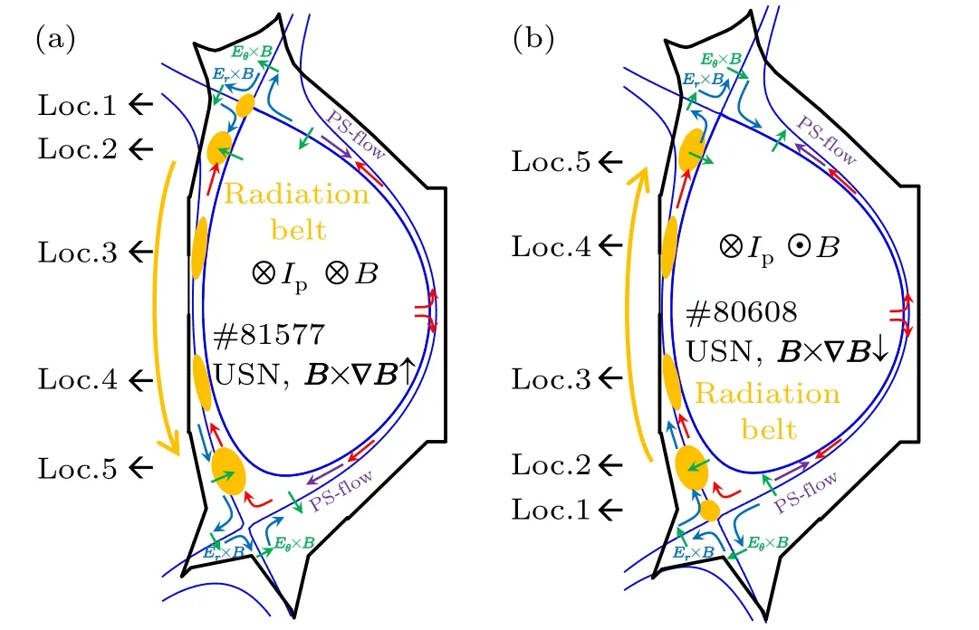
Fig. 14. Schematic poloidal view of the drifts, parallel flows with (a)B×∇B ↑(b)B×∇B ↓in the USN magnetic configurations with Er×B drift (blue arrows), Eθ ×B drift (green arrows), ion Pfirsch–Schl¨uter (PS)flow (purple arrows) and SOL flow (red arrows). The yellow single-ellipse and yellow arrows indicate the poloidal location evolution of radiation belts in the high-field side SOL during the plasma discharges.Loc.1 to Loc.5 mark the location of radiation belts.
The HFS radiation belts are widely found in the discharges with high-density or impurity injection on many tokamaks. Generally,drifts and parallel flows are considered play important roles on its formation and evolution,[5,6,34–36]such as radial electric field drift (Er×B), poloidal electric field drift(Eθ×B),ion Pfirsch–Schl¨uter(PS)flow and SOL flow,as shown in Fig.14. In EAST tokamak,the drifts and parallel flows may also be a possible explanation for the HFS radiation belt phenomenon under different magnetic field configurations. During the H-mode neon seeding plasma discharge,the HFS radiation belts at Loc.1 form after neon seeding,and the plasma confinement performance is basically unaffected.Both onset of detachment at outer and inner divertors, it is a good regime to achieve steady-state H-mode operation with the radiative divertor,which has been verified in the EAST radiation feedback control experiments.[15,29]The radiation belts at Loc.1 are similar to the observation of the ‘MARFE-like X-point radiation’ at AUG[33]and JET.[37]But the 2-D distribution of radiation area cannot be given on EAST, thus,we are not completely sure yet if it is the same as ‘MARFElike X-point radiation’phenomenon. As the increase of neon seeding,Psepwill decrease, and easily trigger H–L transition.When shifting to L-mode, the SOL flow becomes weak andEθ×Bis enhanced, and as shown in Fig. 14, a high-fieldside–high-density (HFSHD) region will be formed at Loc.2,where easily generate plasma radiation and form a strong radiation region.[35]As the radiation power continues to increase, the plasma confinement performance further declines andEr×Bstrengthens, thus pushing the HFSHD to move and cross the mid-plane. Once the radiation belts reach Loc.5,due to theEθ×Bpoints to core plasma, it will extend the radiation region to the core plasma, which is easy to cause the plasma confinement performance degradation significantly and even induce plasma disruption.
4. Summary
This paper focuses on the formation and evolution of the HFS radiative belts during neon seeding plasma discharge in EAST tokamak.We found that the neon seeding from the UOGP can achieve the divertor detachment,and usually is accompanied by strong radiation belts in the HFS SOL region. In USN divertor configuration withB×∇B ↑,the strong radiation belts form and stay at near primary X-point after neon seeding. With the seeding of the Ne+D2mixed gas, the radiation power increases,and the plasma discharge will transit from H-mode to L-mode. Meanwhile,the radiation belts start to move from the near primary X-point to a certain distance away primary X-point in the HFS SOL region. When the radiation power continues to increase to higher level,the radiation belts will move further to the secondary X-point along the HFS SOL.It can even expand to the core plasma,and induce plasma disruption. However, in the USN divertor configuration withB×∇B ↓,when the Ne+D2mixed gas is continuously fed back to seed,the characteristics of the radiation belts show the opposite trend. Firstly, the radiation belts form near the secondary X-point during H-mode discharge. Then shifting to a stable position at a certain distance away secondary X-point in the HFS SOL region after transit to L-mode. Finally, it even moves to the primary X-point,and induces disruption.
The experimental results show that the formation and evolution of HFS radiation belts are closely related to the amount of injected neon gas. An appropriate amount of neon gas can form a radiation belt near X-point,which is conducive to maintaining the plasma confinement performance and achieving the divertor detachment. However,when seeding excess neon gas with a high radiation power,H–L transition will be easily triggered and resulting in the movement of radiation belts, even moving towards another X-point until disruption. Thus, the radiation power is an important controlled quantity, and the location of radiation belts can also be considered as a control parameter in the neon seeding feedback control experiments.
In addition, a possible physical mechanism is discussed and argued that the behavior of the radiation belts strongly depends on the drifts and parallel flows. However, due to the limitation of existing EAST diagnostic system, the detail radiation sources and accurate 2-D distribution of the radiation belts cannot be obtained. Thus,the precise formation and evolution of the radiation belts need to be further studied in the following EAST experiments, especially the quantitative relationship between the radiation belts and the operation parameters of divertor detachment, such as the radiation power,plasma confinement performance,and state of divertor detachment,which can contribute to developing more accurate feedback control algorithm for high-performance radiation divertor operation modes.
Acknowledgments
The authors would like to acknowledge the support and contributions from the rest of the EAST team. Project supported by the National Magnetic Confinement Fusion Energy Research and Development Program of China(Grant Nos. 2017YFE0301300 and 2019YFE03030000),the National Natural Science Foundation of China(Grant Nos. 12005004, 11922513, and U19A20113),and Anhui Provincial Natural Science Foundation (Grant No.2008085QA38).
猜你喜欢
杂志排行

Chinese Physics B的其它文章
- Design of vertical diamond Schottky barrier diode with junction terminal extension structure by using the n-Ga2O3/p-diamond heterojunction
- Multiple modes of perpendicular magnetization switching scheme in single spin–orbit torque device
- Phase-matched second-harmonic generation in hybrid polymer-LN waveguides
- Circular dichroism spectra of α-lactose molecular measured by terahertz time-domain spectroscopy
- Recombination-induced voltage-dependent photocurrent collection loss in CdTe thin film solar cell
- Development of ZnTe film with high copper doping efficiency for solar cells