Accelerator System of Wuhan Light Source PhaseⅠProject
2022-10-10LIHaohuNIEYuancunWANGJikeZHANGJingminHAOXueruiXIANGPaiWEIGengLIJianWANGYongHEJianhua
LI Haohu, NIE Yuancun, WANG Jike, ZHANG Jingmin, HAO Xuerui, XIANG Pai, WEI Geng, LI Jian, WANG Yong, HE Jianhua
(The institute of Advanced Studies, Wuhan University, Wuhan 430072, China)
Abstract: The accelerator system of Wuhan Light Source (WHLS), a fourth-generation synchrotron radiation facility, its phase Ⅰ project consists of a low energy storage ring (1.5 GeV) and a full energy linac injector. Based on hybrid-7BA lattice structure, the storage ring was designed as an 8-cell, 500 mA and 1.5 GeV electron synchrotron, with circumference 180 m and nature emittance 222.8 pm·rad, which reaches soft X-ray diffraction limit. At the middle of each standard cell, a 3.5 T super bend magnet was used to extend the photon energy to hard X-ray region. A 3rd harmonic cavity was designed for bunch lengthening to keep sufficient lifetime and swap-out injection scheme was chosen due to the small dynamic aperture. A full energy S-band LINAC, which is 6 meters lower than the storage ring, will be used as its injector. More details of WHLS phase Ⅰ project will be described in this paper.
Key words:light source; diffraction limit storage ring; lattice design; LINAC
CLCnumber: TL54Documentcode: AArticle IC:1000-6931(2022)09-1860-09
doi: 10.7538/yzk.2022.youxian.0360
Received Date:13 May 2022;Revised Date:23 June 2022
Funding:Supported by Science and Technology Major Project of Hubei Province (2021AFB001)
武汉光源一期工程加速器系统
李浩虎,聂元存,王纪科,张静敏,郝雪瑞,向 Π, 魏 耕,李 健,王 勇,何建华
(武汉大学 高等研究院,湖北 武汉 430072)
摘要:武汉光源一期工程计划建造一台第4代同步辐射装置,由1台1.5 GeV的低能量储存环和1台全能量直线注入器组成。储存环设计周长180 m,由8个标准混合型的7BA磁聚焦结构单元周期组成,能够储存500 mA的1.5 GeV电子。储存环自然发射度优化至222.8 pm·rad,可达到软X射线的衍射极限。为了满足用户对硬X射线的需求,每个标准单元的中心处安装了1台3.5 T的超强二极铁。同时为了提高因发射度减小造成的低寿命和动力学孔径过小造成的注入困难等问题,储存环的设计中还使用了三次谐波腔用于束团拉伸以及替换式注入系统等措施。全能量直线加速器位于储存环地下6 m处,采用S波段加速结构。本文将对武汉光源一期工程加速器系统进行更加详细的介绍。
关键词:光源;衍射极限储存环;磁聚焦结构设计;直线加速器
1 Introduction
Synchrotron radiation facility is one of the most powerful tools in science and technology research. After over a half century’s development, the diffraction limit storage ring becomes the most dominant trends, i.e., the fourth-generation light source. MAX-Ⅳ[1]in Sweden, ESRF-EBS[2]in France and Sirius[3]in Brazil are the first three constructed fourth-generation light sources in the world, and there are more than ten labs which plan to build a new machine or upgrade their recent third-generation facilities, such as DIAMOND Ⅱ[4]in England, APS-U[5]and ALS-U[6]in America, SLS Ⅱ[7]in Swiss, Spring-8 Ⅱ[8]in Japan, etc. In China mainland, HEPS[9]is now under-construction in Beijing and HALS[10]will start construction this year in Hefei. As the economic, cultural, science and technology center of central China, Wuhan is also planning to build an advanced synchrotron radiation facility in the near future.
2 Wuhan Light Source (WHLS) overview
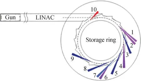
WHLS phase Ⅰ project is designed as a fourth-generation light source, which consists of a low energy storage ring (1.5 GeV), a linac working as a full energy injector and ten beamlines, as shown in Fig.1. Table 1 shows the parameters comparison between the light source with the similar electron energy in the world. The main design goals of the phase Ⅰ accelerator system are: circumference: <200 m; energy: 1.5 GeV; natural Emittance: <250 pm·rad; beam current: 500 mA; beam lifetime: >5 hours.
1—Multifunction extreme ultraviolet lithography technology; 2—Extreme ultraviolet lithography applications; 3—In-situ X-ray absorption spectroscopy; 4—Nano-focused multi-dimensional electronic structure; 5—In-situ X-ray diffraction and SAXS; 6—VUV photoelectron spectroscopy and fluorescence spectroscopy; 7—Soft X-ray absorption and emission spectroscopy; 8—In-situ surface diffraction; 9—Protein crystallography and biomedical application; 10—Infrared spectroscopy and imaging Fig.1 Layout of WHLS phase Ⅰ project
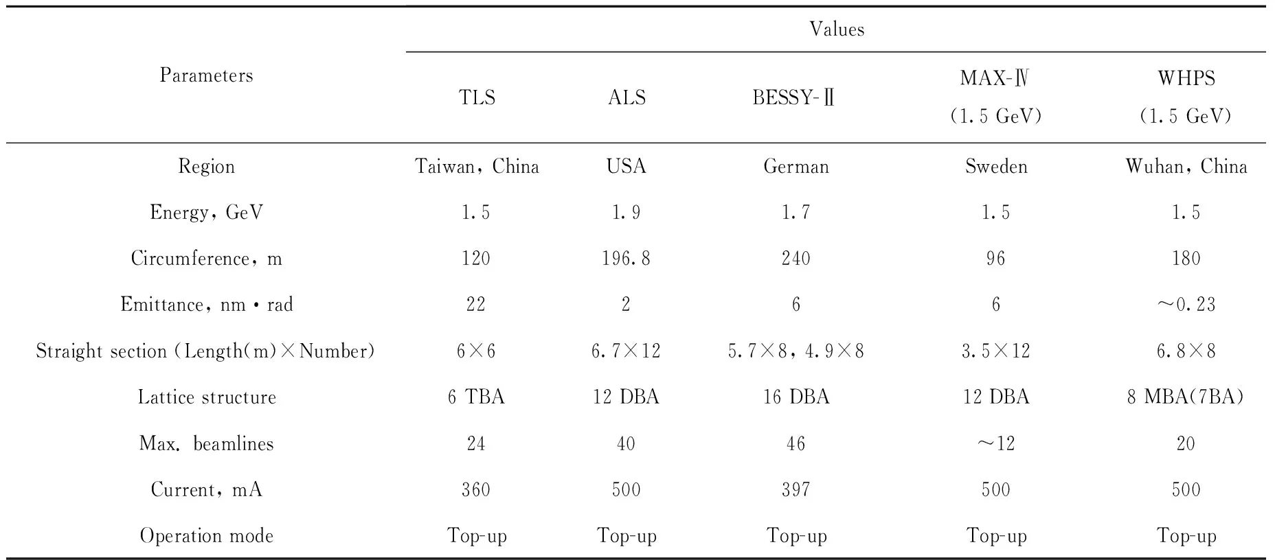
Table 1 Parameter comparison between light sources with similar energy
By using 3.5 T super bending magnet, the photon energy of the low energy ring is extended to hard X-ray region. In the phase Ⅰ project, ten beamlines are planned to build, as shown in Fig.1.
In the following sections, the design of the WHLS phase Ⅰ accelerator system will be described briefly.
3 1.5 GeV Stoarge ring LATTICE
WHLS 1.5 GeV storage ring, with 180 m circumference, is designed to use a MBA lattice structure with eight standard cells and eight 6.8 m straight sections. One straight section will be used for the injection and extraction system, one for the RF system and the bunch stretching system, and the remaining six sections for the insertion devices.
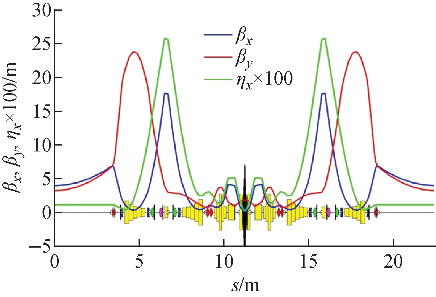
Fig.2 Optical function and magnet layout of one cell of storage ring
Like ESRF-EBS scheme[11], the lattice is using 7BA structure. Each standard cells includes seven transversal and longitudinal gradient combined dipoles. To minimize the beam emittance as much as possible, four reversed bending magnets, which combined with quadrupoles, are also used in the lattice. Another ten quadrupoles are used for optic matching and six sextuples, combined with skew quadrupole coil and H/V corrector are used for the non-linear optimization, as shown in Fig.2. The nature emittance of the low energy storage ring is 222.8 pm·rad and the beta function at the middle of the straight section are 4.0 m and 3.2 m in horizontal and vertical, respectively. Table 2 shows the main parameters of the 1.5 GeV storage ring.
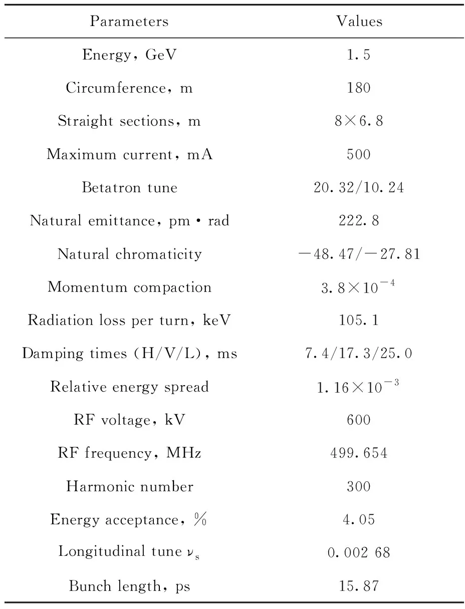
Table 2 WHLS 1.5 GeV storage ring main parameter
Fig.3 shows the dynamic aperture at the center of the straight section. With 10 mm and 4 mm for on- and off-momentum particles, respectively, it is big enough for swap-out injection requirement.Fig.4 shows the energy acceptance along the ring. The minimum value of energy acceptance along the ring exceeds 3%, and the average value is -4.2% to 3.5%, combined with 20% coupling and a 3rd harmonic cavity for bunch lengthening, the Touschek lifetime at 500 mA will be about 5 hours, which will satisfy the need of the top-up operation.Fig.5 shows the frequency map analyzing result for on-momentum particles, which is tracked 2 048 turns with radiation and RF off. There are two strong resonance lines which may cause the beam instability, 3vx=61 and 4vx+vy=64.
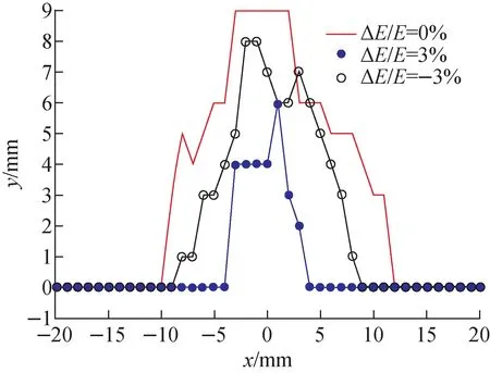
Fig.3 Dynamic aperture at the center of 1.5 GeV storage ring straight section
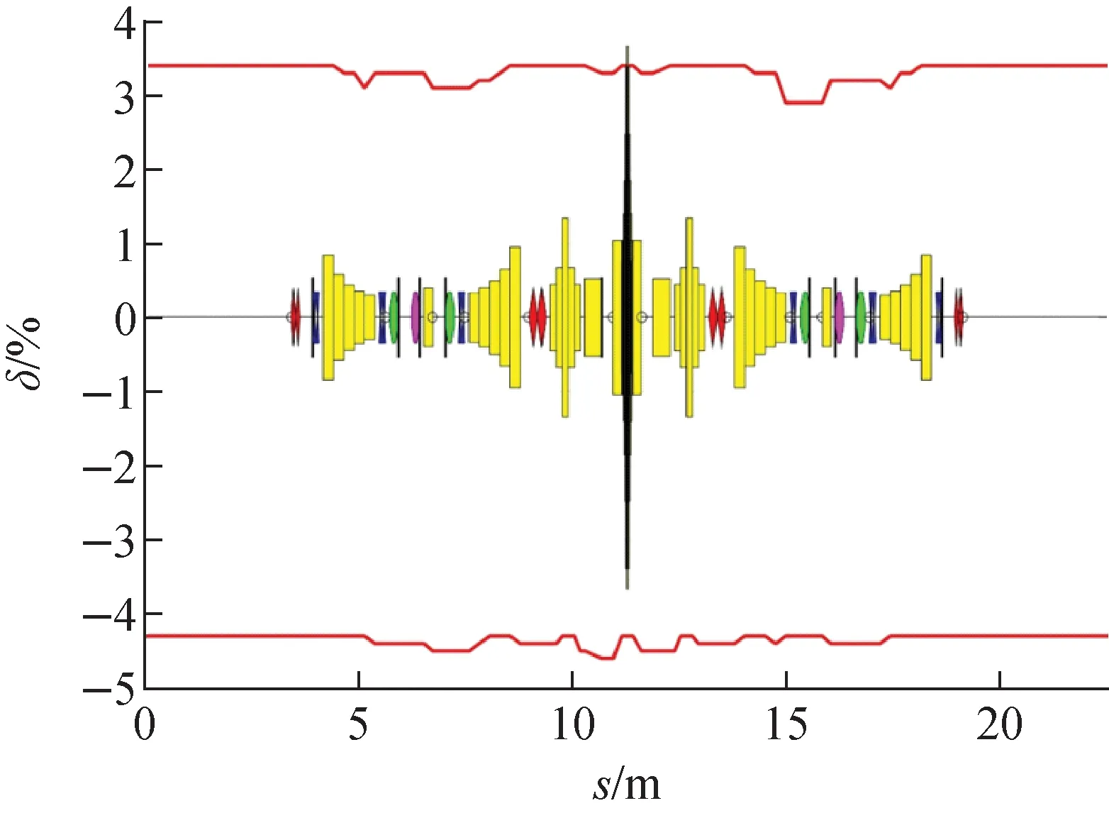
Fig.4 Energy acceptance along storage ring (one standard cell)
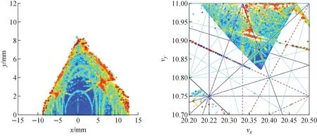
Fig.5 On-momentum FMA at injection point
4 Error and correction
Detailed error analysis and its requirements are one of the most important contents in the storage ring design. According to the particle tracking analyzing results, the 1.5 GeV storage ring alignment error rms values are set to 80 μm and 80 μrad, and the magnetic field error RMS value is 5×10⁻⁴, respectively.Fig.6 shows the dynamic aperture of the on-momentum particles at the injection point with 100 random multipole error settings.
The storage ring orbit correction system includes BPMs and correctors, and all of them are horizontal and vertical combined. Each 7BA cell includes twelve BPMs and nine correctors. Six of the correctors are combined in the sextuples and other three are independent. The final corrected COD RMS value is about 50 μm in horizontal and 40 μm in vertical, respectively. The orbit correction simulation assumes a corrector error of 0.5% and a BPM reading error of 0.2 μm. The strongest corrector strength does not exceed 2 mrad.
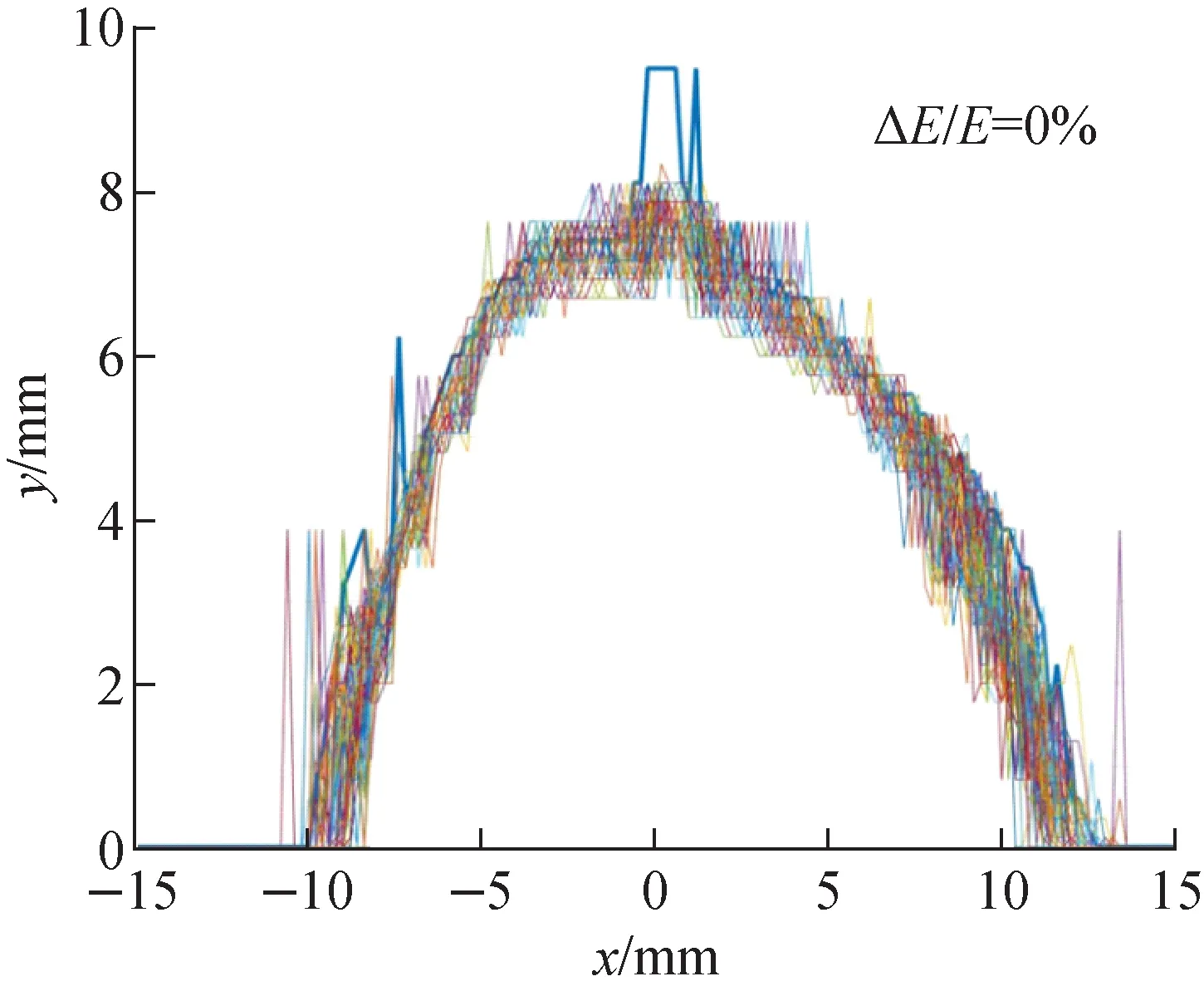
Fig.6 Dynamic aperture at injection point (100 seeds)
5 Magnet system
Four different types of dipoles are used in the ring and their field distribution is shown in Fig.7. The dipole strength order for Bend1 and Bend7 is reversed, and so do Bend2/Bend6 and Bend3/Bend5. All dipoles are designed with combined transversal and longitudinal gradient, except the center one, there is no transversal gradient for center 3.5 T region. The minimum chord height is about 11 mm for the Bend3/Bend5, and more than 20 mm for the Bend1/Bend7 and Bend2/Bend6. To reduce the good field region requirement and the size of the dipoles, all dipoles will be designed as a group of 3 or 5 small rectangular bends and each of them will be set along the beam trajectory.
All sextuples, which are equipped with skew quadrupole and H/V corrector coils, are set in the high dispersion region for chromaticity correction, as shown in Fig.2. Three independent H/V correctors are used for COD correction and feedback at each end of the straight sections and the entrance of the superB dipoles.
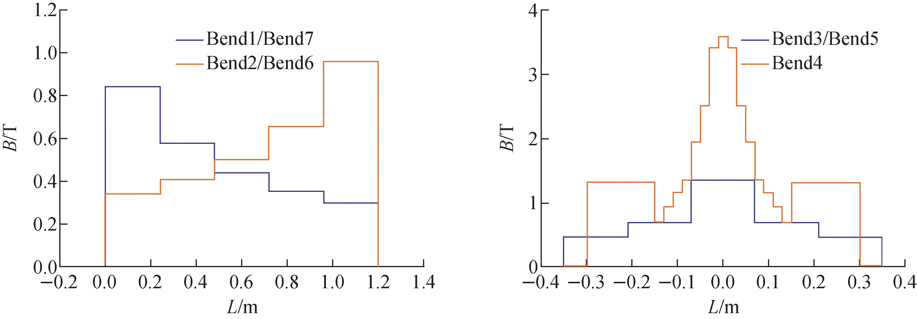
Fig.7 Magnetic field distribution of dipoles
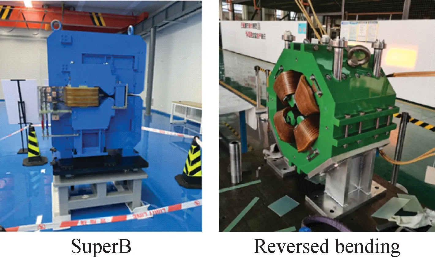
Fig.8 Prototypes of superB and reversed bending magnets
A prototype of superB magnet was built during the WHLS R & D, as shown in Fig.8. The highest magnetic field was reached 3.67 T and the field distribution of Bend 4 in Fig.7 is based on the measurement results of the prototype. We also built a prototype of the reversed bending magnet, just like a normal quadrupole which will be aligned about 12 mm off along the horizontal direction, as shown in Fig.8. More magnets prototypes are under construction now.
6 RF system
One BESSY type room temperature 500 MHz RF cavity and one third harmonic 1.5 GHz cavity will be installed in one 6.8 m straight section. The main parameters of the 500 MHz cavity are shown in Table 3. An aluminum 500 MHz RF cavity prototype was built during the R&D process, as shown in Fig.9. The test results of the prototype are well matched with the CST simulation results.
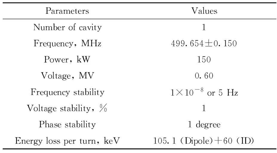
Table 3 Main parameters of RF systems
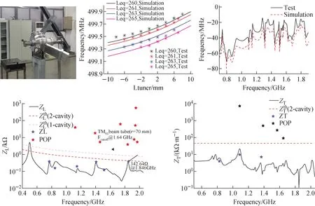
Fig.9 Prototype of aluminum RF cavity and its testing result
7 Injection and extraction system
The swap-out injection and extraction system will be installed in a straight section, as shown in Fig.10, and Table 4 shows the main parameters of the kicker. The kicker is using a strip line structure, which was successfully designed and manufactured in ALS-U[12], APS-U[13]and HALS[14]. The septa include a 0.6 m, 120 mrad DC septum and a 0.4 m, 40 mrad, 100 μs half-sin waveform in-vacuum septum.
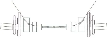
Fig.10 Injection and extraction system layout
8 1.5 GeV linac injector
To combine current requirement and future development, a full-energy LINAC will serve as the injector of the 1.5 GeV storage ring. Swap-out injection is chosen due to very small dynamic aperture of the diffraction-limited storage ring. This requires that the LINAC must provide a high single bunch charge up to 1.7 nC to achieve the design current of 500 mA in the storage ring, and 1.0 nC for 300 mA. Meanwhile, there are high requirements for beam emittance, energy spread and beam stability to give sufficient injection efficiency. In order to retain the potential of driving a free electron laser (FEL) by extending the LINAC in the future, installation spaces of laser heater (LH), bunch compressor (BC) and beam diagnostic instrumentations are carefully considered and reserved in the beamline design of the LINAC.
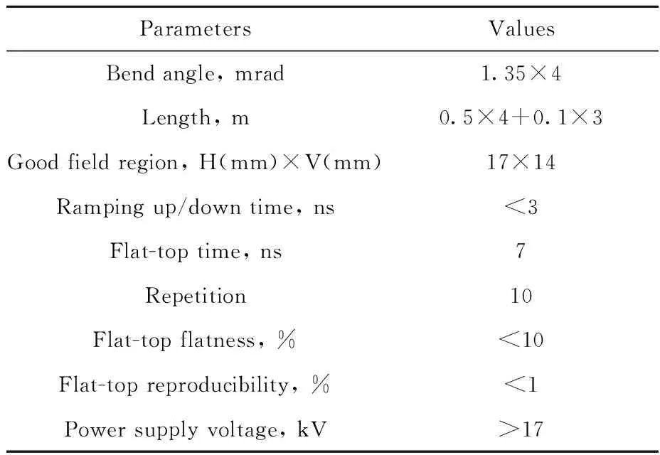
Table 4 Main parameters of kickers
8.1 Physics design of the LINAC
Design layout of the 1.5 GeV LINAC is shown in Fig.11. Main beam parameters are listed in Table 5. The LINAC is mainly composed of an electron gun, several acceleration structures, focusing magnets, beam diagnostics and so on. To ensure the beam quality and a bunch charge as high as 1-2 nC simultaneously, it is planned to use a photoinjector with high-quantum-efficiency semiconductor photocathode[15]. To mitigate wakefield caused by high bunch charge, S-band cavities with large inner aperture are considered as the main acceleration structures[16]. The 100 MeV injector of the LINAC mainly consists of a RF gun, a focusing coil for emittance compensation, two 3 m long constant-gradient travelling-wave acceleration tubes working at 2 998 MHz. The main acceleration section downstream is composed of 14 RF units. Each of them has two acceleration tubes. Between the 100 MeV injector and the main acceleration section, about 5 m of space is reserved for installation of the laser heater in the FEL phase. At the same time, a 15 m long beam drift is reserved at about 300 MeV in the main acceleration section for installation of the bunch compressor in the future. Quadrupole triplets are used as transverse focusing elements before 300 MeV, and then FODO structures are applied. To have sufficient experimental space and upgrade potential, beamline from the gun to the injection point of the 1.5 GeV storage ring is designed to be about 200 meters long.

Fig.11 Design layout of 1.5 GeV LINAC
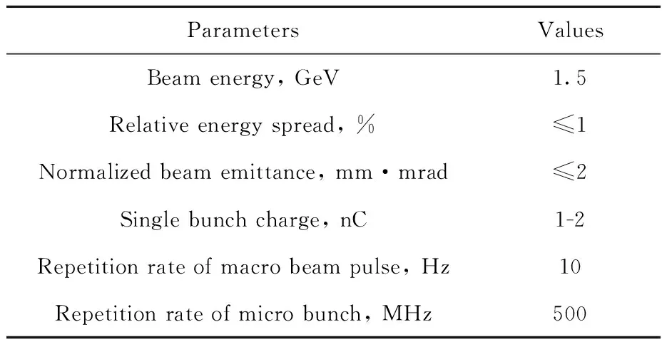
Table 5 Main beam parameters of 1.5 GeV LINAC
8.2 100 MeV injector for the LINAC
For the interest of beam manipulation and commissioning, three independent klystrons are used to provide high-power RF pulses for the 2 998 MHz electron gun and two acceleration structures in the 100 MeV injector of the LINAC, respectively. The 1.6 cell RF gun adopts semiconductor photocathode with high quantum efficiency that is excited by dedicated driving laser system[17]. The well-known beam dynamics simulation software ASTRA has been used to design the beam physics and optimize the emittance compensation of the injector. The required field data of the gun, the focusing coil and the acceleration tubes are calculated by electromagnetic software such as SUPERFISH and CST. The beam dynamics optimization of the injector is a multi-dimensional iterative scanning process of various hardware parameters. Therefore, multi-objective genetic algorithm (MOGA)[18]optimization of the beam dynamics has been applied in the design, including pulse shape of the driving laser, RF field gradient and phase of the electron gun and acceleration cavities, magnetic field profile and strength of the focusing coil, locations of these components and so on. Main working parameters of the injector and evolution process of the beam along the transport direction after beam dynamics optimization are shown in Table 6 and Fig.12, respectively, when the bunch charge is 1 nC. After optimization, a transverse normalized emittance below 1 mm·mrad has been achieved at a beam energy of 100 MeV, while the relative energy spread is about 0.4%.
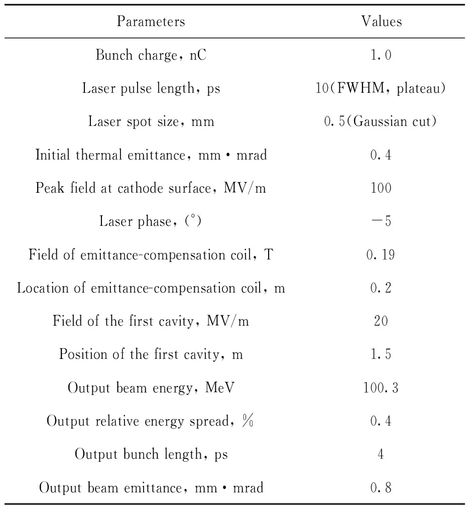
Table 6 Main parameters of 100 MeV injector
9 Future plan
WHLS phase Ⅰ project is planned to start in near future. A prototype of half standard cell, which includes all magnets, vacuum systems with at least 3 BPMs, girders and power supplies, will be built this year. In the meantime, a copper RF cavity with solid state amplifier and LLRF, a strip line kicker system and a photocathode gun will be developed, too. The whole project will be constructed in about 4 years.
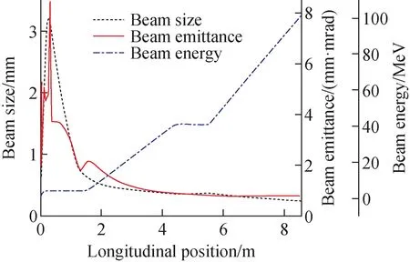
Fig.12 Typical beam parameters along 100 MeV injector
