中红外波段As2S3 光子晶体光纤中受激布里渊散射的研究
2022-09-07孙慧杰侯尚林雷景丽
孙慧杰,侯尚林,雷景丽
(兰州理工大学 理学院, 甘肃 兰州 730050)
1 Introduction
Capacity expansion through dense wavelength division multiplexing[1-3], frequency division multiplexing[4-5], time division multiplexing[6-7]and space division multiplexing[8-9]in the conventional 1.55 μm telecom band has been extensively investigated.These technologies utilize a limited spectrum to achieve high-speed, high-capacity information transmission, and they will be more efficient if their available spectrum can be further extended. For this reason, a series of studies have been conducted to find new communication windows outside the 1.55 μm telecommunication waveband[10-11]. In addition to communication purposes, optical fibers operating in the infrared band have many potential applications in chemistry, stress and temperature sensing[12-15]. Several commonly used materials for the fabrication of optical fibers operating in the m id-infrared spectrum range include chalcogenide[16-18], tellurite[19], high germania-doped[20]and fluoride[21]glasses. The main advantages of these glasses over the widely used silica glasses are that they have lower losses in the mid-infrared band, while chalcogenide glasses have higher nonlinear coefficients.
Chalcogenide glass such as As2S3with low optical loss and high nonlinearity is a good candidate for optical communication and optical sensing in the m id-infrared waveband. As2S3bulk samples transmit light in the 0.6-12 μm spectrum range while the transparency window for As2S3fiber is significantly narrower at 1-6 μm[12]. The definition of the infrared wavelength range varies with the applicable discipline or application scenario. In this paper, we consider 0.7-2 μm as near-infrared, 2-15 μm as mid-infrared, and 15 μm-1 mm as far-infrared. To date, several studies of Stimulated Brillouin Scattering (SBS) based on As2S3materials have been reported where SBS in various As2S3fibers were explored experimentally and theoretically. Kentaet al.[22]studied SBS in a multimode As2S3fiber using a Nd:YAG pulsed laser operated at 1.064 μm.Xuet al.[17]numerically analyzed SBS in As2S3suspended-core Microstructured Optical Fibers (MOFs),then the circumstances when the holes of the MOFs were filled with trichloromethane, ethanol and water were further investigated. SBS-induced slow light in an As2S3fiber is also a promising application. Floreaet al.[18]demonstrated for the first time that by using a slow-light generation in single mode As2S3fiber, they could obtain a delay of 19 ns in 10 m of fiber with only 31 mW of launched power,then a temperature sensor using SBS-based slow light was proposed by Mbayeet al.[23]. Experimental characterization of SBS at 2 μm in an As2S3stepindex fiber was reported by Derohet al.[10]. When pumping at 2 μm, the Brillouin Frequency Shift(BFS) from the As2S3step-index fiber is around 6.2 GHz , which is almost the same as the BFS from the As2S3Photonic Crystal Fiber (PCF) proposed in this paper.
We report novel As2S3PCFs with square arranged air holes. The SBS of the proposed fibers at mid-infrared waveband were theoretically investigated and their mode contributions were analyzed.The BFS, Brillouin threshold and Brillouin Gain Spectrum (BGS) were simulated by the finite element method. This work is of great significance for the design and fabrication of optical devices or optical sensors at the mid infrared waveband.
2 Model and theory
Fig. 1. shows the cross section of the proposed PCF which is made entirely of pure As2S3with square arranged air holes. The cladding consists of two layers of square air holes and three layers of regular octagonal air holes arranged in a square lattice across the cross section. There is an absence of square air holes in the center, which serves as the core of the PCF. Unlike the popular circular air holes, the use of square and octagonal air holes allows the fiber core to be square so that a square optical mode can be obtained. In Fig. 1,Ddescribes the circular diameter of the octagonal air holes,Λis the pitch of the air holes andAis the edge length of the square and octagonal air holes. In this work, the side lengths of the square air holes and the regular octagonal air holes are fixed to 3 μm and the diameter of the cladding is 125 μm. We define the factorD/Λas the Air Filling Fraction (AFF) to identify PCFs with different structural parameters.
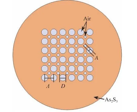
Fig. 1 The cross-section of the As2S3 PCF
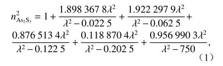
The refractive index of As2S3as a function of wavelength which is derived from the Sellmeier equation[24]as whereλis the wavelength in microns andnAs2S3is the refractive index of As2S3. The other material properties such as densityρ, Young’s modulusY,Poisson’s ratioνpand the Photo-elastic tensor of As2S3are shown in Table 1[25].
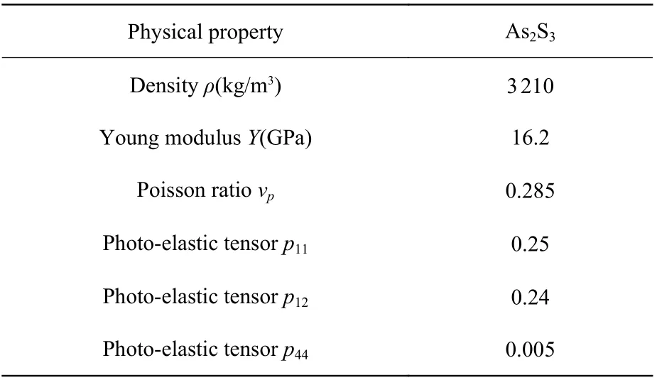
Tab. 1 Material parameters of As2S3
In our proposed PCF, because of the influence of air holes on the cladding, the cladding’s effective refractive index is lower than that of the core, which forms a total internal reflection waveguide structure.According to the optical waveguide theory, the normalized frequency is determined by[27]:

whereλpis the pump wavelength,reffis the effective core radius andnFSMis the refractive index of the fundamental space filling mode (FSM). It is well known that the normalized frequency is an important parameter to determine the cut-off condition.When the normalized frequency is lower than 2.405,the high-order optical modes in the fiber are cut off.
SBS is a typical third order nonlinear optical phenomenon. Its characteristic is that the energy of the pump wave is transferred to a Stokes wave through an acoustic wave. The acoustic wave is driven by the electrostrictive force generated by the beating between the pump and Stokes waves. The acoustic waves periodically modulate the refractive index of the medium to obtain characteristics similar to those of fiber Bragg gratings. However, unlike fiber Bragg gratings, since the acoustic wave moves along the fiber, the Doppler effect will creat a red shift in the reflected wave.
The spatial distribution of acoustic modes can be obtained from the wave equation[28]
whereu(x,y) is the spatial distribution of the acoustic mode andβadenotes the propagation constant of the acoustic wave. Here,βasatisfies the phase matching conditionβa=2β0for backward SBS,β0=2 πneあ/λ is the propagation constant of the optical mode,neffis the effective refractive index of the optical mode. The BFS of each acoustic mode corresponds to its acoustic frequencyfB. Since the longitudinal acoustic waves play a dominant role in PCF, the transverse acoustic waves are not taken into account. Therefore the simulation in this paper is valid only for longitudinal acoustic modes.
When the attenuation of an acoustic wave with timetfollows exp(-t/τ), the BGS has a Lorentzian spectral profile which is expressed as[29]
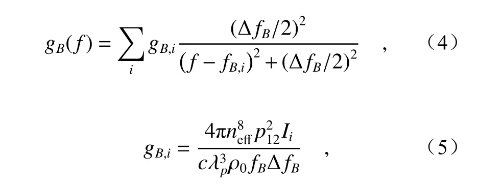
wheregB,iis the peak value of the Brillouin gain for each acoustic mode and ΔfBis the Full Width at Half Maximum (FWHM) of the gain spectrum which is related to the phonon lifetime τ by ΔfB=(2πτ)-1. For As2S3, the phonon lifetime is 1.33 ns at a pump wavelength of 1.064 μm, and the phonon lifetime of the acoustic wave in an SBS is proportional to the square of the pump wavelength[30]. The overlap integralIiis introduced to characterize the interaction strength between acoustic modes and optical modes.Iican be expressed by the integral on the fiber cross section as[29]
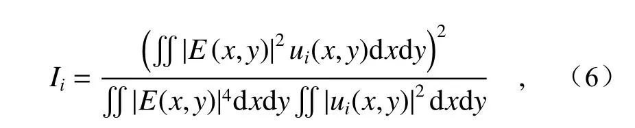
whereE(x,y) andui(x,y) are the spatial distribution of the optical andith-order acoustic mode, respectively.
In SBS, the effective optical mode area is another key factor. It has a significant effect on the Brillouin gain and Brillouin threshold. Both the core size andnFSMwill affectAeffsignificantly.Aeffis obtained using
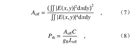
wherePthandLeffis the Brillouin threshold power and the effective fiber length, respectively. Note that,Cin Eq. (8) changes with different types of fiber, e.g. in standard single-mode fibersCequals 21[29]. However, in the As2S3PCF proposed in this paper, the value ofCneeds to be further explored.Nevertheless, we can compare the relative Brillouin thresholds for PCFs with different AFFs or at different pumping wavelengths.
3 Results and discussion
Five PCFs with different structures of varying air hole pitches were calculated, and their AFFs were 0.5, 0.6, 0.7, 0.8 and 0.9, respectively. Fig. 2 shows the simulated results of Fundamental Optical Modes (FOMs) with different AFFs at pump wavelengths of 2 μm, 4 μm and 6 μm, respectively.Since the PCF core is a square area, the distribution of the FOM approximates a square when the four regular octagonal air holes closest to the center are aligned.
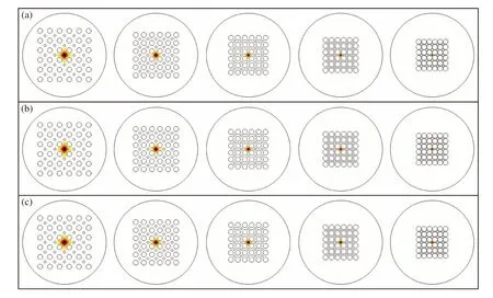
Fig. 2 Spatial distributions of FOMs with different AFFs at pump wavelengths of (a) 2 μm, (b) 4 μm and (c) 6 μm
PCFs with larger AFFs have a better ability to confine optical waves and their optical fields are more concentrated. The core sizes of PCFs with different AFFs are significantly different. PCFs with larger AFFs have smaller core sizes, which has the largest impact on their effective mode areas. Their effective mode areas vary linearly with the pump wavelength due to the fact that light with a longer wavelength is less likely to be confined in the core and is negatively correlated with the AFF as shown in Fig. 3 (Color online).
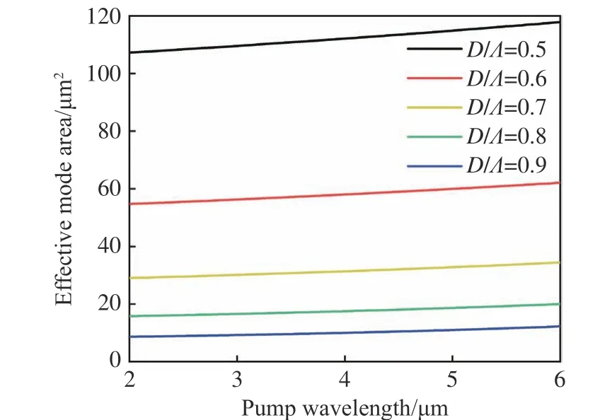
Fig. 3 The effective mode area of FOMs with different AFFs at pump wavelength from 2 μm to 6 μm.
To determine the condition of single mode transmission, the refractive index of the FSM was also calculated to obtain the normalized frequency.Fig. 4(a) (Color online) is the spatial distribution of the FSM which is the fundamental solution of Maxwell’s wave equation in the cladding. Fig. 4(b) (Color online) is the refractive index of FSM with different AFFs versus the pump wavelength.
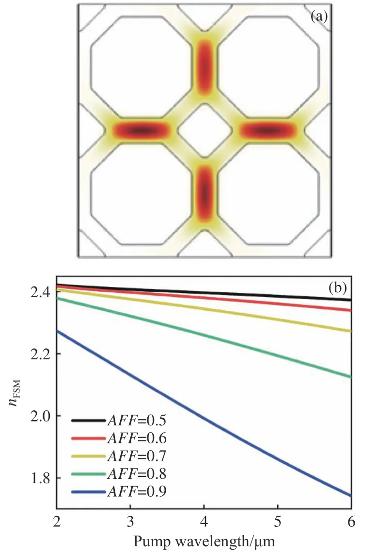
Fig. 4 (a) The spatial distribution of the FSM. (b) The dispersion of the refractive index of FSMs with different AFFs
Then, the normalized frequency can be obtained using Eq. (2) as shown in Fig. 5 (Color online). The dashed line in the figure corresponds to the normalized frequency of 2.405, which is the dividing line between single-mode operation and multimode operation. Only those below the dashed line,i.e. PCFs with AFFs less than 0.6, can maintain single-mode operation in the 2 μm to 6 μm waveband.
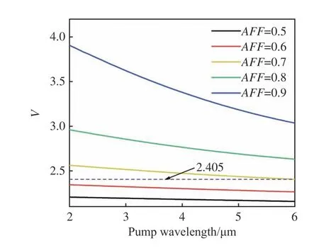
Fig. 5 The normalized frequency V versus pump wavelengths at different AFFs
The effective refractive index of FOMs with different AFFs is shown in Fig. 6 (Color online). As the pump wavelength increases, the effective refractive index of FOMs decreases, which is a joint effect of their waveguide properties and material dispersion. When the PCF has a large AFF, the effect of the PCF structure on the change in the effective refractive index is more obvious when the pump wavelength is changed.
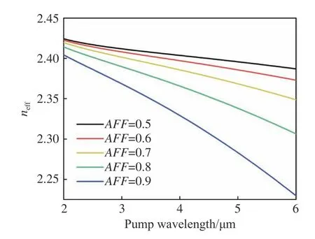
Fig. 6 The effective refractive index of FOMs with different AFFs at pump wavelengths from 2 μm to 6 μm.
In single-mode fibers, the BGS will have multiple peaks due to their higher-order acoustic modes,but in multimode fibers, the BGS becomes more complex under the influence of higher-order optical modes. The mode composition of the pump and Stokes pair will also have an impact on the BGS.Therefore, in this paper, only SBS in single-mode PCF was discussed.
The propagation constants of the acoustic modes are obtained using the phase-matching condition and Eq. (3) are solved by the finite element method. Fig. 7 (Color online) shows the spatial distributions of the acoustic modes at various pump wavelengths with AFFs of 0.5 and 0.6. For each situation, three acoustic modes with the largest overlap integral for different pump wavelengths and AFF are illustrated. All the acoustic modes shown in Fig. 7 belong to the symmetric L0m-like acoustic modes group since the overlap integrals between the antisymmetric acoustic modes and FOMs are almost zero and their contributions to SBS are negligible.
Fig. 8 (Color online) illustrates the BGS of the PCF with an AFF of 0.5 at a pump wavelength of 6 μm. The primary peak of the BGS is mainly generated by the interaction between the acoustic mode and FOM while the higher-order acoustic modes have higher frequencies to bring some distortion to the edge of the primary peak. The Brillouin gain generated by the L01-like acoustic mode is 14.7 dB and 19.4 dB greater than that generated by the L02-like acoustic mode and L03-like acoustic mode, respectively. The FWHM of the BGS is 3.8 MHz and the BFS corresponding to the L01-like acoustic mode is 7.21 MHz and 16.6 MHz smaller than that corresponding to the L02-like and L03-like acoustic modes,respectively.
When using shorter pump wavelength, for example, Fig. 9 (Color online) presents the BGS in PCF with an AFF of 0.5 at 2 μm pumping wavelength. The BFS generated by the L01-like acoustic mode are only 2.3 MHz and 4.1 MHz smaller than that generated by the L02-like and L03-like acoustic modes, and the frequency difference between them is too small to be separated in the BGS at an FWHM of 33.9 MHz for each gain peak. The Brillouin gain generated by the L01-like acoustic mode is 13.8 dB and 25.9 dB greater than that generated by the L02-like acoustic mode and L03-like acoustic mode, respectively. Therefore, the BGS in single-mode PCF is generated by the interaction between the L01-like acoustic mode and the FOM, while the effect of higher-order acoustic modes on the BGS is almost negligible.
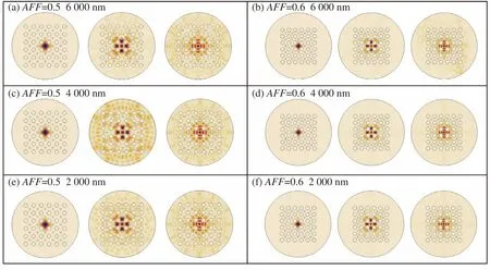
Fig. 7 Spatial distributions of acoustic modes with different AFFs and pump wavelengths. The acoustic modes in each case in the figure are L01-like, L02-like and L03-like modes from left to right
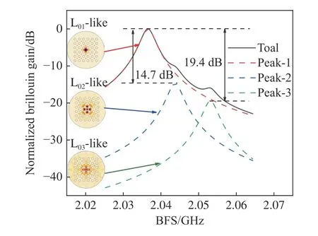
Fig. 8 BGS at an AFF of 0.5 and a pump wavelength of 6 μm
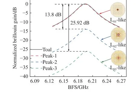
Fig. 9 BGS at an AFF of 0.5 and a pump wavelength of 2 μm
The BGS of PCFs with AFFs of 0.5 and 0.6 at different pump wavelengths are shown in Fig. 10(a)(Color online) and Fig. 10(b) (Color online), respectively. Since the acoustic frequencies are lower and have higher phonon lifetimes when pumped with longer wavelengths, the gain spectra are correspondingly narrower, which is evident in Fig. 10.The FWHM of the BGS is nine times wider at a pump wavelength of 2 μm than that at a pump wavelength of 6 μm. Since the effect of structure on BFS is not very drastic, the BFSs differences of PCF with different AFFs are megahertz orders of magnitude at each pump wavelength which is relatively small. In the 2 μm to 6 μm waveband studied in this paper, the maximum Brillouin gain of PCFs with AFFs of 0.5 and 0.6 are 2.413×10⁻¹⁰m/W and 2.429×10⁻¹⁰m/W, respectively.
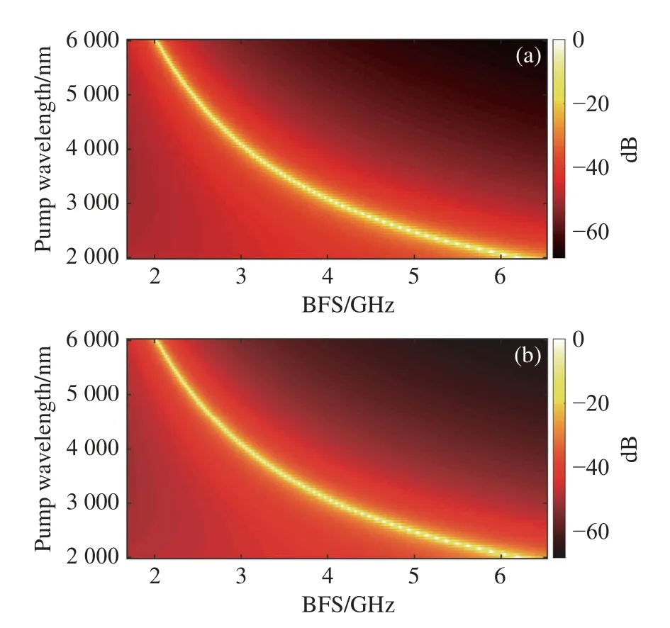
Fig. 10 The BGS for interaction between the L01-like acoustic mode and the FOM as a function of pump wavelength for PCF with an AFF of (a) 0.5 and (b) 0.6. The 0 dB in (a) and (b) respectively correspond to 2.413×10⁻¹⁰ m/W and 2.429×10⁻¹⁰ m/W.
The relative Brillouin threshold was estimated using Eq. (8) as shown in Fig. 11. The relative Brillouin thresholds obtained by normalization can be used to compare the Brillouin thresholds at PCFs with different AFFs or at different pump wavelengths. The PCF with an AFF of 0.6 has a significantly lower Brillouin threshold than the PCF with an AFF of 0.5 owing to its smaller area of optical modes. For a particular fiber structure, the Brillouin threshold is smaller when using shorter pump wavelengths than when using longer pump wavelengths. When the same effective length of fiber is available, the Brillouin thresholds are 27.8%and 19.6% larger at a pump wavelength of 6 μm than that at a pump wavelength of 2 μm in the proposed fibers with AFFs of 0.5 and 0.6, respectively.
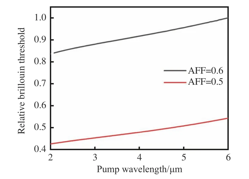
Fig. 11 The relative Brillouin threshold for PCFs with AFFs of 0.5 and 0.6 versus the pump wavelength.
4 Conclusion
In summary, an As2S3PCF was proposed. Its single-mode conditions were explored and its SBS properties including BFS, Brillouin gain coefficients, BGS and Brillouin threshold were investigated. According to our calculations, among our proposed fibers, only those with AFFs of 0.5 and 0.6 can realize single mode transmission in the 2 μm to 6 μm waveband. The contribution of higher-order acoustic modes to the BGS in single-mode PCF is weak, and only the L01-like acoustic mode is feasible. The maximum Brillouin gain coefficients in the PCFs with AFFs of 0.5 and 0.6 at the pump wavelengths of 2 μm to 6 μm are 2.413×10⁻¹⁰m/W and 2.429×10⁻¹⁰m/W, respectively. This work has implications for the design and fabrication of SBSbased all-optical devices in the mid-infrared waveband.