Optical fiber FBG linear sensing systems for the on-line monitoring of airborne high temperature air duct leakage
2022-08-31QinyuWang王沁宇XinglinTong童杏林CuiZhang张翠ChengweiDeng邓承伟SiyuXu许思宇andJingchuangWei魏敬闯
Qinyu Wang(王沁宇) Xinglin Tong(童杏林) Cui Zhang(张翠)Chengwei Deng(邓承伟) Siyu Xu(许思宇) and Jingchuang Wei(魏敬闯)
1School of Information Engineering,Wuhan University of Technology,Wuhan 430070,China
2National Engineering Laboratory for Fiber Optic Sensing Technology,Wuhan University of Technology,Wuhan 430070,China
Keywords: gating array,quasi-distributed measurement,temperature monitoring,prague grating,miniaturization
1. Introduction
As modern science and technology research continues to expand, especially in connection to aerospace vehicles and modern aircraft applications,[1]the development trend is one that centers upon an intelligent, self-aware, safe, and economically viable new generation of aircraft. Prediction and health management systems for aircraft are key technologies to improve aircraft reliability, testability, security and maintenance.[2]
An important part of the aircraft is the health management system, since it plays an important role in the temperature monitoring of the aircraft ducts, engines and other key components.[3]The U.S. military standard, MIL-87145 regulations require, in order to protect aircraft from any damage caused by high temperature gas,that an efficient air leakage detection system is fitted.[4–7]When catheters under high temperatures are present in the engine compartment, hanger,wing, wheel wall and environmental control system equipment compartment, etc., they should be monitored by ensuring that there is sufficient air leakage detection. Wire insulation, commonly used in aircraft equipment compartments, is often the least temperature-resistant material, and in the sections where they exist,176◦C is generally the allowable upper limit temperature.[8]If the air transported by the catheter is at or above this temperature, the catheter should contain a leak detection system.[9]
There are three main types of temperature detectors used on board an aircraft: thermistor temperature sensor, the cocrystalline salt temperature detector, and the pneumatic temperature detector.[10]These sensors are relatively mature in development, but there are still obvious shortcomings in environmental adaptability and reliability, which include eutectic salt temperature detector realizing the temperature alarm based on its working principle,but without realizing the realtime temperature monitoring. The response time is 10 s,[11]the thermistor has poor linearity and low reliability, and can only represent the average temperature of the area, which is easy to report false alarm. The response time of 5 s[12]can only be achieved in an environment far exceeding the alarm temperature. The pneumatic temperature detector has a complex structure and poor stability. On the other hand,however,electric sensors are easily affected by electromagnetic interference that weakens its measurement accuracy,and they can also be safety hazards. Moreover, typical electronic temperature sensors are mostly point sensors,which are limited by thermal vacuum environments: monitoring of acoustic vibration parameters,as well as strain and pressure parameters at the limit temperature of a wide range of multi-point measurements[13]has yet to be achieved. Thus, a fully characterized performance of spacecraft is currently difficult to achieve. In addition,with the rapid development of aviation technology,the response time and false positive rate, and other key indicators in aircraft monitoring,the need for higher requirements is obvious.[14]
In terms of data acquisition, at present, such a system is based on a single chip microcomputer arm. The analogue-todigital (A/D) conversion of single chip microcomputer itself involves in and out interruptions,[15]which require a significant amount of time leading to a low conversion rate of the whole system. There are also data acquisition systems based on digital signal process(DSP).[16]The advantage is that it can closely combine front-end acquisition and back-end data processing. However,its programs in DSP cannot be executed in parallel, so this type of acquisition system has disadvantages in terms of its acquisition speed. Although the data acquisition board,based on a bus,can greatly meet the requirements for experimental accuracy and speed,it is not conducive to the construction of small systems and it is expensive.[17]
Based on the above problems, to circumvent the bottleneck of health measurement technology of the existing sensing technology in airborne environment, the most important changes are the improvement of the integration of the system, the spatial resolution of the sensor and the seismic resistance of the sensor. On this basis, we can accurately locate the leakage position,detect the temperature,and provide a timely early warning. To achieve these aims, this paper proposes the stable distributed temperature monitoring of airborne high-temperature air duct by use of fiber Bragg grating wavelength division and time division multiplexing technology,alongside FBG grating array technology,which employs FPGA as the main control unit of the system, combined with an anti-vibration sensor packaging design.
2. System principles and design

Fig.1. System block diagram.
2.1. System key parameters
In a time-sharing system,the pulsed light source emits a light pulse signal (in which the pulse width is not important)into the fiber and it reflects a specific wavelength of the light signal when it reaches the grating. This is related to the position of the grating distanceτifrom the incident point

whereneis the effective refractive index of optical fiber andcis the speed of light in a vacuum.
In practical applications, the light pulse signal after the modulation has a certain width. If the time required for the signal to be transmitted between the two adjacent gratings on the optical fiber link is less than the width of the pulse, then the signal is reflected back by the adjacent two gratings and reaches the optical signal detector at the same time; thus it generates a signal crosstalk.However,signal demodulation errors and other problems are common,so the spacing between the two adjacent gratings must meet the need that the optical pulse transmission time is greater than the width of the optical signal. In order to achieve the time division in 1 m space distance,the output pulse width of the pulse light source must be less than 10 ns which ensures that the return signals do not overlap. Existing pulsed light sources are difficult to achieve this condition or require a more complex light source structure,which increases the system cost.[18]
2.2. System hardware design
The implementation of hardware logic includes three parts: the high-speed A/D conversion module,the data acquisition and storage module,and the data transmission module.The logic block diagram for the system hardware is given in Fig.2.
This system selects a frequency sweep pulse light source with a light source of 40 ns. According to calculations by using Eq.(1), a pulse light source less than 10 ns is required to meet the time division in 1 m space distance. Therefore, the required fine pulse width is generated by using a phase-locked frequency doubling and the phase configuration technology in FPGA. Next, the frequency is synthesized by use of a wide ranged pulse that is generated by the counter. A trigger 2 signal, with a pulse width of 5 ns and an amplitude of 3 V, is output as the trigger signal of the SOA and modulates the light source pulse.
Another circuit of trigger 1 is triggered, which becomes the light source. According to the requirements for light source triggering and the required trigger signal timing in Fig.3,the following parameters for the ready signal are used:1 µs, switch signal; 10 µs,T1; the time required for configuring the light source≥5µs,T2; holding time after the light source is stable≥1µs,Tdelay; and scanning interval≥1 ms.Therefore,the lowest trigger cycle of the light source is given by ready+T1+T2=7µs,and the trigger1 is set as the pulse signal with a frequency of 33 kHz, a pulse width of 1µs and an amplitude of 3.3 V.

Fig.2. Hardware logic block diagram.

Fig.3. Trig signal sequence diagram.
3. Grating array design
We employ a weak grating as the temperature grating,alongside the use of polyimide in the coating layer of the fiber optical grating that withstands high temperatures. This contrasts to the ordinary fiber optical grating, with acrylic resin as the coating layer that has degrading performance at high temperatures and ages more quickly. While our system has greater radiation resistance, stability and durability, etc.[19]It can also operate normally for a long period of time under a temperature of 300◦C[20,21]and four hours at 350◦C,meaning that it is suitable for use in high temperatures and harsh environments. There are two interlaced grating arrays,each of which is divided into three groups, as shown in Fig. 4. Each set is engraved with a total of ten different wavelength fiber gratings, denoted byλ1–λ10. The spacing between different wavelength gratings is 10 cm,identical wavelength spacing for adjacent grating arrays is 1 m,and any two grating arrays are displaced by 5 cm. To meet the requirements of a 3 m detection distance and 5 cm positioning accuracy,ten sets of different wavelengths for the gratings are accessed by wavelengths,and the gratings with the same wavelength are accessed by time.
趁田卓看博客的当儿,高潮禁不住想,我一出门,咋老是遇见诗人呢,把经历说给别人听,人家或许以为是我杜撰社交圈子以抬高自己的身份呢。事实上,高潮心里何尝不清楚,这年头,把随便什么文字分行来写的人,都自诩为诗人,诗人比街头上随处可见的练摊者都多呀。

Fig.4. System block diagram.
3.1. Sensor anti vibration package
To eliminate the cross-effect of stress on the temperature measurements,a side-by-side fiber is used to eliminate the effect of grating strain on such measurements. The naked fiber,coated with polyimide,is used as the force fiber,and the sensing fiber that is engraved with the fiber grating is employed as the stress-free fiber. The dispensing point is provided on the forced fiber. The grating spacing within the same grating array is set at 10 cm,and the sensing fibers engraved with both grating arrays are arranged in a 5 cm misalignment.Moreover,the same normal sensing fiber acts as the force fiber, and the starting and the up-wavelengths of the two grating arrays are displaced. We set a dispensing point at every 5 cm above the ordinary sensing fiber, and fix the forced fiber and the stressfree fiber at the dispensing point. The length of the stressfree sensing fiber, between the two adjacent fixed dispensing points, is equal to or greater than 101% of the length of the forced fiber. When there is an external stress, the ordinary fiber is straightened. As a result,the sensing fiber is still under a force,eliminating the cross-effect of stress.

Fig.5. Stress relief structure diagram of optical fiber sensor.

Fig.6. Sensor packaging design.
To ensure that the temperature measurements are accurate and the seismic resistance of the sensor is effective, a multilayer metal sleeve is selected for the packaging. The two-way fiber Bragg grating array is misaligned by 5 cm and it is adhered with a sufficient amount of high-temperature-resistant glue,then threaded into sleeve 3,and next both ends are sealed and fixed again with high-temperature-resistant glue. In addition, a sufficient amount of glue is adhered to the surface of casing 3 which is penetrated into casing 1, and the nanomagnesium oxide powder is filled between the gaps. Again both ends are sealed and fixed with high-temperature-resistant glue. The magnesium oxide powder can effectively prevent vibrations,it is flame retardant and has good thermal conductivity. In this structure,the grating is fixed in sleeve 1,and the grating receives a certain amount of tension when it traverses through sleeve 1. Magnesium oxide powder is filled between sleeves 1 and 3,which can effectively reduce the impact of the external vibrations on sleeve 3 and the internal gratings.
3.2. Sensor anti vibration package
We placed the sensor on a shaking table. During the experiment, we use the frequencies of 20 Hz, 60 Hz, 80 Hz,100 Hz,300 Hz,600 Hz,1000 Hz,and 1500 Hz. The change in the grating wavelength data is collected by the demodulator.After data processing,the results given by Fig.7 are obtained.

Fig.7. Variation of central wavelength at different vibration frequencies.
Under this packaging mode,low-frequency vibrations are shown to have a significant impact on the sensor, especially between 20–100 Hz. However, the overall fluctuation range is within 20 pm,which meets the necessary accuracy requirements.
4. System experiment and analysis
4.1. Grating array temperature calibration
Selecting the first set of 10 grilles,λ1−1–λ10−1, of the grating array to calibrate the temperature,we position this part of the sensor into the high temperature energy-saving tube furnace(which has a constant temperature accuracy of 1◦C).For every 25◦C, we need to wait for a constant furnace temperature over a one hour time period after each read of the temperature value. Taking the value of the central wavelength of the reflection spectrum,the central wavelength is recorded one by one,starting at room temperature and rising to 250◦C.On taking an average of three measurements,the resulting data is shown in Fig.8,and the linear fit curve parameters are shown in Table 1.
From the experimental temperature fitting curve, we can observe good linearity and sensitivity,and the ten gratings provide an average slope of the curve as 0.00995,which indicates that the temperature changes by 1◦C.The central wavelength drift of the grating is determined as 9.95 pm,and this value is consistent with the theoretical value category of wavelength–temperature 10 pm/◦C.
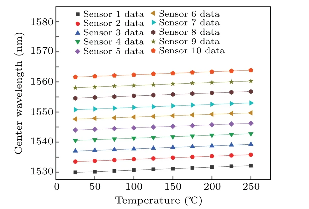
Fig.8. Fitting curve of sensor calibration.
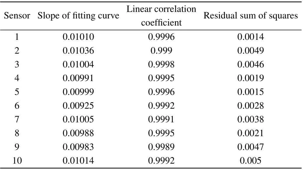
Table 1. Fitting curve parameters.
4.2. System principle verification
Following the set-up of the system,the light source scanning range is set from 1529 nm to 1562 nm, and a full band spectral signal is collected at a sampling rate of 500 M, as shown in Fig.9,corresponding to the ten central wavelengths,λ1–λ10. Each wave cluster contains a return signal for the same wavelength grating. The ordinates in the figure represent the code value of the intensity of the spectrogram,and the horizontal coordinates signify the number of sampling points.The selected grating reflectivity is 1%. In theory,the intensity of the reflective spectrum of each band should be close to this value,but may vary slightly due to the inconsistency of the reflectivity of the grating engraving process and the difference in grating performance that is caused by a certain intensity difference. The effect of the reflection spectrum intensity on the precision of the demodulation is reduced by a subsequent treatment,such as a spectral peak recombination and smoothing.
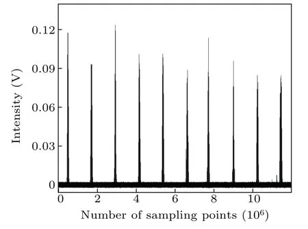
Fig.9. Full band spectrogram.
Each spectral expansion can provide the same wavelength segment spectral information. By select the larger 5th spectrum to enlarge,as shown in Fig.10,its effective grating spectroscopic signal in the timeline can be expanded to three different locations for the same wavelength grating information.The same wavelength grating physical spacing of 1 m is distinguishable according to the spectral information that is returned at different times.

Fig.10. Grating spectrogram for the same wavelength.
Extract the spectral information of the same wavelength gratingλ5at three different positions in the grating array and the spectral information of different wavelengthsλ1–λ10for splicing are shown in Figs.11 and 12. After fitting,the central wavelength and the error are shown in Table 2.

Fig.11. Spectrum mosaic for the same wavelength grating.
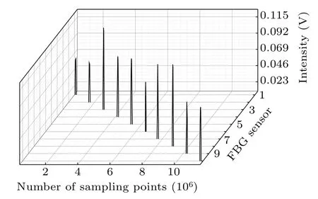
Fig.12. Spectrum mosaic for different wavelength gratings.
It can be seen from Fig. 13, by using theλ1–λ10grating center wavelengths and the same wavelengthλ5−1,λ5−2,andλ5−3, that the error of the grating center wavelength after fitting is less than 0±within 20 pm, and the feasibility of the time/wavelength division multiplexing is verified.Concurrently,the linear coefficient of temperature drift of 9.95 pm/◦C is obtained from the relationship between the temperature change and the grating center wavelength drift and the temperature calibration experiment.We can see that the measurement accuracy is within 2◦C,which meets the requirements for its efficient use in aircraft.
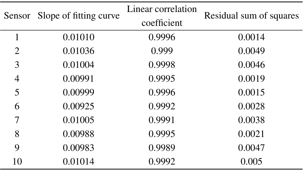
Table 2. Fitting error of the central wavelength.

Fig.13. Fitting error chart.
4.3. System warming experiment
As the system heats up, the wavelength of the thermal grating drifts backwards, as shown in Fig. 14. Moreover, the first grating with the same wavelength drifts backwards when altered by the temperature. Real-time temperature monitoring is obtained by fitting the demodulating of the drifted peak.
To verify the actual de-adjustment accuracy of the system when the temperature changes,we now design a working sensor for high temperature environments, as shown in Fig. 15.This is used to simulate the uniform flow of high temperature gas in the aircraft duct,and carry out experiments according to the requirements of field experiments(place any section of the fiber grating sensing probe in the airflow at a temperature of 300◦C±2◦C from room temperature, the exposure length is about 25.4 mm,the airflow diameter is 25.4 mm,and the distance between the fiber grating sensing probe and the airflow is 25.4 mm, and when it reaches 154◦C. The response time should not be greater than 10 s). One side of the catheter has 5 cm gaps between the leak hole,and the packaged sensor has clips fixed to the side that has the leakage pores, and there is grating point alignment with the holes.

Fig.14. Grating drift map after the heating.
In order to ensure the rationality of the simulated experimental environment, it is necessary to simulate and analyze whether the temperature at the outlet of the small hole can meet the experimental requirements. The fluid domain model shown in Fig. 16 is established. The diameter of the ventilation pipe is 60 cm,and there are 2.5 cm distributed mall holes as heat sources on the side of the pipe wall.
The simulated air pipe is fed with high temperature gas at 300◦C and a flow rate of 10 m/s, and the temperature distribution is shown in Fig.17.
The simulation results show that the average air temperature at the small hole is 287.67◦C,which is slightly lower than the input air temperature.When it is still higher than the actual temperature measurement range,it can be used as a simulated heat source.
When the gas temperature rises from 25◦C to 300◦C,the recording of the grating array 1(λ1−4)and 2(λ1−5)with the temperature values of multiple temperature points is applied and displayed on the computer after the demodulation of the system. A comparison between the demodulation data and the actual temperature is shown in Table 3.

Fig.15. Environmental simulation experiment.

Fig.16. Airway fluid domain model.

Fig.17. Tube body temperature distribution.

Table 3. Actual demodulation temperature error.
The demodulation error is essentially within 2◦C,which is consistent with the above experimental results,and the two adjacent gratings are fully distinguished within a 5 cm distance.
4.4. Temperature response time experiment
In order to simulate the actual leakage environment,place any section of the fiber grating sensor from room temperature in an airflow with a temperature of 300◦C±2◦C and a flow rate of 10 m/s,and test the response time to 154◦C.It can be seen from Table 4 that the response time to reach the warning temperature when the system is heating up does not exceed 4 s.

Table 4. Heating response time.
5. Conclusion
Part of keeping an aircraft safe involves the very important task of monitoring the aircraft’s hot air ducts. Traditional electrical sensors are susceptible to interference from the external environment, which means that the spatial resolution and accuracy of monitoring have certain limitations.As the demands on aircraft health monitoring increase,meeting these demands has gradually become more difficult. In this paper, we propose a high spatial resolution hot spot temperature detection system based on fiber Bragg grating arrays and a distributed high temperature sensor with better stability is designed for the complex use environment. The system adopts wavelength division/time division hybrid multiplexing technology, uses programmable logic gate array as the main control core,and adds semiconductor optical amplifiers to the system to realize extremely narrow optical pulse modulation and control. Our experiments show that the designed sensor can guarantee good stability under different vibration frequencies. The spatial resolution of the system temperature monitoring reaches 5 cm,the accuracy reaches 2◦C,and the alarm response time is within 4 s. It can not only meet long-distance and large-scale temperature detection, but also realize highprecision real-time monitoring,which is very suitable for aircraft health monitoring in complex environments.
杂志排行
Chinese Physics B的其它文章
- Direct measurement of two-qubit phononic entangled states via optomechanical interactions
- Inertial focusing and rotating characteristics of elliptical and rectangular particle pairs in channel flow
- Achieving ultracold Bose–Fermi mixture of 87Rb and 40K with dual dark magnetic-optical-trap
- New experimental measurement of natSe(n,γ)cross section between 1 eV to 1 keV at the CSNS Back-n facility
- Oscillation properties of matter–wave bright solitons in harmonic potentials
- Synchronously scrambled diffuse image encryption method based on a new cosine chaotic map
