Core structure and Peierls stress of the 90◦dislocation and the 60◦dislocation in aluminum investigated by the fully discrete Peierls model
2022-08-31HaoXiang向浩RuiWang王锐FengLinDeng邓凤麟andShaoFengWang王少峰
Hao Xiang(向浩) Rui Wang(王锐) Feng-Lin Deng(邓凤麟) and Shao-Feng Wang(王少峰)
1Department of Physics and Institute for Structure and Function,Chongqing University,Chongqing 401331,China
2CAS Key Laboratory of Magnetic Materials and Devices,Ningbo Institute of Materials Technology and Engineering,Chinese Academy of Sciences,Ningbo 315201,China
3Zhejiang Province Key Laboratory of Magnetic Materials and Application Technology,Ningbo Institute of Materials Technology and Engineering,Chinese Academy of Sciences,Ningbo 315201,China
Keywords: dislocation,temperature effect,aluminum
1. Introduction
Great efforts have been made to understanding the dislocation core structure and related properties,and much progress has been achieved before.[1–11]In experiment,several experimental techniques such as x-ray and neutron scattering,highresolution atomic force microscopy, advanced transmission electron microscopy are applied for probing dislocations core structure at the atomic scale.[3–6]This leads to directly imaging dislocation cores with single-atom sensitivity. Polymorphism of dislocation core structures at the atomic scale was predicted with a model and observed with bicrystal experiments and systematic atomic-resolution imaging.[5]The close match of predicted dislocation cores with direct imaging both geometrically and in quantity offers confidence that the modelling approach represents a reliable routine to pinpointing all core configurations for even a given dislocation type at the atomic scale.[5–8]While the core structures of dislocations are usually modeled and predicted from molecular dynamics simulations,[7–11]it is necessary to develop analytical theory adding a new dimension to understanding the properties of dislocations in real materials.
In 1940s, Peierls put forward a famous equation and obtained its exact solution that can reveal the characteristic size of dislocations and predict the strength of materials.[12,13]The equation is generally named as the Peierls equation and the related model is called the Peierls model or the Peierls–Nabarro(P–N)model.[1]In 1970s, Christian and Vitek suggested that the sinusoidal law in the P–N model should be replaced with the generalized stacking fault energy (γ-surface), which can be obtained directly from the interatomic interaction or from the first principle calculation.[14,15]In order to investigate dislocations with both edge and screw components, such as the dissociated dislocations in the face-centered-cubic (fcc) lattice, the original P–N model was extended to be a so-called 2D model in which the slip displacement is described by a two-dimensional vector.[16]If the change in space between two neighboring slip planes is not negligible, the 2D model should be further extended to a 3D model and in the same time theγsurface should be replaced by theγ-energy function(γ-potential).[17]Lejˇcek and Kroupa presented an equation for the screw dislocation with nonplanar 3-fold structure.[18]Based on Green’s formula for half-space and conformal mapping, Ngan derived the generaln-fold equation for nonplanar structure of the screw dislocation.[19]Wang and Hu found the exact dislocation solution of then-fold screw dislocation equation.[20]Merwe extended the Peierls–Nabarro theory to study the interface at which the lattice constant changes.[21–23]The P–N model combined with theγsurface has been widely used to investigate dislocations in a variety of materials.[24–29]
The conventional P–N model is characterized by a nonlinear integro-differential equation that is invariant under continuous translation transformation. Obviously, the lattice discreteness is not fully incorporated in the conventional P–N model. For instance, the Peierls barrier vanishes in the the continuum theory and thus dislocation as a topology defect can move freely if there is no ad hoc assumption. In order to evaluate the Peierls stress,one has to assume that the continuous envelope of the discrete slip field is always identical with the solution of the Peierls equation. A semidiscrete variational Peierls framework for dislocation core properties was developed early to investigate the narrow core dislocations in Si.[30]The fully discrete peierls equation was initially derived for a two-dimensional triangular lattice model that can be solved exactly.[31]Later, it was found that based on the spectrum analysis the fully discrete Peierls model can be established in a model-independent way.[32–34]The fully discrete Peierls model can accurately predict the core structure and explore dislocation response to the applied external loading.[34–36]In particular, the Peierls stress can be evaluated in a consistent way in the fully discrete Peierls model. Furthermore,the fully discrete Peierls model can reveal the new modes that appear only in the discrete systems. It is shown that when the lattice discreteness is fully considered, the core of a dislocation may further display various structures(polymorphism). Actually, every dislocation in the continuum theory always splits into two different types with different core.[33–37]The polymorphism of dislocation core structures at the atomic scale attracts much attention.[3,4,7,33–38]
Metal aluminum(Al)is widely used in modern engineering. The mechanical properties of aluminum such as plasticity and yield strength are mainly dominated by the core structure of an individual dislocation and the interaction between dislocations, or between dislocation and impurity.[1]Similar to other fcc metals,the most important dislocations in Al are the 90◦dislocation,the 60◦dislocation and the screw dislocation.These dislocations dissociate into two partial dislocations with a planar core confined to a{111}slip plane.[1,7–9,25,26,36,39–48]
The dislocation core and related properties are determined by crystal structure type and material mechanical features.Because mechanical features of a material are dependent on temperature,the core structure and related properties of dislocations are also temperature-dependent. It is significant to investigate what the influence of temperature on the dislocation is and how the dislocation properties change with temperature. The P–N model explicitly establishes the relationship among the dislocation core structure, the Peierls stress,the elastic constants and the generalized stacking fault energy(γ-surface). Therefore,if changes of the elastic constants and theγ-surface with temperature are known, temperature influence on the dislocation core and the Peierls stress can be predicted theoretically from the P–N model. Recently,the elastic constants andγsurface at finite temperature were calculated for Al from the electron density functional theory,and used to study the 90◦dislocation in the frame of the analytical P–N model.[29]Using the data presented in Ref. [29], authors investigated the evolution of the core structure and change of the Peierls stress with temperature.[36]It is found that for the screw dislocation there is stability transformation in the core structure as temperature increases,and the Peierls stress at the transformation temperature becomes remarkably smaller. A question naturally arises: what is the temperature influence on the core structures and the Peierls stress of the 90◦dislocation and the 60◦dislocation? In this paper,temperature effects on the core structure,core energy,and Peierls stress,etc.are comprehensively investigated for the 90◦dislocation and the 60◦dislocation using the fully discrete Peierls model. Instead of solving the conventional dislocation equation such as Ref.[29]addressed, the time-dependent dislocation equation (Landau equation) is used to study the equilibrium core structure, the structure relaxation,structure stability,and the motion of dislocations under applied stress field. The new method enables us to numerically obtain very accurate solution and precisely determine dislocation properties. The content is organized as follows. In Section 2,a brief introduction of the fully discrete Peierls model is given. In Sections 3 and 4,the core structure and the Peierls stress calculated from the fully discrete Peierls model are presented for the 90◦dislocation and the 60◦dislocation,respectively,in temperature range 0≤T ≤900 K.The temperature influence on the dislocation energy is discussed in Section 5. In Section 6,the stress field is evaluated and plotted for each kind of individual dislocation. In Section 7, the theoretical core structures at theT=0 K are verified by the first principle simulation. Finally,we summarize the results.
2. A brief introduction of the fully discrete Peierls model
Dislocations result from locally relative slip (mismatch or disregistry) between two neighboring lattice planes. The two lattice planes involved are usually referred to as the misfit planes. In order to make statement clear and definite, it is helpful to introduce the cut-plane that locates at the middle of two misfit planes and divides the crystal into two parts. The misfit plane above the cut-plane is named asa-plane and the misfit plane below the cut-plane is named asb-plane. The dislocation core structure is characterized by the slip (mismatch or disregistry)fieldSj(R)that is defined locally as the relative displacement between thea-plane andb-plane.For the straight dislocation,the dependence of two-dimensional lattice vectorRdegenerates into a function of a single variablelthat measures the distance from the dislocation center. In terms of the slip field, the energy functional (energy in a unit length) of a straight dislocation is[33,34,36]

whereSsandSeare the screw and edge components of the slip field, respectively,ρs(l)=Ss(l+1)−Ss(l) andρe(l)=Se(l+1)−Se(l)are the discrete dislocation densities,γ(Ss,Se)is the generalized stacking-fault energy (γ-surface),λis the step length defined by the distance between two neighboring lattice lines paralleled to the dislocation line,KsandKeare energy factors of the screw and edge dislocations,[1]βsandβeare the contact-interaction constants,[49]ψ(0)(z)is the Polygamma function. Generally, the energy given byUiis called the interaction energy (self energy) of the dislocation,or the elastic energy of the dislocation, and the energy given byUγis called the misfit energy. In the isotropic approximation,Ks=µandKe=µ/(1−ν),whereµis the shear modulus andνis Poisson’s ratio.
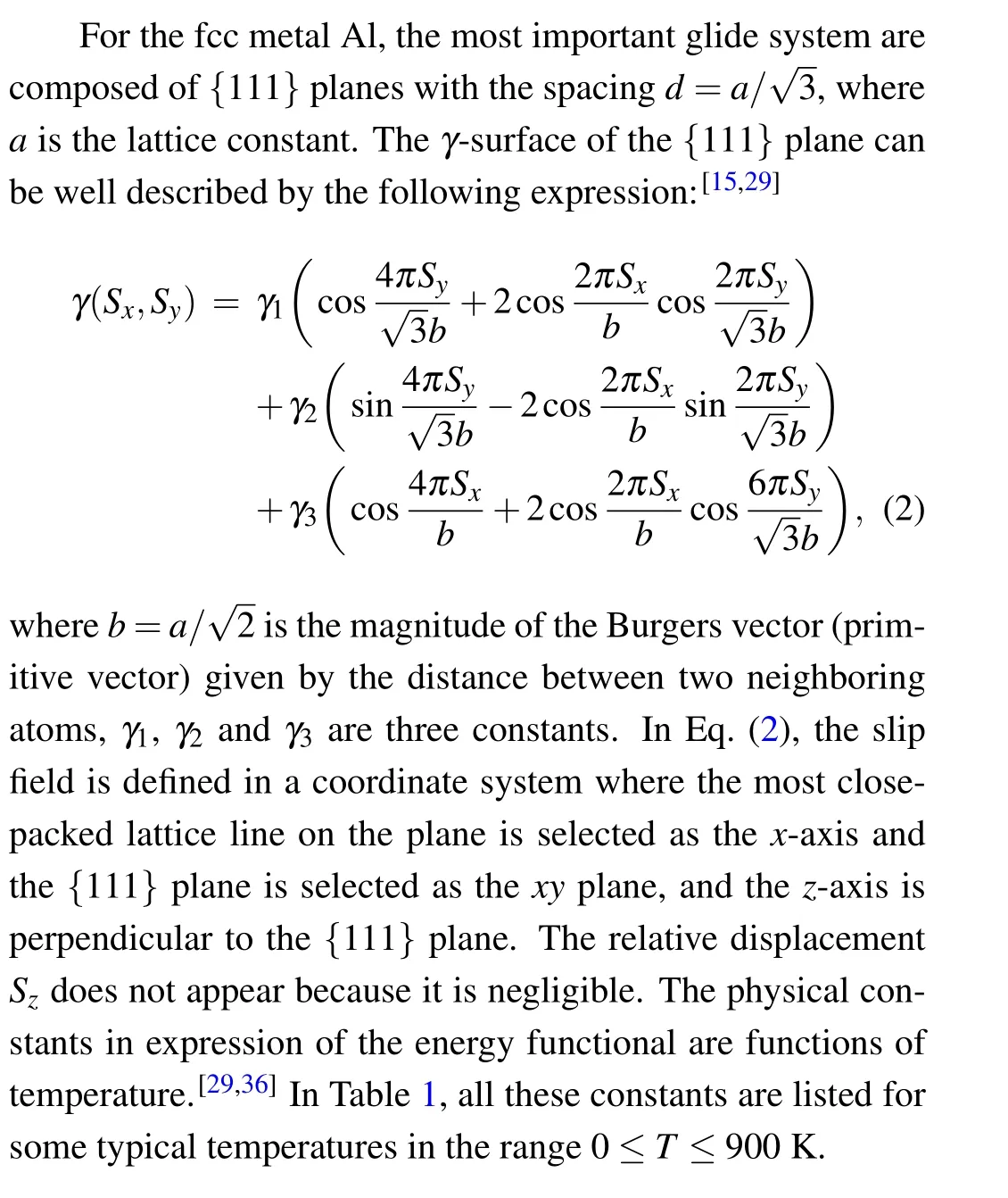
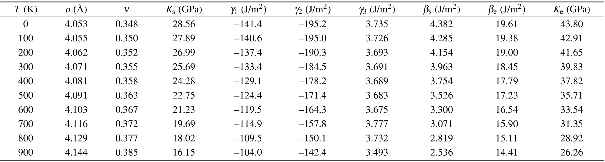
Table 1. The physical constants of metal aluminum.

whereΓis the effective damping constant. For mechanical processes there is a characteristic time,tc=a/ct, a ratio between the lattice constantaand the transverse wave velocityct. It is rational to take the damping time in the same order with the characteristic time
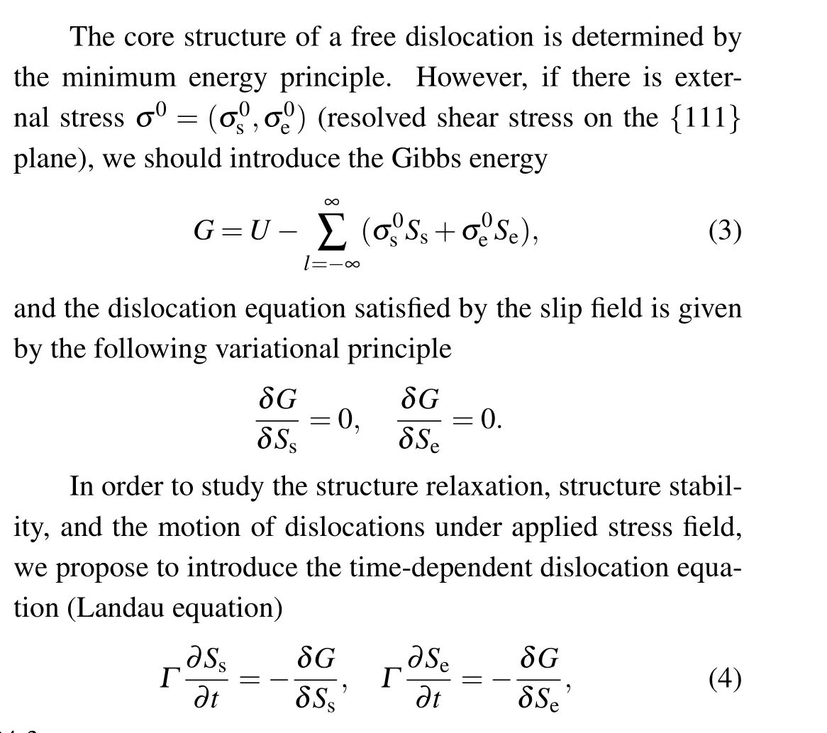
whereµ=Ksis the shear modulus. The exact value of the damping constant is of no great importance for the results obtained in this study. In the following,similar to the phase field theory of dislocations,[50]the time-dependent Landau equation is employed to obtain the equilibrium core and to determine the Peierls stress. As an efficient way, the stable equilibrium slip field can be obtained by relaxing an input solution with the asymptotic behavior given by the Peierls solution(boundary condition).[12,33]After the stable equilibrium slip field is obtained, the external stress field is applied gradually to explore how the dislocation responds. The Peierls stress is the critical stress at which the dislocation starts moving.

Fig. 1. The atomic configurations of the dissociated 90◦dislocation at T =0 K, where the empty circles and solid circles represent the atoms on the a-plane (above the cut plane) and the b-plane (below the cut plane), respectively. The symmetric-center line is marked by the solid line and the partial dislocations are marked by the dashed lines.

Fig.2.The atom configuration on the a-plane(solid circles)and b-plane(empty circles)for the 60◦dislocation)at T =0 K.The 60◦dislocation clearly dissociates into 30◦and 90◦partial dislocations separated by a small stacking fault band. The center of each partial dislocation is marked with a solid line.
3. The 90◦dislocation
The shear stress produced by the dislocation on the misfit plane (a-plane orb-plane) is evaluated and the results are shown in Fig. 4. The shear stress (σx) in the (edge) direction perpendicular to the dislocation line is nearly double of that(σy)along the(screw)parallel direction. At the positions of the partial dislocations the shear stressσxhas its maximum 0.1µ≈3 GPa.At the center of the dislocation,the shear stressσyhas the maximum 0.05µ ≈1.5 GPa. To examine the accuracy, the shear stress originated from theγ-surface is also evaluated. As shown in Fig. 4, two forces perfectly balance each other in our calculations. This implies that the solution obtained is very accurate.
The slip field and the density are plotted in Fig.5 for temperaturesT=0 K, 500 K, 800 K, 900 K. It is observed that the slip field and the related density change little as temperature increases. For the edge dislocation,temperature effect on the core structure is so weak that it can be neglected safely.

Fig.3. The slip field(a)and the dislocation density(b)of the 90◦dislocation at T =0 K.The edge component clearly splits into two partial dislocations(peaks)while the screw component shows feature of dislocation dipole. The calculated data(scatter points)can be well fitted by superpositions of dislocations [solid and dashed lines given by fitting Eqs.(6)and(7)].
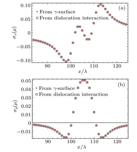
Fig.4. The shear stress(empty circles in(a)and(b))produced by the infinitesimal dislocation distribution on the misfit plane at T =0 K.The stress is precisely balanced by that resulting from the γ-surface (solid circles). The result indicates that the solution obtained is very accurate.
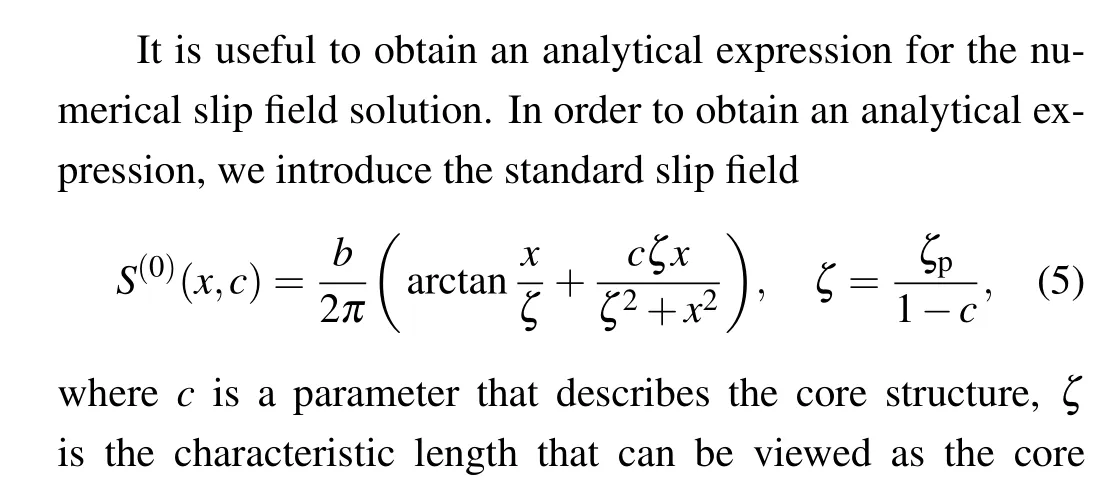

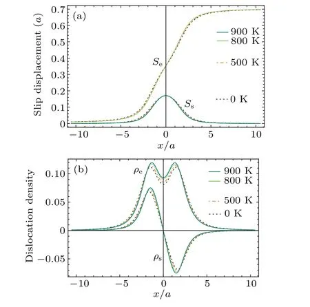
Fig.5. The slip field(a)and the dislocation density(b)along the Burgers vector direction at temperatures T =0 K,500 K,800 K,900 K.

In Table 2, the parametersc,ζ,c1,c2,ζ1,ζ2and the separation distancesDe,Dsare listed for various temperature.The largest effect of the temperature on the core structure focuses on the separation distanceDthat decreases with increasing temperature.
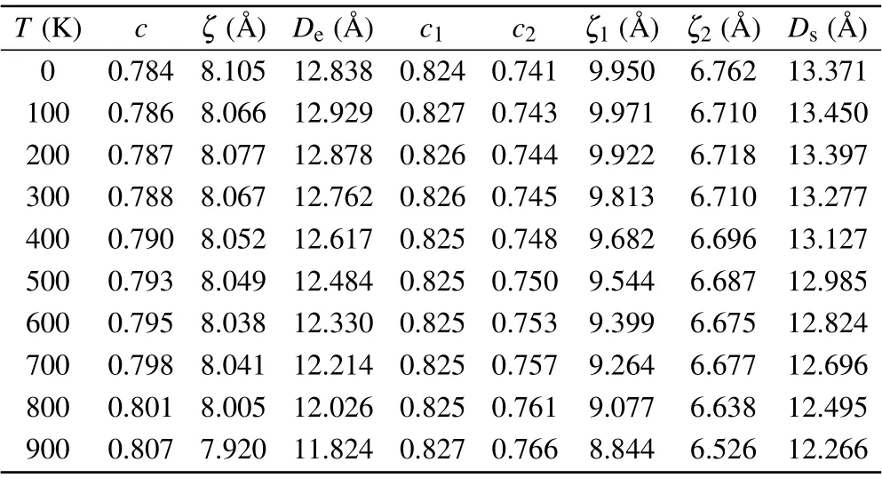
Table 2. The parameters in the fitting solutions of the edge dislocation.
In the fully discrete Peierls model, the Peierls stressσpcan be naturally evaluated without any ad hoc assumption.Applying an external stressσ0gradually, we can obtain the critical stressσ0=σp, at which the dislocation starts moving through crystal. For the 90◦dislocation, we find that the Peierls stress is so small that can hardly be observed in the numerical calculation. The upper limit is aboutσp<10−8µ ∼1 kPa. Such a small upper limit indicates that the Peierls stress nearly vanishes for the 90◦dislocation.

In the original P–N model,the width of an edge dislocation and the Peierls stress are given as follows:i.e.,the Peierls stress results from competition between the dislocation widthζand the step lengthλ.For the 90◦dislocation,it is reasonable to identify the widthζwith that appearing in the standard slip field Eq.(5). ForT=0 K,we haveζ ∼7 ˚A,λ ∼1.4 ˚A,andσp∼10−13µ. The Peierls stress is nearly zero for the 90◦dislocation indeed. This estimation qualitatively explains why the Peierls stress is so small for the 90◦dislocation.
4. The 60◦dislocation

whereφ=60◦is the angle between the dislocation line and Burger’s vector.
Replacing the edge and screw components(Se,Ss)in the evolution equation(4)by the parallel and perpendicular components(S‖,S⊥),we have the equation satisfied by the components(S‖,S⊥). Similarly,the stable dislocation solution of the equation can be automatically obtained by relaxing an input solution with the boundary condition

The slip field componentsS‖andS⊥are firstly evaluated at temperatureT=0 K for the 60◦dislocation. In Figs. 6 and 7, the slip field components in both the natural and intrinsic frame are plotted. We see that the density distribution of the screw component is compact while the density distribution of the edge component obviously dissociates into two parts. In Fig. 2, the atom configuration on thea-plane (solid circles)and theb-plane(empty circles)are explicitly plotted based on the slip field obtained. Apparently,the 60◦dislocation clearly dissociates into 30◦and 90◦partial dislocations separated by a small stacking fault band.

Fig.6. The fitting results of the numerical solution(scattered points)at T =0 K.The solid and dashed lines are from the fitting equations(10)and(12). From the density distribution(b), it can be seen that the 60◦dislocation splits into two asymmetric parts.
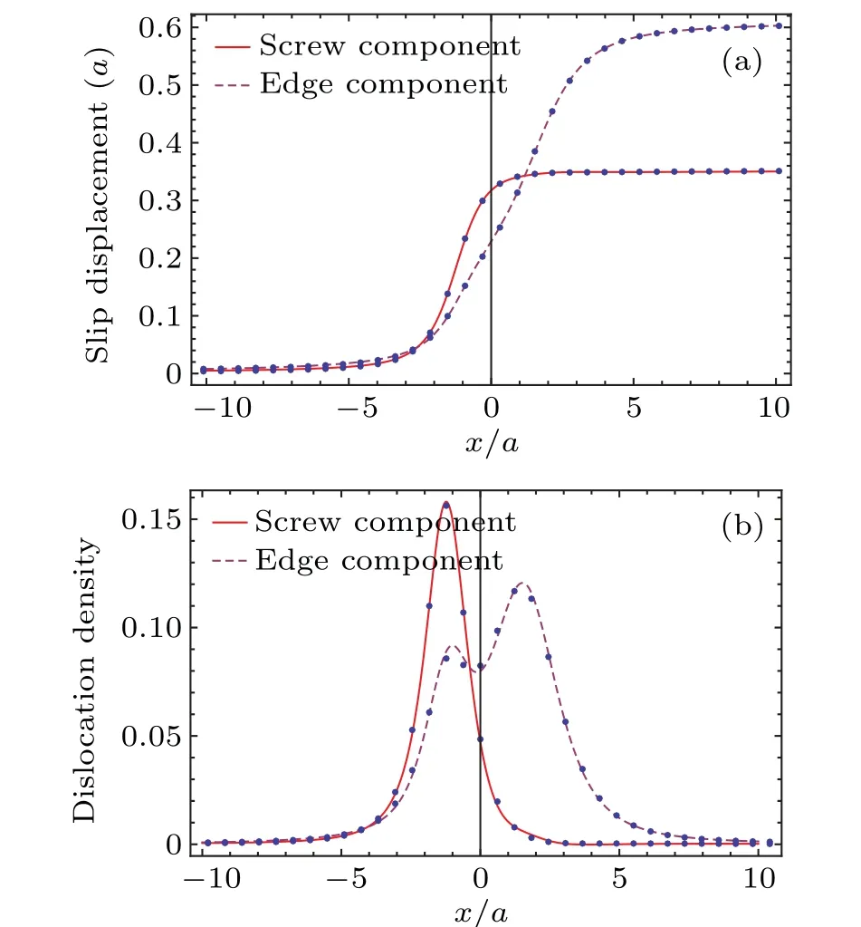
Fig.7.The slip field and density distribution of the edge component and screw component in the natural frame at T =0 K.From the density distribution(b),it can be seen that the screw component of 60◦dislocation is compact while the edge component dissociates obviously.
The shear stress produced by the dislocation on the mi sfti plane(a-plane orb-plane)is shown in Fig.8 forT=0 K.The stress distribution of the 60◦dislocation is not symmetric. Similar to the 90◦dislocation, the major shear stress results from the parallel slip (parallel to Burgers vector). The maximum shear stress is about 0.1µ ≈3 GPa that locates at the centers of the partial dislocations. The normal shear stress(perpendicular to Burgers vector)is about 0.6µ≈1.8 GPa. To verify the accuracy of the solution, the stress that originates from theγ-surface is also evaluated. As seen in Fig. 8, the shear stress produced by the dislocation is precisely balanced by that from theγ-surface.

Fig. 8. For the numerical solution of 60◦dislocation at T =0 K, the stress resulting from the γ-surface (solid circles) is precisely balanced by the stress resulting from the distribution of infinitesimal interactions(empty circles).
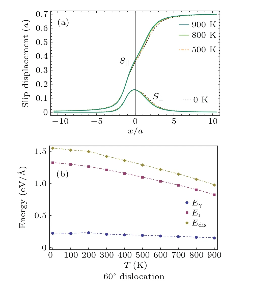
Fig.9. The slip field(a)and the dislocation energy(b)at temperatures T =0 K,500 K,800 K,900 K.
The slip field and the density are plotted in Fig. 9 for temperaturesT=0 K, 500 K, 800 K, 900 K. It is observed that similar to the edge dislocation the slip field and the related density change little as temperature increases. In Fig.10,the Peierls stressσpis plotted as a function of temperature.Surprisingly, the Peierls stress grows up monotonically from 1 MPa to 2 MPa as temperature increases from 0 K to 900 K.The order of the Peierls stress is same as the yield strength of Al observed in experiment.[54]The Peierls stress can also be estimated from Eq.(8). If the characteristic width is chosen to the smallest oneζ=4.735 ˚A andζ=4.271 ˚A(Table 5),respectively,forT=0 K andT=900,the Peierls stresses from Eq.(8)areσp=0.17 MPa andσp=0.4 MPa. The values are one order smaller than that obtained in our discrete model,but the increasing tendency with temperature is same.
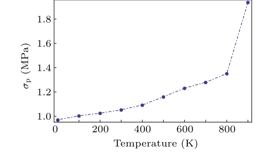
Fig.10. The Peierls stress as a function of temperature for the 60◦dislocation.

Due to the asymmetric core of 60◦dislocation,we need superposition of four partial dislocations (two partial dislocations plus two partial anti-dislocation)to fit the data. The fitting parameters are listed in Table 4.Figure 6 shows the fitting results of the numerical solution atT=0 K. The analytical expression is well coincided with the numerical solution. The two peaks in the dislocation density implies dissociation of the 60◦dislocation. The dissociation distance isD ≈11 ˚A.This value is slightly smaller than that(13 ˚A)of the 90◦dislocation,but much larger than that (4 ˚A) of the screw dislocation.[36]The splitting width obtained by atomistic simulation is∼10 ˚A.[55]From Tables 3 and 5, we see that the widths of partial dislocations slowly decrease as temperature increases. That is why the Peierls stress grows up with temperature.

Table 3. The fitting parameters for the parallel component of the slip field.
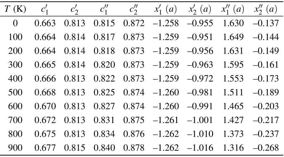
Table 4. The fitting parameters for the normal component of the slip field.

Table 5. The core widths and the separating distances of the partial dislocations.
5. The self-energy and the misfit energy
In theory, the dislocation energy consists of the interaction energy(self energy)of the infinitesimal dislocations and the misfit energy. The self energy and the misfit energy can be straightforwardly evaluated from the functionalUiandUγin Eq. (1) when the solution of the slip field is obtained. In Fig. 11, as a function of temperature, the self energyEiand the misfit energyEγare shown for the 90◦dislocation,the 60◦dislocation and the screw dislocation, respectively. The self energyEifalls off as temperature increase while the misfit energyEγhas a peak at temperatureT ∼200 K. In evaluation of the self energy, the logarithmic divergence is removed by truncating the summation of the long range interaction to the range−52b ≤ℓλ ≤52b.

Fig. 11. The self energy Ei, the misfit energy Eγ, and the dislocation core energy Edis =Ei+Eγ for the 90◦(edge) dislocation, the 60◦dislocation,and the screw dislocation.

Fig. 12. The stress field on the plane perpendicular to the 90◦dislocation line (z-axis). The stress is measured by the shear modulus µ and the length is measured by the lattice constant a. The x-axis is chosen to be parallel to the Burgers vector.
6. The stress field
In this section, we calculate the stress field and the displacement field in the isotropic approximation. It should be emphasized that the coordinates system chosen in this section is the same as that utilized usually in the continuum theory of dislocations, but different from that used in the previous section. Specifically,the coordinates system is chosen so that thez-axis is parallel to the dislocation line,thexzplane is the glide plane(the{111}plane)and the normal of the glide plane is they-axis.
For an edge dislocation described by the standard slip field
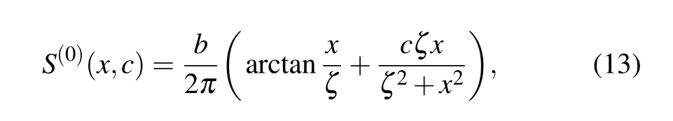
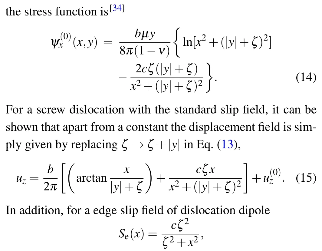

Obviously,for the slip fields given in superposition of the basic slipS(0),the related fields can be obtained by the superposition principle. Therefore,from Eqs.(14)–(16),using the superposition principle, the stress field and the displacement can be explicitly evaluated for each individual dislocation discussed above.[34,56,57]The analytical expressions of the stress fields are very complex and omitted here. In Figs.12–14,the stress fields are plotted for the 90◦dislocation, the 60◦dislocation and the screw dislocation respectively.

Fig.13. The stress field on the plane perpendicular to the 60◦dislocation line(z-axis). The stress is measured by the shear modulusµ and the length is measured by the lattice constant a. The x-axis is chosen to be parallel to the edge component of Burgers vector.

Fig.14. The stress field on the plane perpendicular to the screw dislocation line(z-axis). The stress is measured by the shear modulus µ and the length is measured by the lattice constant a. The slip field used is taken from Ref.[36].
7. The dislocation cores from the first principle calculations
As is well known, the long range feature of the dislocations makes it difficult to simulate the dislocation precisely.Usually, the periodic array of dislocation dipoles is used in dislocation simulations. However,when the long range problem is overcome for the array of dislocation dipoles, the interaction between the dislocation and anti-dislocation is introduced. The interaction between the dislocations falls off inversely proportional to the distance, and is not small for the small periodic cell.
It is efficient to simulate the dislocation core with help of analytical predictions because the dislocation core actually involves a few atoms around the center of the dislocation and the far field can be precisely obtained in the elastic theory. We suggest to simulate dislocation in the electron density functional theory using the shelled cell given by a pre-calculation carried out in the fully discrete Peierls theory. The shelled cell contains an isolated dislocation with a rigid shell in which the atom positions are given by the theory prediction. As long as the thickness of the shell is larger than the characteristic length of the interaction range,the surface effects are negligible and the relaxation will take place only at the core,and thus an accurate dislocation core can be obtained from the first principle simulation.

Fig.15. The atom alignments on the a-plane and b-plane of the edge dislocation given by the theory(big empty circles)and the first-principles calculation(small solid circles). There are 252 atoms in the super-cell used. The initial total energy is −902.215 eV and the final energy is −902.447 eV.Theoretical prediction is confirmed satisfactorily.
In order to confirm the theoretical predictions, the 90◦,60◦and screw dislocation cores are relaxed by using the Viennaab initiosimulation package (VASP) developed at the Institut fur Materialphysik of Universitat Wien.[58–60]The Perdew–Burke–Ernzernhof exchange-correlation functional for the generalized gradient-approximation is used in our calculations. A plane wave basis is employed within the framework of the projector augmented wave method.The structure is relaxed with a plane-wave energy cutoff of 450 eV. The iteration convergence is chosen to be 10−4eV and 10−3eV/˚A for the energy and the force respectively.

Fig.16. The atom alignments on the a-plane and b-plane of the 60◦dislocation given by the theory(big empty circles)and the first-principles calculation(small solid circles). There are 204 atoms in the super-cell used. The initial total energy is −725.666 eV and the final energy is−726.665 eV. The dotted and the solid lines are respectively used to label the partial dislocation centers obtained from the theory and the simulation. It seems that the core has a translation shift after relaxation.
In the first principle simulation, the supercell is constructed layer by layer. Firstly the nearest neighboring atom layer of the cut-plane,thea-layer(a-plane)and theb-layer(bplane) are obtained from the slip field or displacement field.Because the atom aligned periodically along the dislocation line,we take a period as the width of the layers. The layer size in direction perpendicular to the dislocation line is taken to be 20b ≈14a,which is much larger that the core size(∼5a).The layer next to thea-layer(orb-layer)can be obtained similarly and the other layers can be added one by one continuously.The total layer number is 6 in our supercell.The supercell constructed is a prism that contains an isolated dislocation. Out of the prism, there is a 10 ˚A thick vacuum layer. In our calculations, a fixed out shell is chosen suitably to eliminate the surface effects, and the interior atoms are fully relaxed. The final simulation results are shown in Figs. 15–17. It can be seen that the theoretical predictions are considerably well confirmed by the first principle simulation except that the core of the 60◦dislocation has a small shift after relaxation.
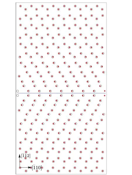
Fig. 17. The atom alignments on the a-plane and b-plane of the screw dislocation given by the theory(big empty circles)and the firstprinciples calculation(small solid circles). There are 108 atoms in the super-cell used. The initial total energy is −371.286 eV and the final energy is −371.479 eV.The energy drop is 0.193 eV in the relaxation process.
8. Conclusions
In summary, for temperature range 0≤T ≤900 K the core structure,the core energy and the Peierls stress are investigated for the 90◦dislocation and 60◦dislocations in Al using the fully discrete Peierls model. For the 90◦dislocation, the core clearly dissociates into two partial dislocations with the separating distanceD ∼12 ˚A, which is larger than that (3b)obtained in Ref. [29]. The characteristic width of the partial dislocations is about 8 ˚A for the edge component. As for the screw component,there are two characteristic lengthes: one is about 6.5 ˚A, and the other is about 9.5 ˚A. The Peierls stress is very smallσp<1 kPa due to the large characteristic width and the small step length of the 90◦dislocation.The 60◦dislocation dissociates into the 30◦and the 90◦partial dislocations with the separating distanceD ∼11 ˚A,and the Peierls stress is about several MPa. Due to the asymmetric feature of the 60◦dislocation,the core structure is more complex than that of the edge dislocation. The minimum characteristic length is about 5 ˚A and the maximum characteristic length is about 12 ˚A.The stress distribution is calculated by virtue of the superposition principle. The maximum stress on the misfit plane is as large as 0.1µfor all types of the dislocations. The core structures predicted theoretically atT=0 K are confirmed by numerical simulation based on the electron density functional theory.The satisfactory agreement between the theoretical predictions and the first principle simulations indicates that the results presented are accurate and reliable. For both the 90◦dislocation and 60◦dislocations, no stability transformation in the core structure is observed in the temperature range 0≤T ≤900 K while there is stability transformation atT ∼700 K for the screw dislocation.[36]The reason is unclear and needs to be explored further. From Table 1, one can see that the physics parameters in the energy functional change remarkably as temperature increases. However, because the changes of all parameters have the same tendency to become small and the equilibrium dislocation core mainly depends on the rescaled values of those parameters, the characteristic lengths of the dislocation cores given in Tables 2–5 change a little as temperature increases. Compared to the weak dependence of the core structure on temperature, the self energyEi(interaction energy of the infinitesimal dislocations)and the misfit energyEγfall off significantly as temperature increases. As shown in Fig.11, for all the three types of dislocations, the drops in self energyEiand the misfit energyEγare approximately as large as one third when temperature increases fromT=0 K toT=900 K.Therefore, as a sum of the self energy and the misfit energy, the dislocation energy at high temperature has an observable reduction compared with that at low temperature. In addition,it is notable that the Peierls stress of the 60◦dislocation grows up from 1 MPa to 2 MPa as the temperature increases from 0 K to 900 K.
Acknowledgement
Project supported by the National Natural Science Foundation of China(Grant Nos.11874093 and 11974062).
猜你喜欢
杂志排行

Chinese Physics B的其它文章
- Magnetic properties of oxides and silicon single crystals
- Non-universal Fermi polaron in quasi two-dimensional quantum gases
- Purification in entanglement distribution with deep quantum neural network
- New insight into the mechanism of DNA polymerase I revealed by single-molecule FRET studies of Klenow fragment
- A 4×4 metal-semiconductor-metal rectangular deep-ultraviolet detector array of Ga2O3 photoconductor with high photo response
- Wake-up effect in Hf0.4Zr0.6O2 ferroelectric thin-film capacitors under a cycling electric field