Damage characteristics of YAG transparent ceramics under different loading conditions
2022-08-30KuoBoXinfengZhngGuijiWngJijieDengToChongDnHnBingqingLuoMengtingTn
Kuo Bo ,Xin-feng Zhng ,* ,Gui-ji Wng ,Ji-jie Deng ,To Chong ,Dn Hn ,Bing-qing Luo ,Meng-ting Tn
a School of Mechanical Engineering,Nanjing University of Science & Technology,Nanjing,210094,China
b Institute of Fluid Physics,CAEP,Mianyang,621900,China
c Shanghai Institute of Ceramics,Chinese Academy of Sciences,Shanghai,200050,China
Keywords:YAG transparent Ceramics Damage characteristics Impact loading Shock compression Spall strength
ABSTRACT YAG (Y3Al5O12) transparent ceramics have attractive application prospects for transparent armor protection modules because of their excellent light transmittance and anti-ballistic capability.Understanding the fracture behavior and damage mechanism of YAG is necessary for armor design.To explore the damage characteristics of YAG under compression and tension,shock compression and shockless spalling experiments with soft recovery technique are conducted.The spall strength of YAG is obtained and the recovered samples are observed by CT and SEM.It is shown that the macroscopic damage characteristic of YAG under compression is vertical split cracks with oblique fine cracks distributed in the entire sample,while that under tension is horizontal transgranular cracks concentrated near the main spall surface.The cracks generated by macroscopic compression,tension and shear stress extend in similar tensile form at the microscale.The proportion of transgranular fractures on spall surfaces is higher than that of cracks induced by macroscopic compression.Meanwhile,higher loading rate and longer loading duration increase the transgranular fracture percentage.
1.Introduction
As transparent ceramics have a great advantage in light transmittance and anti-ballistic capabilities,the target using transparent ceramics as the strike-face layer has better ballistic performance than the traditional one made of bullet-proof glass in the same areal density.A preferential choice is to use transparent ceramics in the armor protection of equipment such as the armored helicopter,vehicle and missile fairings for light weight purpose.YAG(YAlO)is an oxide with a cubic structure formed by the reaction between YOand AlO.Compared with the properties of other transparent ceramics,the density of YAG is much higher,and the mechanism such as fracture toughness and hardness is slightly weaker.However,YAG has better light permeability,easier sintering process and lower manufacture cost [1,2],which shows the attractive prospect on engineering application.In addition,previous study has shown the good ballistic performance of YAG[3].These advantages make YAG a promising material for transparent armor.Armor design depends on the damage mechanism of ceramics under different loading conditions,such as compression,shearing and tension.The microscopic and macroscopic damage characteristics,directly reflecting the inelastic responses,are essential for exploring the damage mechanism.Generally,cracks with various distributions,densities and sizes is the main damage characteristic at the macroscale.In comparison,microscale(generally grain size scale)distinctly reflects the inhomogeneity of ceramics.Intergranular and transgranular fracture modes represent two different energy consumption levels.The propagation paths of cracks are determined by the competition between the two failure modes.The macroscopic mechanical properties of ceramics are also strongly affected by damage evolution.
The resistance to tension of ceramics is much weaker than that to compression.The failure characteristics of ceramics under the two loading conditions are significantly different.Louro [4] found the orthogonal distribution mode of macroscopic cracks under compression in plate impact experiments of AlOThe tension in spalling experiments generated randomly distributed cracks.Both intergranular and transgranular fracture modes were observed under two loading conditions,and the fracture mode in regions far from the main spall surface was mainly intergranular fracture.Longy [5] inferred that the tensile fracture was induced by cracks,voids and the glass phase.He also concluded that the stress release in regions near the spall surfaces lessened crack generation.However,few studies paid attention to the comparable damage characteristics of transparent ceramics under compression and tension.
Historically,the peak stress value and loading rate significantly affect crack distribution and propagation.In general,the density and number of macroscopic fragments increase with the macroscopic strain rate [6],which corresponds to a large amount of energy consumption of ceramics.According to the observation in the spalling experiments of alumina ceramics performed by Louro[4],the main spall surface gradually moved towards the loading surface and the size of macroscopic fragments became uniform with the increase of compression loading duration.Meanwhile,a large number of experiments manifested that the cracks tend to be intergranular at low loading rate and transgranular at high loading rate at the microscale.For example,the fracture mode of AlO[7-10] ceramics gradually changes from intergranular to transgranular fracture as the loading stress changes from below HEL to above HEL.Cracks of spinel,AlON and other ceramics also show the transition from intergranular fracture to transgranular fracture as the loading rate increases[11-13].Subhash[14]suggested that the intergranular propagation of cracks occurred preferentially at low loading rates.Landkord [15] believed that the slip was difficult to occur with the increase of strain rate and in turn hindered microplasticity or crack propagation,leading to the increase of ceramic strength.However,Shih[16]observed transgranular fracture of SiC under both quasi-static and dynamic loadings and drew a conclusion that the fracture mode is rate-independent.Strassburg [13]found the main fracture mode of spinel in penetration experiments using complex loadings is intergranular fracture.The strain rate effect of ceramic materials in microscale failure is particularly prominent.In previous studies,the transgranular fracture of YAG was observed under quasi-static and dynamic loadings[17,18].The crack length in indentation experiments increases with the decrease of loading rate and increase of loads [18].Nevertheless,insufficient works have focused on the strain rate effect on the fracture surface characteristics of YAG.The relationship between loading conditions and microscopic responses of YAG remain unclear.A detailed observation is needed to study the damage mechanism,so as to provide the basis for the optimization of material preparation technologies.
Penetration and fragment impact experiments feature complex stress distributions and loading histories,while the macroscopic stress of samples in one-dimensional loading experiments such as the plate impact experiment show singleness and controllability,which provides an important way for studying the damage characteristics of materials under specific loading conditions.The shock compression experiment provides a simple shock compression wave high loading rates.The shockless spalling experiment provides a ramp compression wave at relative lower loading rates and with a follower tension loading.The differences of two loading methods can help explore the effect of loading form and loading rate to damage characteristics of YAG.In this work,shock compression and shockless spalling experiments using the softrecovery technique are performed to explore the fracture mechanism of YAG transparent ceramics.The recovered samples are observed at the macroscale and microscale levels and the relationship between fracture mechanisms and loading responses are analyzed.
2.Experimental techniques and loading conditions
2.1.Material characteristics
YAG ceramics used in the experiments were sintered by dry pressing process and provided by Shanghai Institute of Ceramics.The material parameters of typical characteristics of YAG ceramics were tested as listed in Table 1.

Table 1.Material parameters of YAG transparent ceramic.
2.2.Experimental facility
The loading experiments were carried out on the CQ-4 electromagnetic loading platform developed by the Institute of Fluid Fhysics,China Academy of Engineering Physics(CAEP).Ramp wave loading and shock loading experiments can be performed on this platform to study the dynamic responses of materials under high pressures and strain rates [19].The frequency signal measured by DLHV (Dual Laser Heterodyne Velocimetry) is processed by spectrum conversion and filtering to obtain the particle velocity [20].The error of experimental data is within 1%.Details of the CQ-4 electromagnetic loading platform are given in literature [19-21].
2.3.Experimental principle of shockless spalling
The principle of shockless spalling using soft-recovery technique is shown in Fig.1.The strong current derived from the device propagate along the inner-surface of cathode and anode panels in a short circuit.The Lorenz force is generated under the interaction of the magnetic field and current.The electromagnetic compressive pulse propagates in the form of plane waves along the panel thickness.The samples are bounded on panels by epoxy resin,controlled at 2-3 μm in thickness.The whole loading and unloading waveform is similar to the half period of the sine curve.The samples are first loaded by raising compression pulse,so the shockless process is regarded as quasi-isentropic loading.Then the unloading wave intersects with the rarefaction wave reflected from the rear surface of the samples,which gradually turns the stress in the sample from compression to tension.Spalling occurs inside the samples after the tensile stress reaches the threshold.
Since the loading history generated from two side of panels is the same,the same loading history of the samples on the two sides can be guaranteed when the whole panel-sample structure is designed to be symmetric.Therefore,by setting one side of the panels for recording and the other side for recovery,the dynamic response history of the recovered samples can be obtained.For the soft-recovery side,the panel is designed as a groove to confine the sample.The slotting is processed to form a weak connection zone beside the confinement part of the panel.With the increase of compressive stress,the entire confinement part is cut from the panel homogeneously along the slot and then flies into the softrecovery cavity filled with rubber and poly foam.An aluminum cover plate is bounded behind the sample,together with the confinement,to maintain the integrity of the loaded sample.The panels are made of Oxygen-free Conductivity Copper (OFHC).Consequently,the lateral rarefaction wave from the sample-panelinterface is reduced since the shock impedance of the panel is similar to that of YAG.
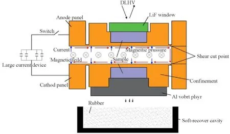
Fig.1.Experimental principle of shockless spalling using soft-recovery technique on the CQ-4 electromagnetic loading platform.
The panel of the recording side is the same as that of the recovery side.A window made by LiF(ρ:2638 kg/m,C:5150 m/s,refractive index:1.28)is bounded behind the sample to obtain the stable interface particle velocity.The minimum difference of shock impedance of LiF with that of aluminum guarantee the same loading history of the sample on the two sides of the panel.The rear surface of the sample is coated with a thin aluminum film (about 0.5 μm in thickness) to reflect signal frequency.A pin of DLHV is placed above the center of the sample surface to record signals.
Two shots are fired to verify the reliability of the measured results,and one is used for soft recovery.Considering the loading capacity,the sample size and panel thickness are set to be φ20 × 6 mm and 2 mm,respectively.The loading duration is controlled at about 600 ns.The experimental conditions are shown in Table 2.
2.4.Experimental principle of shock compression
The principle of YAG shock compression soft-recovery experiments is shown in Fig.2.One side of the panel is designed to record the flyer plate velocity and the other to recover the sample.Similar to the panel in the spalling experiment,the slot is processed at the root of the panel to form the flyer plate [19,22-25].For the softrecovery side,the sample is inlayed in OFHC confinement.The flyer first impacts the OFHC,leading to good homogeneity of shock waves.The confinement can prevent the generation of rarefaction waves from the lateral or rear surface.Meanwhile,the sample is recovered more completely than in the direct impact condition.A moment trap made of OFHC with the size of φ42 × 300 mm is set behind the confinement to absorb energy.For the recording side,the flyer plate velocity is measured by the pin of DLHV.The sample size is set as φ40 × 8 mm,and the substrate is 3 mm in thickness.The loading conditions are shown in Table 2.

Table 2.Experimental conditions of shock compression and shockless spalling.
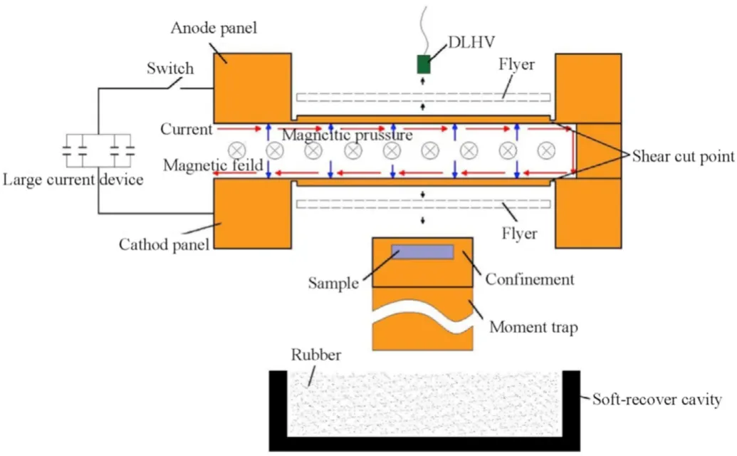
Fig.2.Experimental principle of shock compression using soft-recovery technique on the CQ-4 electromagnetic loading platform.
2.5.Measured results and spall strength
The sample-window interface velocities under shockless spalling are shown in Fig.3.The repeatability of the experimental data demonstrates the reliability of the measured results.The samples undergo ramp compression with a rise time of about 0.6 μs,which is then unloaded.The spalling is generated in the samples as the interface velocity changes from Uto Uat about 0.9 μs.Then the particle velocity jumps back by the reflected compression wave.
The true interface particle velocities Uand in-situ particle velocity Uare converted from the measured interface particle velocity Uby the approximation method in Eq.(1)[26].The peak stress is 2.3 GPa obtained by Eq.(2)~(3) and the spall strength is 548 MPa from Eq.(4).

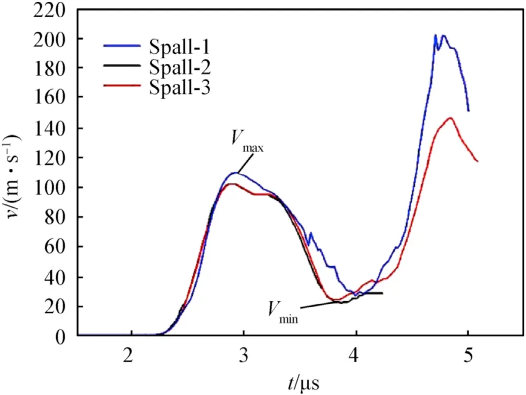
Fig.3.Sample-window interface velocities in shockless spalling experiments.

where β is the refractive index of the LiF window,zis the impact impedance of LiF,zis the impact impedance of YAG,Uand Uare the maximal and minimal true interface particle velocities,respectively,C=5150+2.7Uis the sound speed of the LiF window,and C=8626+4Uis the sound speed of YAG.
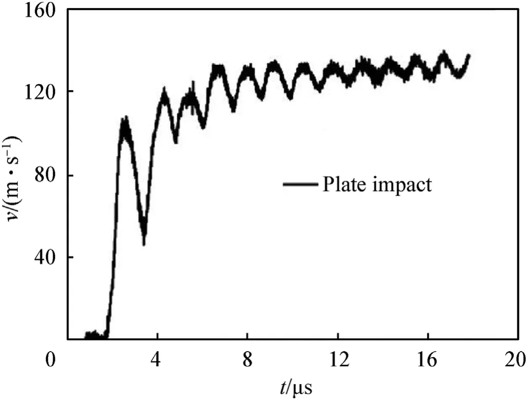
Fig.4.Impact velocities of the flyer plate in plate impact experiments.
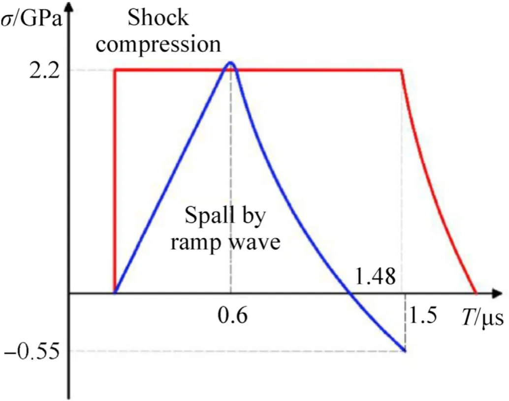
Fig.5.Comparison of loading conditions between shock compression and shockless spalling.
The impact velocity of the flyer plate is shown in Fig.4.The final impact velocity is about 130 m/s and the shock stress of the sample is 2.2 GPa by the impedance matching method.The duration of shock compression is 1.48 μs calculated from the thickness and shock wave speed of the flyer plate.The peak stresses of shock compression (peak stress of 2.2 GPa) and shockless spalling (peak stress of 2.3 GPa) experiments are similar.According to the rise time and peak longitudinal stress,the compressive loading rate of samples under shockless spalling is 3.7×10Pa/s.The rise time of samples under shock compression is 0.28 μs from finite element simulation.The compressive loading rate of samples is determined as 8.2 × 10Pa/s,which is much higher than under shockless spalling.The main differences of the two loading conditions are as follows:1.The loading rate of samples under shock compression is much higher than under spalling.2.The duration of compression in shock experiments is twice of that in spalling experiments and the input energy of shock compression is higher,as illustrated in Fig.5.
3.Macroscopic damage characteristics of YAG ceramics
The samples with a high degree of integrity are recovered in the two types of experiments.The macroscopic damage characteristics of YAG ceramics are observed by CT scanning and sectioning of samples.
3.1.Macroscopic damage of samples under shock compression
The figures of soft-recovered samples under shock compression by CT scanning along the axis direction are shown in Fig.6.The net of large cracks near the impact surface are obvious.The large vertical cracks extend straightforward from the impact surface and the distribution of the crack net almost keeps constant.The sample can be regarded as only experiencing the compression stage since the rarefaction waves are fully absorbed by the moment trap.Therefore,these vertical split cracks are caused by shock compression.CT scaning along the cross-section direction in Fig.7(b) shows large cracks extending to the rear surface.Meanwhile,some cracks are arrested in midway,leading to less cracks near the rear surface than the loading surface.
The cross-section of the recovered sample is shown in Fig.7(a).Shock compression generates a large amount of oblique orthogonal cracks.Most oblique cracks have an angle of 45to the impact surface and divide the sample into rhombic regions.The absence of oblique cracks in CT scaning manifests that the width of cracks is much smaller than that of vertical split cracks.The macroscopic damage mode of YAG under shock compression in the present work is similar to that of alumina ceramics in the experiment by Louro[4].
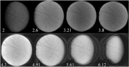
Fig.6.CT scaning along axis direction of soft-recovered samples under shock compression.
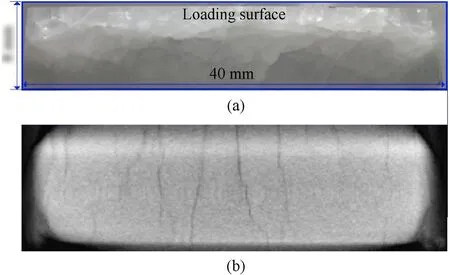
Fig.7.Cross-section (a) and CT scaning along cross-section direction (b) of softrecovered samples under shock compression.
3.2.Macroscopic damage of sample under shockless spalling
Results of CT scaning along the axis direction of the samples under shockless spalling are shown in Fig.8.The numbers at the left bottom of the figure represent the distance from the loading surface.The breakage at the edge of the loading surface caused by sampling does not affect the observation of the rest part.The dark region at the centre of the sample in Fig.8 represents fine cracks.The density of fine cracks shows a gradual change from the impact surface to the rear surface.The density at the middle of the sample along the axis direction is higher than that on the loading and rear surfaces.The surface with the densest fine cracks is the spall surface about 3.2 mm away from the loading surface,which can also be distinctly observed at the same location in the figure of crosssection (Fig.9(a)) and the figure of CT scanning along the crosssection direction (Fig.9(b)).Meanwhile,a large number of secondary tensile cracks concentrated near the main spall surface can be observed in Fig.9(a).
Vertical cracks generated by compression stress under ramp wave loading perpendicular to the spall surface are observed in Fig.9(a).The sample is divided by the vertical and horizontal cracks into an orthogonal net.These vertical cracks are distinct and wide in the part of the samples from the spall surface to the rear surface(i.e.the spall segment) and are sparse in the part of the samples from the loading surface to the spall surface.The vertical crack density difference of the two part of the samples may be formed by the secondary compression waves generated by the reflection of rarefaction waves in the spall segment.The macroscopic damage characteristics of YAG are similar to those of AlOand SiC under shockless spalling [27,28] and shock spalling by Louro [4],respectively.
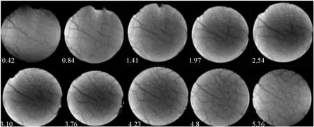
Fig.8.CT scanning along axis direction of recovered samples under spalling by ramp wave loading experiments.
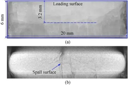
Fig.9.Cross-section (a) and CT scaning along cross-section direction (b) of recovered samples under shockless spalling.
3.3.Microscopic fracture of samples under quasi-static compression loading
The microscopic damage characteristics of samples are observed by SEM to study the fracture mechanism.Microscopic fractures after quasi-static compression are initially observed for comparation to explore the effect of loading rates on microscopic damage.The fracture surfaces of the segments of samples with an average grain size of 10 μm under quasi-static compression are shown in Fig.10.The fracture characteristics of different fragments or different sections of the same fragment show great difference due to microstructure heterogeneity and microscopic stress field[29].For example,the fracture surface in Fig.10(b) is mainly transgranular while that in Fig.10(c)is mainly intergranular with a strong grain sense.The regions only contain intergranular or transgranular fractures are observed shown in Fig.11(a) and Fig.11(c)-(d),respectively.Some mixed regions are consisted of alternate intergranular or transgranular regions as shown in Fig.11(b).In the transgranular region,there are unrecognizable and smooth cleavage fracture surfaces,showing weak transgranular extension,shown in Fig.11(c).Besides,some regions show intense transgranular fracture in Fig.11(d).The numerous cleavage cracks,in the form of C-shaped curved lines in intense tansgranular regions represent the Wallner lines.These continuous cleavage steps manifest the weak influence of grain boundaries on crack extension.The red circle in Fig.11(b)also exhibits the same directions of cleavage steps generated by cracks crossing the small-angle twist grain boundary.It seems that the thin grain boundary of YAG enhances the tendency of crack propagation in the original direction without the influence of the crystal direction.
The double slip bands in blue circles in Fig.12 and the slip bands from grain boundaries in Fig.13 are observed.These plastic deformation features induced by dislocation generally occurs in the transgranular region.However,these obvious plastic deformation features are minor by observation in the recovered samples in all the experiments in the present paper.
3.4.Microscopic fracture of samples under shockless spalling
The recovered samples under shockless spalling were previously immersed in epoxy resin for fixing.Then samples were cut along the cross-section and sampled.The inward surfaces of the recovered samples were selected to prevent tool scratch during sampling.Typical vertical and horizontal cracks generated by compression and tension were observed (Fig.14).
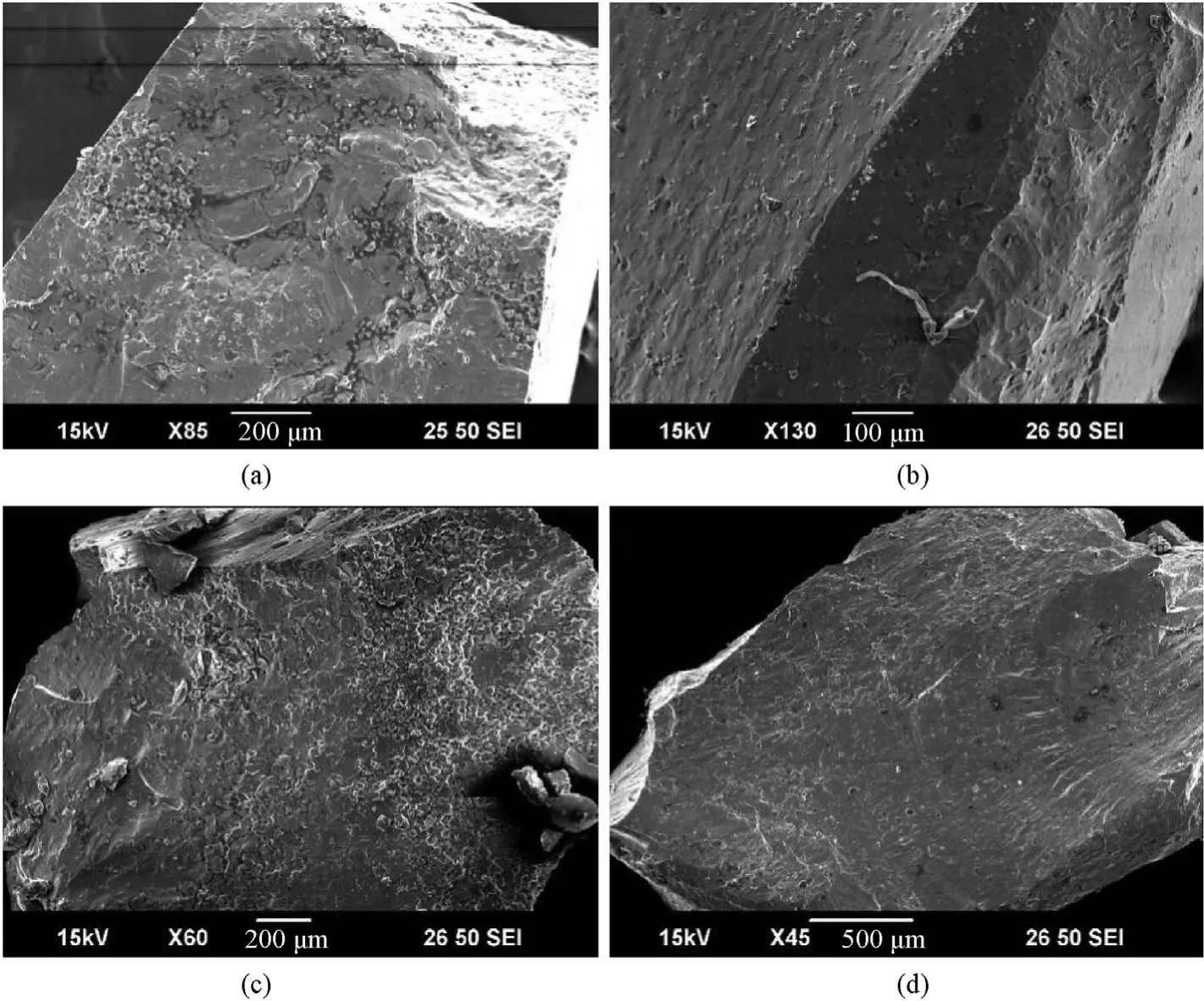
Fig.10.Significant difference between different fracture surfaces of fragments.
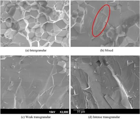
Fig.11.Three typical fracture regions under quasi-static compression of samples with a grain size of 10 μm.
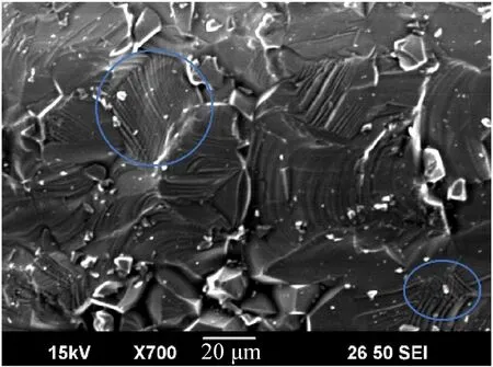
Fig.12.Dispersed directions of cleavage steps and double slip bands.
The main fracture mode of vertical cracks is intergranular fracture as shown in Fig.15(a),while that of horizontal cracks is intense transgranular fracture as presented in Fig.16 and Fig.17.According to the size of the area where the grains under different fracture mode are located,the intergranular fracture ratio are obtained as shown in Fig.15(b).The blue and red regions represent the transgranular and intergranular regions,respectively.The intergranular ratio of Fig.15(a) is 43%.The intergranular fracture ratios of vertical and horizontal cracks are about 42% and 18%,respectively,determined by averaging the intergranular fracture value of several figures.A large number of alternate dark and light regions which do not appear during quasi-static compression occur in both horizontal and vertical cracks.These regions represent the layering and the multilayer stack.The smooth arc-shaped edges of these layered regions demonstrate the transgranular fracture mode.The size of the layered area varies from the isolated island across several grains to the connecting area across dozens of grains.The area of the single circular arc-layered region is smaller on the spall surface than that on the other surfaces.The dark layered area is about a half of the total,which is determined by averaging the proportion value of dark region of several figures.Meanwhile,the elliptical holes or circular holes appear on the surface of grains in the middle of some layered areas in Fig.17.The main fracture mode of surfaces with these holes is intense transgranular fracture.It is speculated that the layered regions are generated by the overlapping of parallel cracks.The influence of stress wave systems during crack propagation causes the arc-shaped edges.
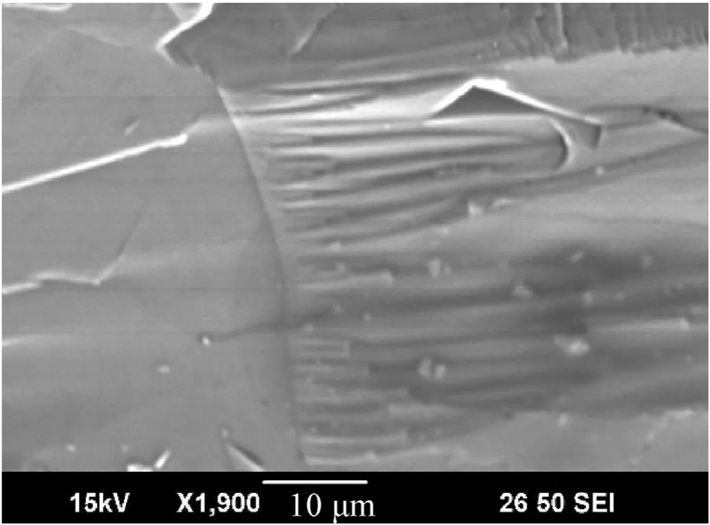
Fig.13.Slip bands from the grain boundary.
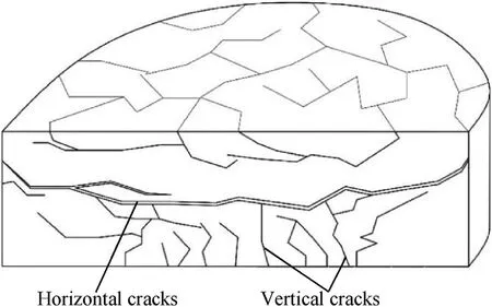
Fig.14.Sketch of vertical and horizontal cracks of the sample under shockless spalling.
3.5.Observation of microscopic fracture characteristics of samples under shock compression
The sampling method for samples under shock compression is the same as mentioned above.Typical vertical cracks of the sample under shock compression are shown in Fig.18.The average intergranular ratio of vertical cracks under shock compression is determined as 35%.The main fracture mode of vertical cracks of samples under shock compression is weak transgranular fracture.A large number of fragments and crushing fractures of grains in the transgranular region indicate the intensive extruding of grains as shown in Fig.19.Meanwhile,the fracture surface is significantly uneven.Fig.18(a) shows a large number of fluctuating fracture surfaces with a small area.The cracks perpendicular to fracture surfaces are also observed.These multidirectional fracture surfaces represent the fine zigzag propagation paths of cracks.Uneven fracture surfaces are also found in cracks under shockless spalling while the quantity is far less than under shock compression.Furthermore,the white arrows in Figs.17 and 20 show a few micropores with a diameter of about 1 μm generally distributing at the triple grain boundary in both loading ways.The micropores are likely to promote the formation of fracture surface under high strain rate loading.The layered surfaces are also found on the fracture surfaces of the sample under shock compression (Fig.21).The dark layered area is about a half of the total,which is almost the same with the fracture surface of sample under shockless spalling.It is found in Fig.22 that the transgranular cracks can be derived from the intergranular region.The regions B and C are originally combined and the observed surface is formed preferentially.The crack at point C bifurcates into two cracks perpendicular to the observed surface,which divides the cracks into B,C and D regions after the generation of a large number of intergranular cracks in region A.The cracks at a and b showed the main intergranular fracture mode.The fine oblique cracks generated by microscopic shear stress are shown in Fig.23.The transgranular crack proportions are various.For example,Fig.23(a) shows more intergranular fractures while Fig.23(b) shows more transgranular fractures.
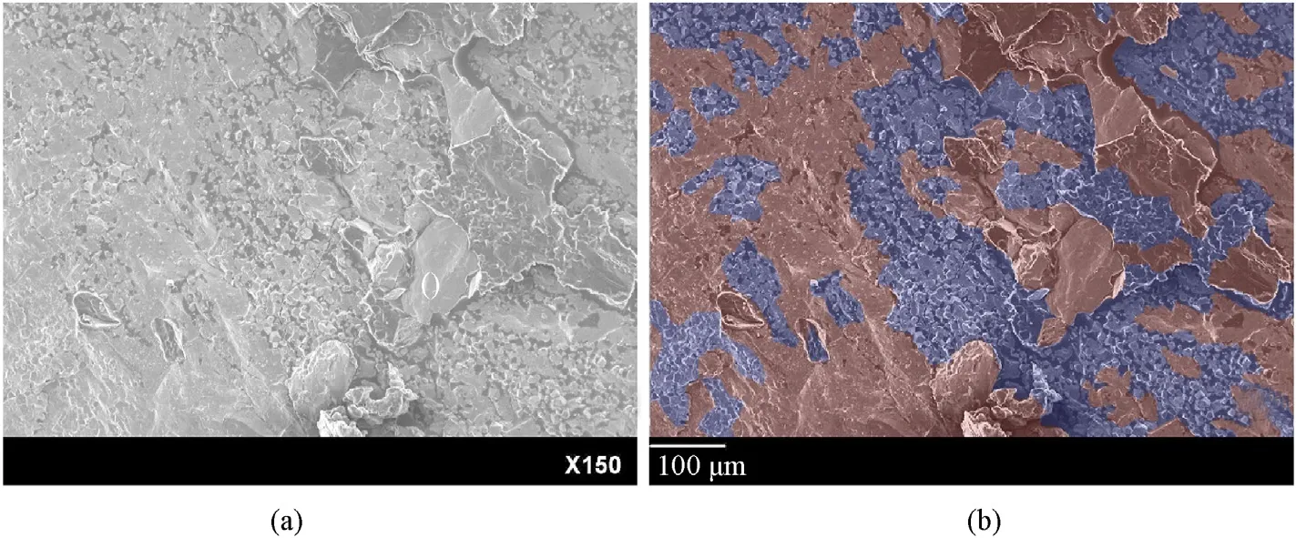
Fig.15.Origin and sub-regional figures of vertical cracks of the sample under shockless spalling.
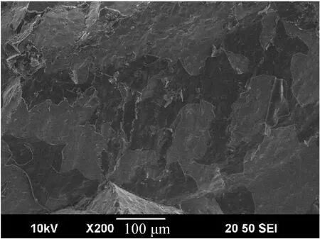
Fig.16.Horizontal cracks of the sample under shockless spalling.
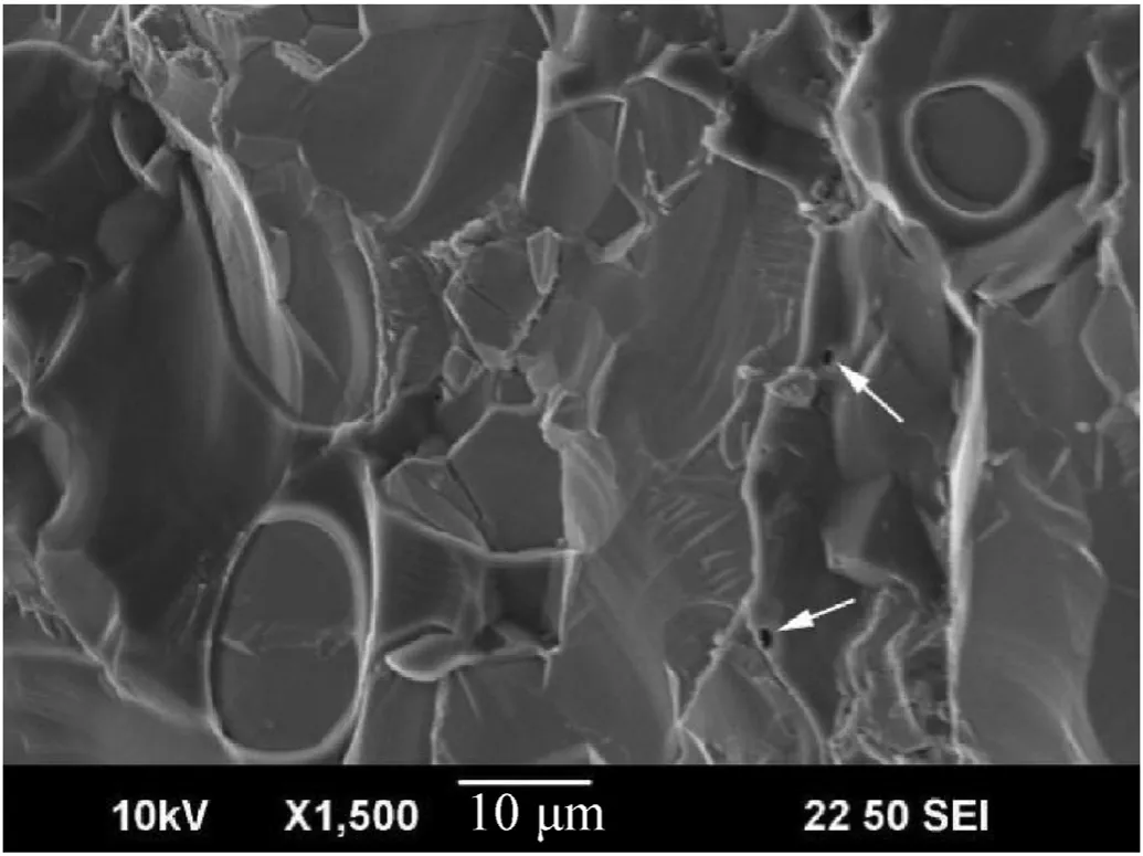
Fig.17.Circular holes in horizontal cracks of the sample under shockless spalling.
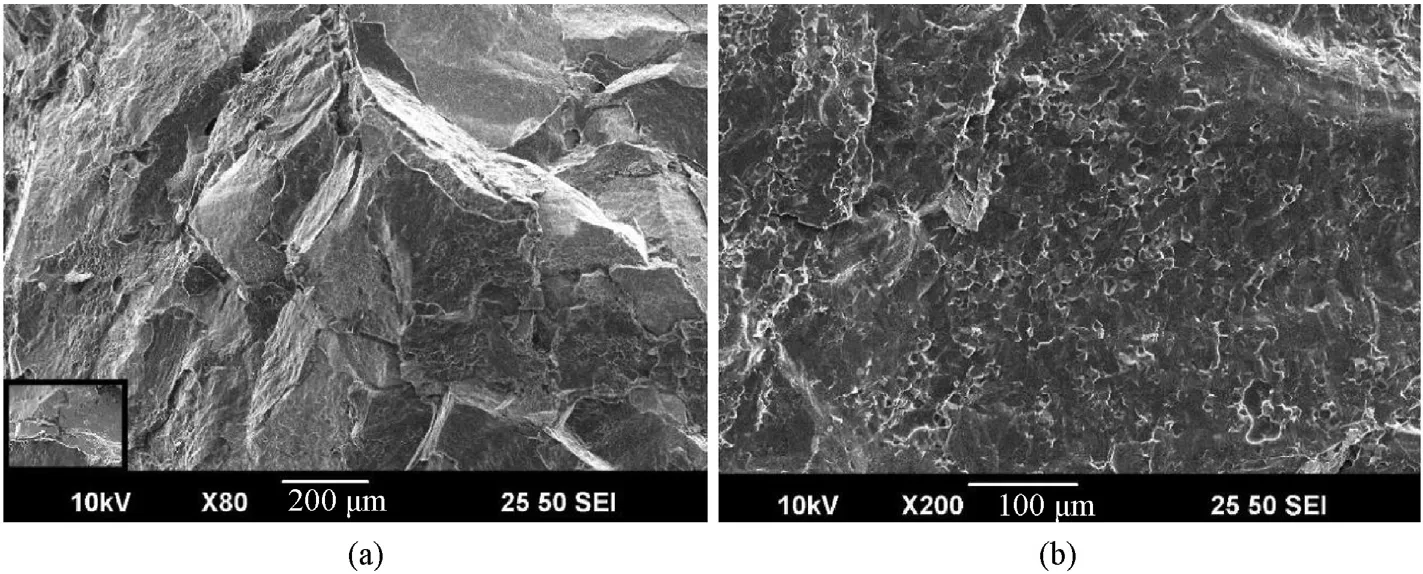
Fig.18.Vertical cracks of samples under shock compression.
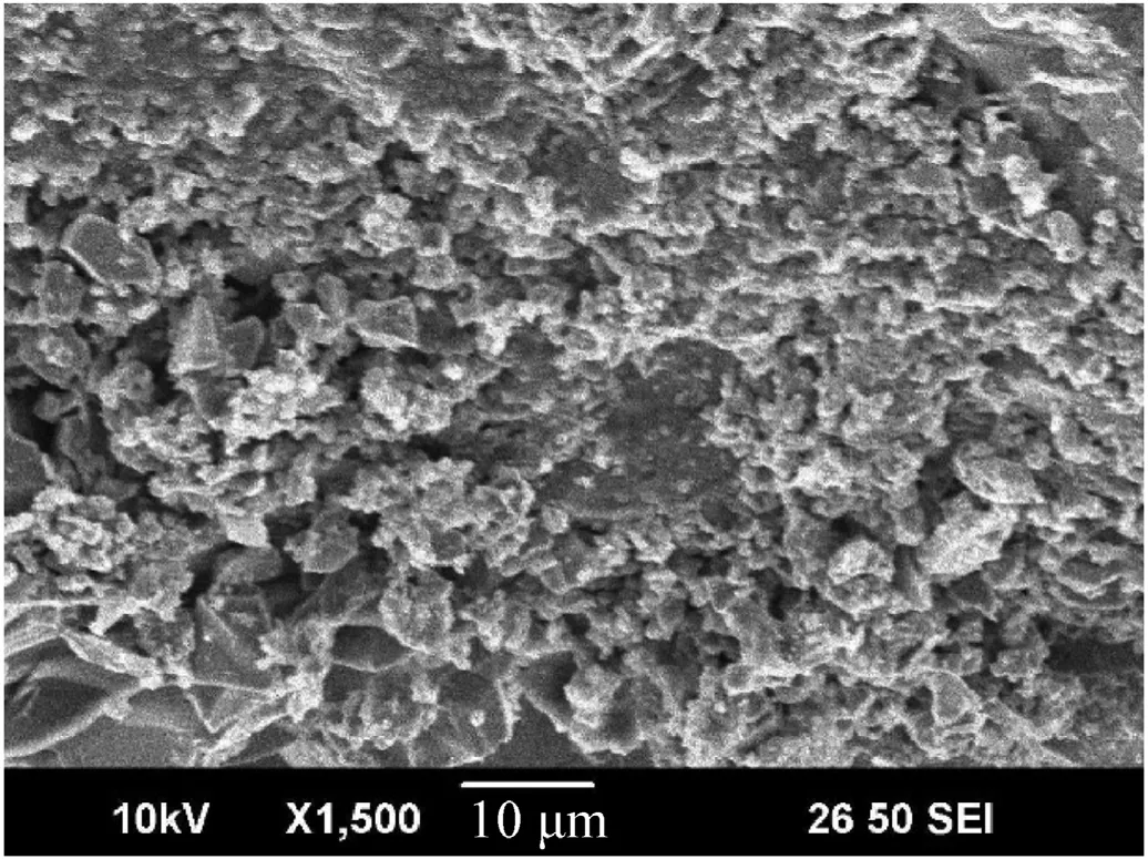
Fig.19.Grain crashing of the sample under shock compression.
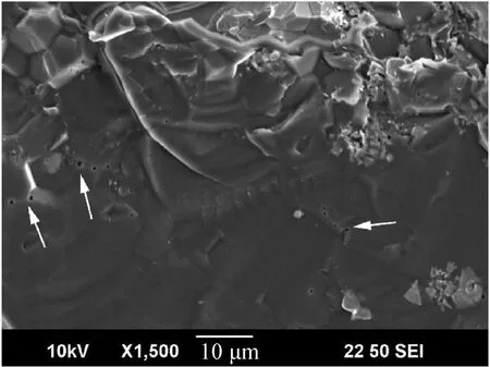
Fig.20.Porosity at grain boundaries.
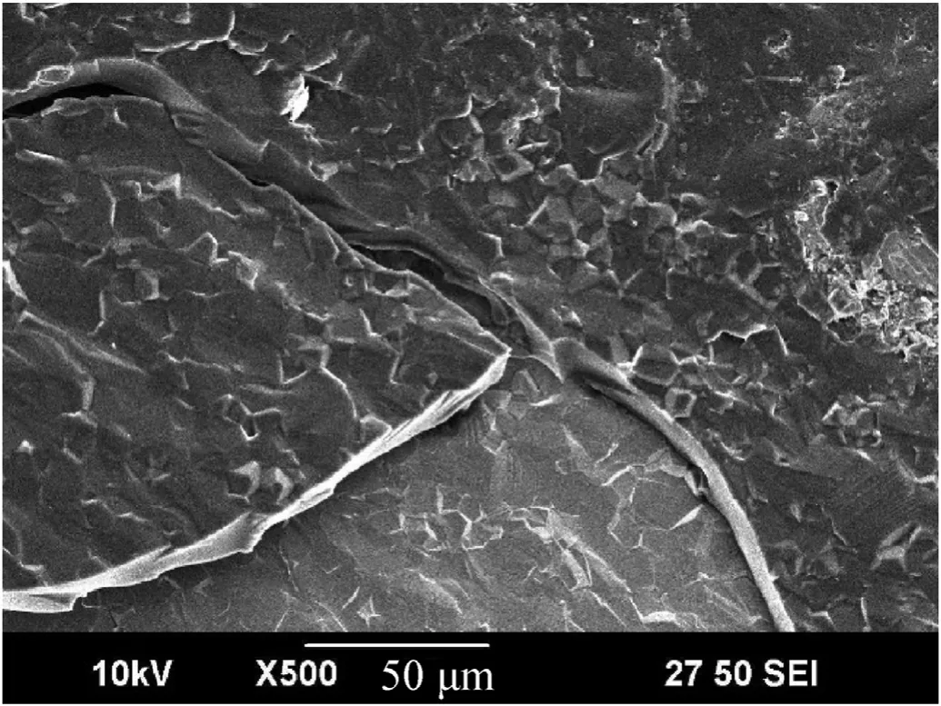
Fig.21.Layered cracks of the sample under shock compression.
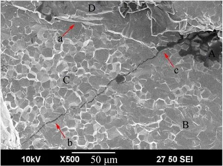
Fig.22.Derived transgranular cracks from the intergranular region of the sample under shock compression.
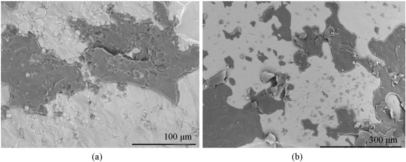
Fig.23.Microscopic features of fine oblique cracks under shock compression.
4.Discussions
The effect of loading rate on microscale fracture is discussed.The relationship and distinction between fracture characteristics under compression and tension are analyzed based on the observed fracture characteristics.
4.1.Effect of loading rate
According to the comparison of microscopic fracture characteristics of samples with a grain size of 10 μm in length under different loading conditions,it is manifested that the proportion of intergranular fractures of vertical cracks under shock compression(35%) is lower than under shockless spalling (42%),and the strain rate of the former is higher.It can be inferred that the transgranular fracture ratio of YAG is sensitive to loading rate.The increase of the loading rate significantly enhances the propagation capability of cracks.A large number of dislocations accumulate at grain boundaries within a short time under high loading rates leading to the stress concentration.The trend of transgranular fractures extending along the original direction prevails over that of intergranular fractures extending along the other directions.Nevertheless,the dislocation has relatively sufficient time to be transferred to the next grain under low loading rates.Therefore,the cracks choose the grain boundary path that is much conducive to extension and only produces transgranular factures if the local stress concentration is intense.
4.2.Effect of tension and compressive loads on damage
The macroscopic fracture of YAG under tensile and compressive loading are significantly different.Vertical cracks are formed in both shock compression and ramp wave compression stages while fine oblique cracks only appear under shock compression.It is shown that fine oblique cracks are generated due to long loading duration and high loading rates.From the aspect of energy consumption,cracks generated by compression are more conducive to energy absorption.The material still retains certain stiffness after the generation of large cracks due to the confinement of lateral displacement under one-dimensional strain compression.Therefore,the continuous compression leads to oblique fine cracks.The large-sized segments are further crushed and the fragments also abrade with each other.These progresses convert the energy of external loads into the surface energy and dislocation energy inside the ceramics,leading to sufficient energy absorption before being totally damaged.From the aspect of tension,the typical damage characteristic of YAG under tensile loading is the main spall surface with adjacent tensile cracks.More transgranular cracks on the spall surface than compression-induced cracks indicates that single tensile cracks can absorb more energy.Nevertheless,the spall surface interdicts the propagation of tension waves.The energy of external loads cannot be consumed by producing more cracks.The capacity of energy consumption of tensile cracks with finite density and scale is lower than that of compressive cracks.The reduction of rigidity of ceramic layers resulted from tensile fractures weakens the effect of further erosion on the projectile.Therefore,many methods for improving the ballistic performance of ceramics are actually realized by reducing tension,such as the methods of adding lateral confinement or prestress to prevent the extension of microcracks by tension,and employing the impedance matching back plate to reduce the amplitude of reflected tension waves.
Vertical split cracks,oblique fine cracks and spall cracks are formed by compression,shear and tension stress at the macroscale,respectively.Spall cracks can be regarded as being formed only by local microscale tension.However,the fracture surfaces of cracks under compression and shear stress are not significantly different with those under tension at the microscale except for the proportion of transgranular cracks.This similarity manifests that the microcrack propagation mechanisms of the three macroscopic loadings are the same at the microscale.A large number of cleavage cracks observed in fracture surfaces also indicates that the cracks are driven by tension normal to crack surfaces.When there is no confining pressure or the lateral stress is tension,the microcrack extends in tension mode.When the lateral stress is compression,the crack closes and generates plastic motion [30,31].Because of the heterogeneity of the microscopic stress field formed by microcrack extension,the local loads change from uniform onedimensional compression to the mixture of compressive,tensile and shear stresses.The low threshold for generatingIandII fracture modes(especially the I fracture mode)of most cracks promote the generation of local tension-induced cracks.Meanwhile,the release of lateral stress during crack propagation intensifies the trend of interconnection of cracks and destructive fracture.Therefore,the microscopic failure modes of surfaces induced by each kind of macroscopic loads are all tension fracture.
5.Summary and conclusions
Shock compression and shockless spalling experiments using soft-recovery technique of YAG transparent ceramics were performed in present study.The spall strength and recovered samples were obtained.According to the observation of damage characteristics at the microscale and macroscale levels,the relationship between loading conditions and dynamic response were analyzed.The main conclusions are as follows:
(1) The intergranular fracture proportion at the microscale of YAG under compression raise from 35% to 42% as the loading rate increases from 3.7 × 10Pa/s to 8.2 × 10Pa/s.The increase of loading rate and loading duration in the range of 0.28 μs-0.6 μs generate the fine oblique cracks at the macroscale.
(2) Macroscopic tension generates transgranular cracks.The total energy consumption of macroscopic tension-induced cracks is weaker than that of cracks induced by compression.
(3) The layered surface with smooth arc-shaped edges appears under both shock compression and shockless spalling.
The present study manifests that the impact-loading response of YAG transparent ceramics has certain particularity.Nevertheless,a considerable part of the fracture mechanism of YAG is similar to that of traditional non-transparent ceramic materials.The fundamental data in this work are conducive to establishing theoretical models or numerical simulation methods for YAG transparent ceramics.
The authors declare that they have no known competing financial interests or personal relationships that could have appeared to influence the work reported in this paper.
This work is funded by the National Natural Science Foundation of China (No.11772159),the NSAF Joint Fund (No.U1730101) and the Fundamental Research Funds for the Central Universities(No.30917011104).
杂志排行
Defence Technology的其它文章
- Experimental study on propagation characteristics of rotating detonation wave with kerosene fuel-rich gas
- Adaptive robust control for triple avoidance -striking -arrival performance of uncertain tank mechanical systems
- Experimental study on WFeNiMo high-entropy alloy projectile penetrating semi-infinite steel target
- Numerical investigation of a muzzle multiphase flow field using two underwater launch methods
- Shock wave and bubble characteristics of underwater array explosion of charges
- A micro-chip exploding foil initiator based on printed circuit board technology
