Numerical simulation study of sympathetic detonation in stages
2022-08-30TonghuiYangChengWangTaoLi
Tong-hui Yang,Cheng Wang,Tao Li
State Key Laboratory of Explosion Science and Technology,Beijing Institute of Technology,Beijing,100081,China
Keywords:Sympathetic detonation Explosives Numerical simulation
ABSTRACT A Direct Numerical Simulation (DNS) scheme for solving the temporal-spatial multiscale problem of sympathetic detonation is proposed.According to the physical and chemical properties,the SD process is divided into two stages in the numerical simulation.Two different grid sizes are used in the two stages to improve calculation accuracy and efficiency.The local Level Set Method is used to accurately track the multi-material interface,and the Harten Lax and van Leer Contact (HLLC) method is used to solve local Riemann problem.Based on the computing method mentioned above,choosing the high evolution Weighted Essentially Non-Oscillatory (WENO) scheme for the spatial discretization of governing equations in alliance with Total Variation Diminishing(TVD)Runge-Kutta for time discretization,the Eulerian code of SD is developed.It solves the data interaction between the two solvers with variable grid size and time step,and realizes the three-dimensional parallel computing of SD.Composition B is taken as the research object.The processes of SD in different stand-off distances are analyzed.The transmission and safety distances of Composition B are given.The test under the same conditions is designed to verify the numerical simulation.The numerical simulation results are in good agreement with the experiment,which proves the accuracy and feasibility of the numerical method.
1.Introduction
Sympathetic detonation (SD) is a detonation of an explosive charge by a nearby explosion.It needs to be considered in the safety design of explosive use,storage,transportation and production.Experiments are the most common method to study the characteristics of SD.Ishikawa et al.[1] determined the relationship between the gap thickness and amount of explosives by the sand gap test.Chen et al.[2]established a model of the expansion progress of shell expanding and the randomly forming process of fragments,and conducted sympathetic reaction test of GHL explosive charges with shell.Zhang et al.[3]conducted a set of underwater sympathetic detonation tests,and analyzed the energy,pressure,and bubble pulsing cycle.Cheng et al.[4]carried out underwater explosion experiments and studied the impact of RDX booster on emulsion explosives between different distance.Obtained the law of overpressure in the near field underwater.Xiao et al.[5]developed a numerical simulation method to predict the sympathetic detonation behavior of fuze explosive trains under the impact of blast fragments.LS-DYNA3D was used to carry out the numerical simulation of the sympathetic detonation of the cased charges,and it was verified with the experiment.Yang et al.[6]investigated the low vulnerability of the FOX-7/RDX-based aluminized explosives formulation by sympathetic detonation tests.In recent years,numerical simulation has received widespread attention as an efficient research method.Kubota et al.[7]carried out numerical simulations of SD in the gap test by a Cubic interpolated pseudoparticle method (CIP)Eulerian code,and found a linear relationship between the critical gap length and the charge weight.Kim et al.[8]proposed a numerical simulation scheme to investigate the SD of a cylindrical explosive charge contained in a steel casing,which can replace related experiments to a certain extent.Ma et al.[9]calibrated reactive burn model SURF and successfully used it to simulate sympathetic initiation.
The high-order WENO finite difference method has high accuracy and stability for solving strong discontinuity problems,and is suitable for high-precision simulation of explosive initiation and explosion process [10-14].However,the temporal-spatial multiscale problem increases the complexity of the numerical simulation of the Sympathetic detonation (SD) process.Existing simulation schemes cannot give a good balance between accuracy and efficiency.The propagation process of detonation is generally on the meter or sub-meter scale,while the chemical reaction in the explosives occurs on the millimeter scale.In order to describe the chemical reaction zone in the explosives,it is necessary to divide a very small grid size.In addition,there are differences in the control equations,interface capturing algorithms,and chemical reaction kinetic models applicable in different development stages of SD.
According to the physical and chemical characteristics of the blasting of explosives,it can be divided into two stages.In the first stage,the donor charge detonates,and the shock wave and products propagate through the air to the acceptor charge,hereinafter referred to as Stage I.At this stage,if the initiation energy of the donor charge is large enough,detonation can be formed in a very short time,and the explosives are quickly converted into the gas products.In practical problems,even if the detonation energy is insufficient,the donor charge is not completely detonated,but it can be regarded as a complete detonation with a smaller charge based on its explosion equivalent.Therefore,in the numerical simulation,Stage I can be simplified as a process in which hightemperature and high-pressure detonation products push the surrounding medium to move.The focus of this stage is to accurately calculate the motion state of detonation products in the air.It is necessary to track the location evolution of interface between explosion products and air and solve the interface Riemann problem.The second stage is the ignition and initiation stage of the acceptor charge,hereinafter referred to as Stage II.The difference between this stage and Stage I is that the process of explosives initiation,detonation formation and its propagation cannot be ignored.It is necessary to introduce the chemical reaction kinetic model to describe the internal reaction zone of the explosives.Generally,the width of the reaction zone in explosives is only a few millimeters or less [15],so the time scale and space scale of Stage II are much smaller than those of Stage I.The meshing of Stage II needs to be much finer than Stage I to get reliable results.In order to solve the problem of cross-scale numerical simulation of SD,and to ensure calculation accuracy and improve efficiency,a feasible wholeprocess simulation scheme is proposed.
2.Numerical model
The explosion flow field is a high-pressure,high-speed flow field,and the transport effect of viscosity,heat conduction,and diffusion can be neglected.In the numerical model,a finite difference scheme using Euler equations is adopted to simulate the process of SD.The fifth-order Weighted Essentially Non-Oscillatory(WENO)scheme and third-order Total Variation Diminishing(TVD)Runge-Kutta scheme are considered for spatial and time derivative discretization,respectively [12,16].The local Level Set method(LSM) is used to track the motion of the multi-material interface,and the status at the interface is treated by the RGFM.The HLLC solver is used to solve the local Riemann problem for different material states on both sides of the interface [17,18].
2.1.Governing equations
The three-dimensional(3-D)non-stationary compressible Euler equations in a conservation form can be written as

where the conserved variable vector U,the flux vectors F,G and H as well as the source term S are given,respectively,by
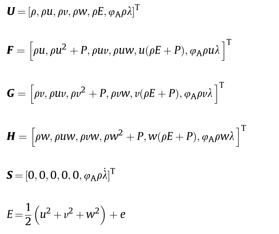
where the switch function φtakes the value 0 for Stage I,and 1 for Stage II.u,v,w are the Cartesian component of the particle velocity in the x,y,z directions.Respectively,ρ is density,P is pressure,E is total energy per unit mass,e is internal energy unit mass.
Stage II needs to research the ignition and detonation of the acceptor charge.When φ=1,the chemical reaction kinetics model is introduced into the governing equations.The most used chemical reaction rate model of condensed explosives is the ignition and growth reaction rate model[19].The model has the form:

where I,G,G,a,b,c,d,e,g,x,y,and z are constants.This reaction rate law models the three stages of reaction generally observed during shock initiation of condensed explosives.
The unreacted explosive and the reaction products are both described by the Jones-Wilkins-Lee (JWL) equation of state.The equation can be written as

where A,B,R,R,C,and ω are constants.
Ideal gas equations of state are used for air

where γ is specific heat constant,generally set to 1.4 for air.
2.2.The numerical method
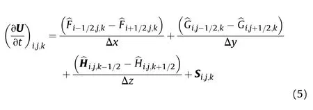
Fifth-order WENO finite difference scheme and third-order TVD Runge-Kutta scheme is employed to discretize Euler equations.WENO finite difference scheme have the advantage of simplicity and lower CPU cost,especially for multi-dimensional problems[12].The semi-discrete scheme is as follows:

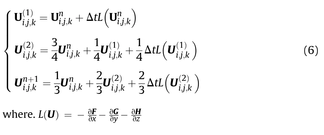
Third-order TVD Runge-Kutta scheme is employed for temporal discretization.This method is very effective for solving hyperbolic problems.
2.3.Interface treatment
The motion of the interface between detonation products,air and explosives is described by the local LSM[20].LSM uses a signed distance function φ(x,y,z,t) to track the interface at any time.The interface is always at the isosurface position where the function is equal to zero.

At the initial state of simulation,the initial value of the symbolic distance function is usually defined as follows

where,d is the distance from the grid node(x,y,z)to the interface.
An advection equation is utilized to advance the interface at each time step

where,u=[u,v,w]represents velocity components of x,y and z direction.The equation can also be written as

This equation also uses the fifth-order WENO scheme and the third-order TVD Runge-Kutta scheme for spatial and time discretization,respectively.
The interface is treated by the Real Ghost Fluid Method(RGFM)[21].The RGFM uses the material states on both sides of the interface to construct and solve the Riemann problem.The result is used to correct the real fluid state of the interface and further correct the virtual fluid state.The multi-substance interface processing flow of RGFM is shown in Fig.1.The solution of the Riemann problem can accurately give the real state of flow at interfaces,thereby reducing the errors.The Riemann problem between material interfaces is established using the equation of state in Section 2.1 and solved by the Harten Lax and van Leer Contact(HLLC)Riemann Solver[17].HLLC is a three-wave model consisted by contact wave and resulting two-star states for the intermediate region of the Riemann-problem solution fan.Due to the RH condition across the shock wave and assuming the pressure is a new parameter,HLLC can easily extend to multi-material interaction with complex equation of state.Moreover,as a result of contact wave estimation,this method has great efficiency and robustness[22].Combined with RGFM and LSM,high-precision interfacial treatment of multi-material fields is realized.This scheme is used to carry out a numerical simulation of A series of near-field explosions,and the free field pressure is consistent with the experimental results[14].
2.4.Data interaction
Stage I and Stage II of the SD are calculated separately by two solver modules,and the data interaction between the two Stage has a great influence on the numerical simulation.Since the two Stages have different grid scales and time steps,to achieve high-precision simulation in the whole process of SD,it is necessary to interpolate the transmitted data.The time step of the explicit finite difference scheme must meet the CFL conditions and is positively correlated with the mesh size.In the SD process,the pressure signal is transferred from Stage I to Stage II,and the data is transferred from the coarse mesh to the fine mesh.To solve the problem of different time steps in the two Stages,time interpolation is needed for the conserved variables of the governing equations.


In order to improve computing efficiency,the code implements parallel computing with Message Passing Interface(MPI).Since the computing area and grid size of the two Stages are different,in order to allocate computing resources reasonably,different schemes need to be used for area division.During data transfer,it is necessary to temporarily combine the data on all nodes on the transfer plane,and then re-parallelize it.In addition,in the case of multi-material,the interface Riemann problem needs to be solved by the HLLC solver during the data transfer process to improve the calculation accuracy.The entire data transfer processing flow is shown in Fig.4.It should be noted that the linear interpolation used here is to improve calculation efficiency.In practice,the use of highorder interpolation methods such as WENO for data transmission does not significantly improve the calculation results,but the efficiency is reduced.Because in the RGFM method,due to the existence of strong discontinuities between two kinds of media,the calculation accuracy of the interface is only at most second order[23].
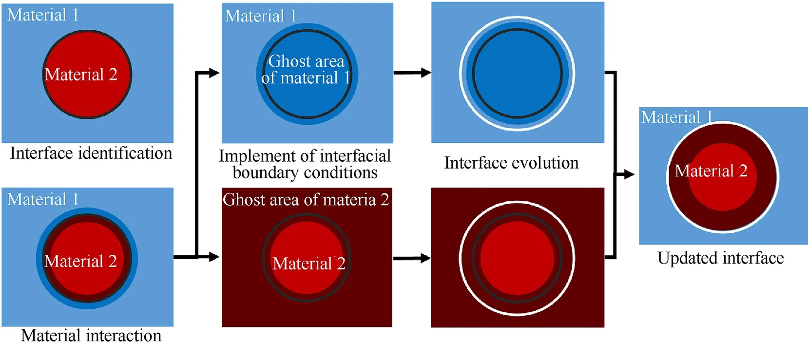
Fig.1.RGMF deal with interface between two media.
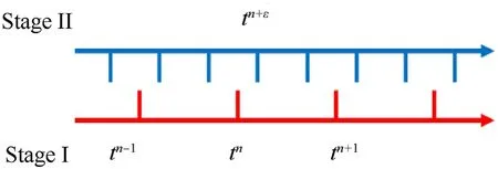
Fig.2.Timeline schematic of Two Stages.
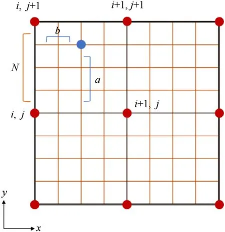
Fig.3.Spatial interpolation of nodes.
3.Numerical simulation of sympathetic detonation
Based on the model and computing method mentioned above,the numerical code of explosives SD is developed.The commonly used Composition B (RDX60%,TNT40%) is selected as the research object,and the numerical simulation of the whole process of SD in the air is carried out.The explosives used in the following simulations and experiments are all uncased charges.
3.1.Numerical model
A three-dimensional model of sympathetic detonation is developed in Fig.5.The magnitudes of length and diameter of the cylindrical charges are respectively 50 mm and 32 mm.The donor charge is coaxial with the acceptor one.Change the stand-off distance l between the two charges to study the reaction state of the acceptor charge.The donor charge is detonated from the left end.Cube grids are used for simulation.The calculation area of Stage I is[400mm×100mm×100 mm],and the calculation area of Stage II is[50mm×32mm×32 mm].The boundaries of Stage I are all set to outflow to simulate the air explosion in wide open space.The related parameters are listed in Tables 1-3 [24].

Table 1.Initial parameters for Comp B charge and air.

Table 2.EOS parameters for Comp B.
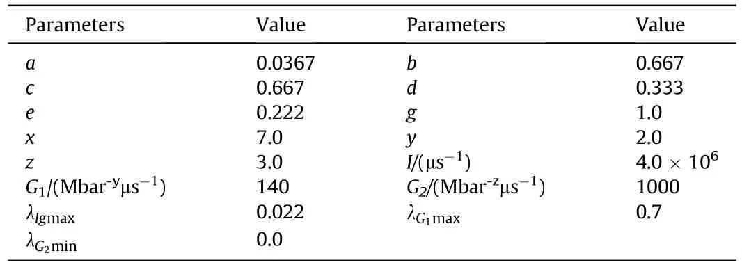
Table 3.Ignition &Growth parameters for Comp B.
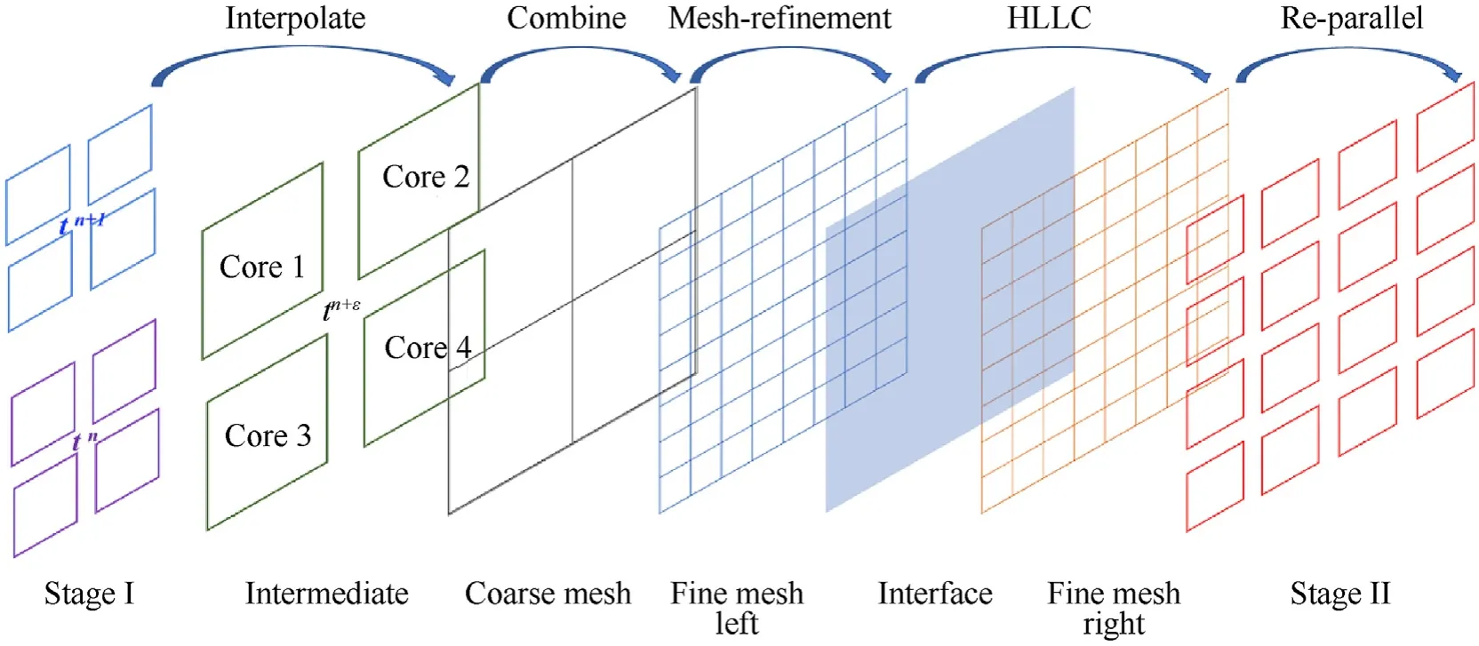
Fig.4.Data transfer processing flow between two stages.
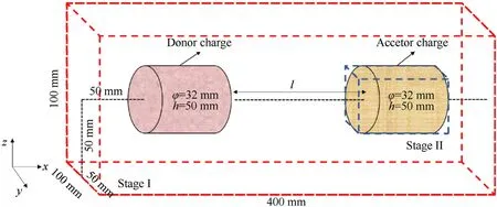
Fig.5.Numerical model of sympathetic detonation.
In the initialization phase,assign values to the area where the donor is located,and this part of the explosive is equivalent to having completely reacted at the initial moment.In the assignment process,in order to describe the direction of initiation,it is simplified as a plane wave initiation.Since the grain diameter is relatively small,this equivalence will not cause large errors.In order to determine the initial value,a 1-D detonation simulation of Comp B is carried out.The algorithm,equations,parameters and meshing are similar to those of Stage II.Input the C-J state to ignite,and record the moment when the detonation wave reaches the end and the explosive reacts completely.Then assign the physical quantity to the Donor according to the distance.This processing ensures that the velocity and pressure inside the Donor are continuous everywhere,and will not interfere with the Riemann solution.The above process is illustrated in Fig.6.
The waves and material interfaces involved in each stage of SD is shown in Fig.7.This process mainly includes two material interfaces.The first is the rarefaction wave formed by the expansion of the detonation products from donor charge,hereinafter referred to as Interface I.The two sides of Interface I are detonation products and air,and the material waves move continuously.Therefore,it is necessary to use the LSM to track the interface,and then use the HLLC solver to calculate the physical state on both sides of the interface.The other is the front face of the acceptor charge,hereinafter referred to as Interface II.When the shock wave propagates into the acceptor charge,the materials on both sides of Interface II are air and explosives.Then the detonation products move to the acceptor charge,and the materials on both sides of Interface II are transformed into detonation products and explosives.Stage II of simulation mainly focuses on the reaction state of the acceptor charge,and the time is very short (a few microseconds),so the expansion of the detonation products is ignored.Therefore,the position of Interface II can be regarded as fixed,and the physical state on both sides can be solved without tracking the movement of the interface.Although the position of the Interface II is fixed,the kinds of materials may change.Therefore,it is necessary to use the Level-Set function of Interface I to judge the material type of interface II,and then select the correct EOS to solve the Riemann problem.
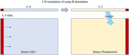
Fig.6.Initial state of donor charge.
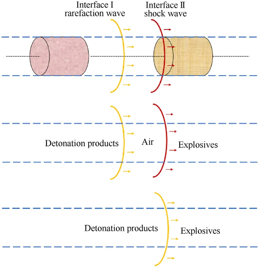
Fig.7.The material interfaces of each stage.
3.2.Convergence verification
Because the calculation accuracy of the numerical scheme is related to the mesh size.More accurate results can be obtained after refining the meshes,but too many meshes will seriously affect the calculation efficiency.Generally,when the meshes are densified to a certain degree,the numerical simulation result tends to a fixed value or fluctuates around the fixed value.
Firstly,convergence verification is performed on Stage I.The calculation area is set to[±0.3 m,±0.3 m,±0.3 m],the center of the 1 kg spherical Comp B is set at[0,0,0],and the rest of the space is air.Firstly,mesh with a side length of 5 mm is used for numerical simulation of the air explosion,and then the mesh size is gradually reduced.The boundaries are all set as outflow boundaries.Set monitoring points on the x-axis at 0.1 m and 0.2 m from the explosion center,and judge the convergence of the program through the pressure time history curve at the location of the monitoring point.The pressure peaks and arrival times calculated at different grid sizes for each monitoring point are shown in Table 4.Fig.8 is the pressure time curve at 0.1 m.Fig.9 is the peak pressurecomparison under different mesh sizes.
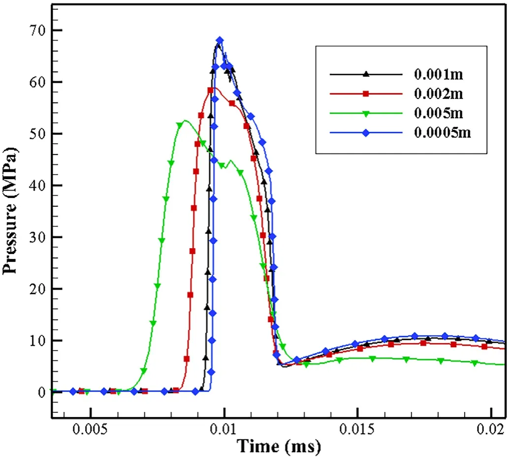
Fig.8.Pressure histories at distance 0.1 m.
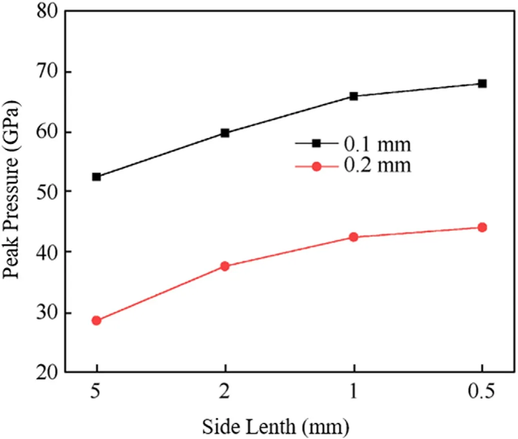
Fig.9.Comparison of peak pressures under different mesh sizes.

Table 4.Peak pressures and arrival times at the monitoring points.
When the total number of mesh is small,the detonation products and shock wave cannot be accurately predicted due to the influence of grid size,and the pressure obtained by numerical simulation is relatively low.From the pressure time history curve and the peak pressure,it can be seen that when the mesh side length is less than 1 mm,the calculation results have very little difference.Therefore,when the mesh is refined to a certain extent(1 mm),the calculation results converge.In order to meet the accuracy and calculation efficiency at the same time,the grid side length should be set to 1 mm.
Similarly,different mesh sizes are selected to verify the convergence of the Stage II.The calculation area is set to[20 mm × 10 mm × 10 mm],the entire calculation area is filled with Comp B,and each boundary is set as the outflow boundary.Input a continuous pressure of 15 GPa propagating in the positive direction of the x-axis at x=0.A numerical simulation of the shock wave initiation of Comp B is carried out with a mesh side length of 0.2 mm,and then the mesh size is gradually reduced.Set monitoring points at 5 mm and 10 mm from the origin on the x-axis.The pressure peaks and arrival times calculated at different grid sizes for each monitoring point are shown in Table 5.Fig.10 and Fig.11 are the pressure time curve at 5 mm and the peak pressure comparison under different mesh sizes.

Table 5.Peak pressures and arrival times at the monitoring points.
From the pressure time history curve and the peak pressure,it can be seen that when the mesh side length is less than 0.05 mm,the calculation results have very little difference.Therefore,when the mesh is refined to a certain extent (0.05 mm),the calculation results converge.In order to meet the accuracy and calculation efficiency at the same time,the grid side length should be set to 0.05 mm.
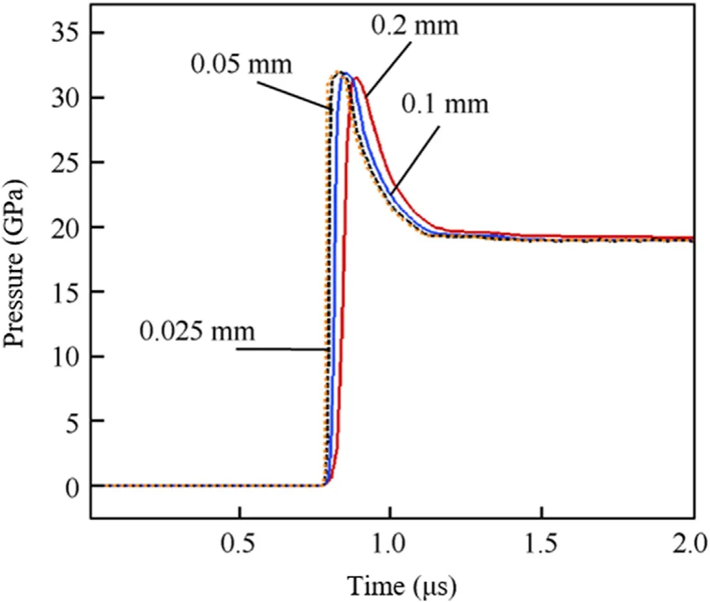
Fig.10.Pressure histories at distance 5 mm.
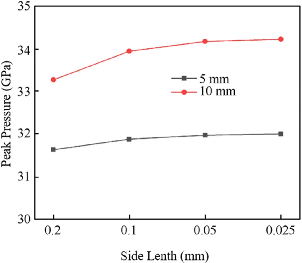
Fig.11.Comparison of peak pressures under different mesh sizes.
3.3.Numerical results and discussion
In experimental research,when probabilities of SD are equal to 100% and 0,gap distances in these two cases are called transmission and safety distances,respectively.Corresponding to the two states of complete detonation and no ignition of the acceptorcharge in the numerical simulation.Different stand-off distances l are selected to carry out the numerical simulation of SD.Six observation points are set up along the central axis of the acceptor charge at equal intervals of 10 mm.Set as points A-F respectively,as shown in Fig.12.This section discusses 4 representative simulation results.
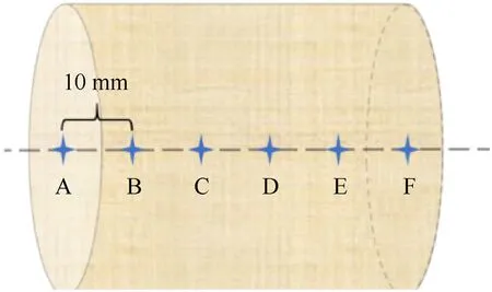
Fig.12.Distribution of observation points.
When l=110mm,the time history curve of pressure and reaction progress at each point in the acceptor charge is shown in Fig.13.The curves all use the time when the impact reaches point A as the initial time.It can be seen from the figure that the incident pressure peak at point A is 1.78 GPa,and the nearby explosives begin to ignite.The shock wave propagates inside the explosives,and the impact pressure continues to rise.It can be seen from the reaction process curve that the explosive at point F reacts quickly and completely.The incident pressure at point E has risen to 3.92 GPa.The pressure at point F jumped rapidly after being impacted,and the peak reached 27.04 GPa.This value is roughly equivalent to the Comp B detonation peak pressure obtained in the experiments [24].It can be calculated from the arrival time of the pressure signal at each point that the average wave velocity of the D-E segment is 3690.00 m/s,the E-F segment is 4807.69 m/s,and the F point exceeds 5000 m/s.This phenomenon demonstrated that sympathetic detonation occurred in this case.
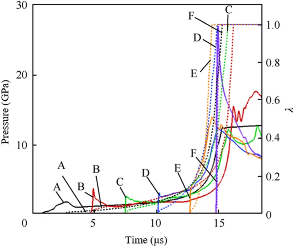
Fig.13.Pressure and reaction progress histories at each point at l=110 mm.
The distribution diagram of pressure and reaction rate at 2.67 μs,8.25 μs,13.23 μs,14.47 μs and 15.71 μs of the dispensed drug column is shown in Fig.14.It can be seen from the figure that there is still a large amount of unreacted explosive in the fired column when the detonation occurs.Mainly distributed in the edge area of the front section of the cylinder.Lots of unreacted explosive remain after the sweeping of initial shock wave,which provides the necessary conditions for the happening of retonation phenomenon.From the reaction process diagrams(d)and(e),it can be observed that the reaction area spreads in the opposite direction of the initial impact.It shows that the retonation phenomenon occurred in the acceptor charge.The retonation wave makes the unreacted explosives after the initial shock wave sweeping continue to react.
When l=120mm,the time history curve of pressure and reaction progress is shown in Fig.15.The incident pressure peak at point A is 1.60 GPa.The incident pressure at each point gradually rises,which is like when l=110mm.The peak explosive pressure at point F reached 18.14 GPa,and the reaction process takes about 0.55 μs Although the growth trend of detonation can be seen,there is no steady-state detonation in the acceptor charge.If the length of the charge is increased,it can grow into a stable detonation.In this case,although sympathetic detonation does not occur in the acceptor charge,the high pressure is still dangerous.
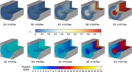
Fig.14.Pressure and reaction rate distribution of the acceptor charge.
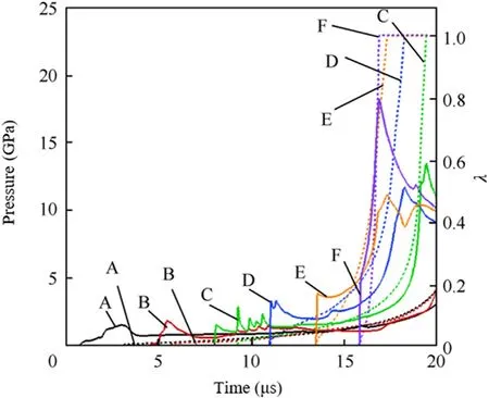
Fig.15.Pressure and reaction progress histories at each point at l=120 mm.
When l=130mm,the time history curve of pressure and reaction progress is shown in Fig.16.The incident pressure peak at point A is 1.44 GPa.Compared with the previous cases,the most difference is that the reaction process of the explosives cannot continue to increase.The reaction rate at point F stays at 0.157,point E is 0.080,point D is 0.025,and the remaining points are lower than 0.01.It can be considered that the explosives have a partial ignition reaction but gradually extinguished.
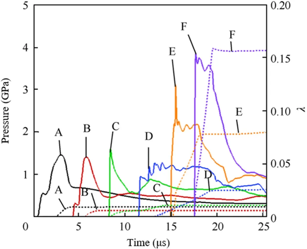
Fig.16.Pressure and reaction progress histories at each point at l=130 mm.
From the pressure trend of each point,it can be found that if the charge is longer,the pressure can continue to rise,and eventually develop into detonation.It shows that the SD phenomenon is not only related to the explosive performance indexes and stand-off distance,but also related to the size of the charge.
When l=140mm,the time history curve of pressure and reaction progress is shown in Fig.17.The incident pressure peak at point A is 1.32 GPa.The pressure curve in this case is obviously different from the previous cases.The pressure at each point is lower than the incident pressure at point A,and the peak incident pressure at point F is only 0.79 Gpa.The energy accumulation in the explosives is lower than the dissipation,and the shock wave gradually weakens in the charge.Only a small amount of explosive is ignited,and the reaction zone has no tendency to grow and spread.Even if the length of the charge is increased,the explosive will not detonate.Therefore,it can be considered that the explosive is safe in this case,and the explosives are not sympathetically detonated.
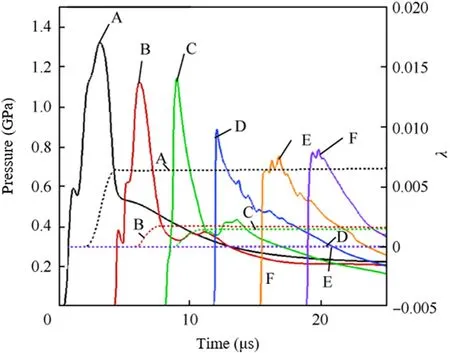
Fig.17.Pressure and reaction progress histories at each point at l=140 mm.
The analysis of the above simulation results shows that,in this case,110 mm is the transmission distances of the Comp B,and a steady-state detonation is formed in the charge.140 mm is the safety distance of Comp B,which will not ignite the explosives.When the distance is between 110 and 140 mm,there are detonation growth trend inside the charges,but the steady-state detonation is not formed in the end.In actual use,this situation is greatly affected by environmental factors,and it is also very dangerous.In the real situation,affected by environmental factors,it is easy to cause SD,so it is also very dangerous.It needs to be paid attention to in safety design.
4.Experimental verifications
In order to verify the results of the numerical simulation,the SD experiment of Comp B is designed in the same situation.The sketch of the experimental arrangement is shown in Fig.18.Composition B was used as the explosive material of the donor and acceptor charges.The density and the mass of the used explosive were 1.74 g/cmand 70 ± 2 g.Denote the stand-off distance between these two charges as l.The donor charge was detonated by the ignition of 8# electric detonators.A detonation wave with high pressure was generated in the explosive.At the same time,a shock wave was also produced and propagated in the air.Subsequently,a shock wave impact was caused since this shock wave arrived at the acceptor charge.A witness plate made of Q235 steel with a thickness of 3 mm was installed under the acceptor charge in order to judge whether it was detonated.The damage level of this plate corresponded to the reaction of the charge.

Fig.18.Experimental set-up.
Results for the sympathetic and no-sympathetic detonations of the acceptor charge were shown in Table 6.The stand-off distance l was changed according the previous result.First,a test for Case 1 with l=45 mm was carried out.The witness plate was damaged and a hole was formed,which indicates that the acceptor charge was detonated.Then the distance was increased by 30 mm.The stand-off distances were respectively increased to 75 mm (Case 2)and 105 mm (Case 3) while the sympathetic detonations were found.Hence,a bisection method was utilized for the next case,with l set to 200 mm (Case 4).The distance was so large that the charge was not detonated.After that,the distances l were respectively diminished to 150 mm(Case 5)and 130 mm(Case6),with the same results in Case 4.Therefore,l was further declined to 110 mm(Case 7).The shock wave impact resulted in the sympathetic detonation of the acceptor charge.Finally,l was increased to 120 mm(Case 8)and the witness plate was not damaged as a result.

Table 6.Results for sympathetic and no-sympathetic detonations of the acceptor charge.
The detailed comparison of results for the damage in the witness plate is illustrated in Fig.19.It is obvious in Fig.19 (a),(b),(c)and (g) that a round hole with a diameter of about 30 mm was formed,with a shear deformation at edges when the stand-off distance is smaller than 110 mm.However,a slight deformation at the center of the plate is caused by the shock impact in Fig.19(d),(e) and (f) when the distance is larger than 130 mm.When the distance is 120 mm in Fig.19(h),there is an obvious circular shear mark at the center of the plate,and the diameter is equivalent to the acceptor charge.
The numerical simulation of the pressure change at point F and the deformation of the witness plate is shown in Fig.20.By comparison,when the stand-off distance is within 110 mm,the explosives have been sympathetically detonated,and the explosives with the separation distance greater than 130 mm have not been sympathetically detonated.When the distance is between the two,part of the explosives reacts and there are still risks of SD.The experiment proved the reliability of the numerical simulation results.
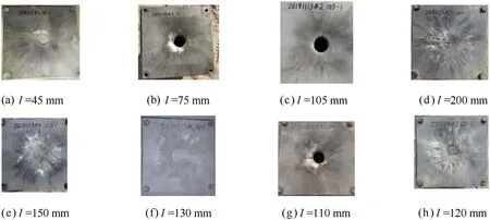
Fig.19.Damage in witness plate.
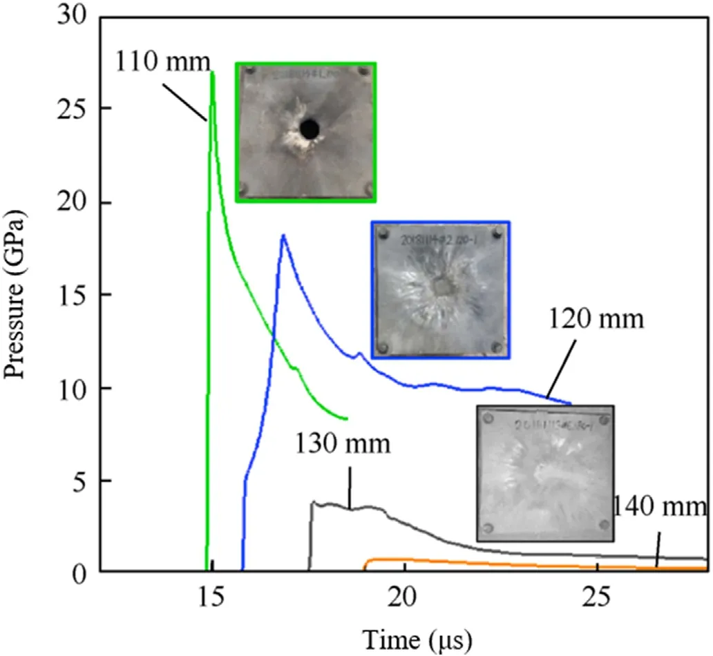
Fig.20.Comparison of pressure at point F and damage in witness plate.
5.Conclusions
A coupled algorithm of LSM,RGFM and WENO scheme is applied to simulate the entire process of sympathetic detonation.A numerical simulation is carried out for the SD in air of Composition B,and the pressure release situation and chemical reaction law of the acceptor charges under different stand-off distances are analyzed.The following conclusions were drawn:
(1) A staged calculation scheme for numerical simulation of the temporal-spatial multiscale problem of sympathetic detonation is proposed.Numerical simulation and experimental verification of Comp B have proved the reliability of the scheme.
(2) The data interaction processing method between the two stages in parallel computing is given.Realize the data transfer of different grid sizes,time steps and material interfaces.
(3) According to the simulation results,when the Comp B charge with a diameter of 32 mm and a height of 50 mm is detonated along the axial direction,the transmission distance and the safety distance are 110 mm and 140 mm respectively
(4) When the distance is between 110 and 140 mm,no steadystate detonation can be formed in the acceptor charge.However,sympathetic detonation is likely to occur due to environmental factors in practice,which is dangerous.
(5) Whether sympathetic detonation can occur is not only related to the explosive performance and stand-off distance,but also to the size of the charge.Especially affected by the propagation distance of the impact in the charge,the longer the distance,the greater the possibility of ignition.Under the charge size set in this paper,the run distance to-detonation of Comp B is 50 mm when sympathetic detonation occurs at the stand-off distance of 110 mm.
The authors declare that they have no known competing financial interests or personal relationships that could have appeared to influence the work reported in this paper.
Funding: This work was supported by the National Natural Science Foundation of China [11732003,U1830139].
杂志排行
Defence Technology的其它文章
- Experimental study on propagation characteristics of rotating detonation wave with kerosene fuel-rich gas
- Adaptive robust control for triple avoidance -striking -arrival performance of uncertain tank mechanical systems
- Experimental study on WFeNiMo high-entropy alloy projectile penetrating semi-infinite steel target
- Numerical investigation of a muzzle multiphase flow field using two underwater launch methods
- Shock wave and bubble characteristics of underwater array explosion of charges
- A micro-chip exploding foil initiator based on printed circuit board technology
