Time Symmetry Analysis of Nonlinear Parity Based on S-P Compensation Network Structure
2022-08-19XIAOWeihaoHUANGXuhong
XIAO Weihao, HUANG Xuhong
(School of Electrical, Electrical and Physics, Fujian University of Technology, Fuzhou, Fujian 350000)
Abstract: The wireless power transmission system based on nonlinear parity time symmetry is a robust system that can maintain high-efficiency transmission at a certain distance. Parity-Time Symmetry (PT symmetry)wireless power transfer system, due to its insensitivity to the position of the coupled resonant coil over a large range, can carry out constant power transfer to the load, and through coupled mode theory The PT symmetrical wireless power transmission circuit with S-P structure is analyzed, and the system has different transmission efficiencies in different coupling intervals, and the transmission effect of the structure at different distances is studied with the change of coupling coefficient. Then, the simulation is carried out by MATLAB and origin software. The final results show that the transmission efficiency does not change with the coupling coefficient in the strong coupling region and can maintain high-efficiency transmission. In the weak coupling region, the coupling coefficient has a great influence on the transmission efficiency of the system.
Keywords: Parity Time Symmetry, Wireless Energy Transfer, S-P Type Structure, Coupled Mode Theory
1 Introduction
Wireless power transmission is a technology that transmits energy by means of electromagnetic fields or electromagnetic waves. With the rapid development of science and technology, more and more electronic products emerge frequently, such as portable electronic products such as notebook computers and mobile phones. While these products enrich our lives,they also bring us troubles. Electronic products are consumables, and they all need to charge the battery.Frequent plugging and unplugging of power cords will not only speed up the service life of electronic products, but also cause wear and tear to the power cords over time, which will also pose a safety hazard to our lives. Some charging cables, wires, plugs, etc.are not completely unified, causing waste of resources and polluting the environment. In special occasions(such as mines and oil exploration), the traditional power transmission method also has potential safety hazards; isolated islands and base stations working on hilltops have many difficulties in using the traditional power distribution method of erecting wires. In addition, in the medical field, there are many examples of artificial intelligence machines replacing failing organs of the human body to delay the life of patients.For machines, there is a need to charge them, and they will be taken out for energy reclassification every few years. But for the patient, this method is undoubtedly cruel. The wireless power transmission technology uses electromagnetic induction coupling for power transmission, which eliminates the danger of frictional electric shock and improves the flexibility of system power transmission. The wireless power transmission technology system has good versatility, high reliability,high safety, reliability and service life, plus the char-acteristics of non-contact and non-wearing, it can meet the power consumption needs of electrical equipment under various conditions, and at the same time the need for information transmission[11]. However, wireless power transmission will have a great limitation on the distance, and the transmission efficiency will decrease as the distance increases, resulting in a waste of power resources. For general wireless power transmission circuits, the transmission distance is relatively short, and the process of transmitting energy is easily changed by the change of the position of the coupling coil[1]. For electronic products,it needs to be placed in a designated position for power transmission. In 2017, the team of Prof. Shanhui Fan from Stanford University proposed the enhanced wireless power transmission based on the principle of nonlinear parity-time symmetry[2]to achieve high-efficiency power transmission. The system is made using the principle of parity-time symmetry.Parity-time symmetry is a concept in quantum mechanics that describes the basic theory of motion of microscopic objects. Generally speaking, symmetry in physics refers to the inherent invariance of a system under specific transformations. Parity-time symmetry is the Invariance under spatial reflection and time inversion[7]. The system used this principle to keep the power transmission efficiency unchanged in the range of about 1 meter in distance[10]. In this paper, based on the nonlinear parity time symmetric circuit of the S-P structure, the circuit is analyzed according to the coupled mode theory. With the characteristics of constant transmission of power due to changes, the position of objects in the strong coupling area can be placed arbitrarily, and the system can still maintain high- efficiency transmission[15]. To a large extent, it solves the problem of poor charging efficiency and waste of power resources caused by wireless power transmission not being placed in the “correct position”[13].
2 Model Establishment and Analysis
The law of parity conservation is expressed as follows: In a system composed of many particles, no matter what changes occur after interaction (including the possible changes in the number of particles), its total parity remains unchanged, then the original is positive, and after the interaction, it remains unchanged. is positive; originally negative, it is still negative after interaction[8]. This law is true for many situations, like the strong and electromagnetic interactions. Therefore, it is considered that the weak interaction is also self-evident. The same is true. Applying the law of parity symmetry to wireless energy transmission to build a transmission circuit based on the S-P structure aims to make the transmission efficiency more efficient and avoid the waste of power. This paper is inspired by the reference [5, 14] that the switching device is used as the energy supply terminal[5,14]The parity time symmetric circuit model based on the S-P compensation structure is shown in Fig.1.The gain circuit is a structure composed of a DC voltage source and a half-bridge inverter, which supplies energy to the transmitting coil. It includes the tuning capacitors C1 and C2 of the transmitting coil and the receiving coil, as well as the internal resistances r1 and r2 existing in the coil, and RL is the load. Ignoring the dead zone and delay time of the half-bridge inverter[9].
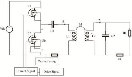
Fig.1 Circuit Diagram of PT Symmetrical WPT System Based on S-P Line Compensation Structure
Vdcis the input voltage source, and
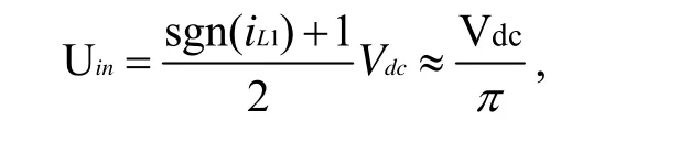
where iL1 is the transmit coil current, and sgn is the sign function.
Coupled-Mode Theory (CMT) is generally used to study the coupling law between electromagnetic waves. Coupled mode theory can truly describe the energy characteristics of WPT systems, and is the basic method to analyze the transmission characteristics of WPT technology[3]. The general S-S type and S-P type WPT system can be regarded as two separate LC oscillating circuits formed by electromagnetic coupling. Considering that the lossless system is only suitable for theoretical analysis, it is an ideal situation.In practical circuits, loss is often needed to ensure parameters. Design reliability. Suppose |a1|^2 and |a2|^2 are the energy contained in the transmitting coil and the receiving coil, respectively; ω1 and ω2 are the natural resonant frequencies of the two coils, respectively;g1 is the net gain of the transmitting coil, and k is the coupling coefficient of the two coils. k = k 1 2 = k 21, the coupled mode model is established according to the circuit:
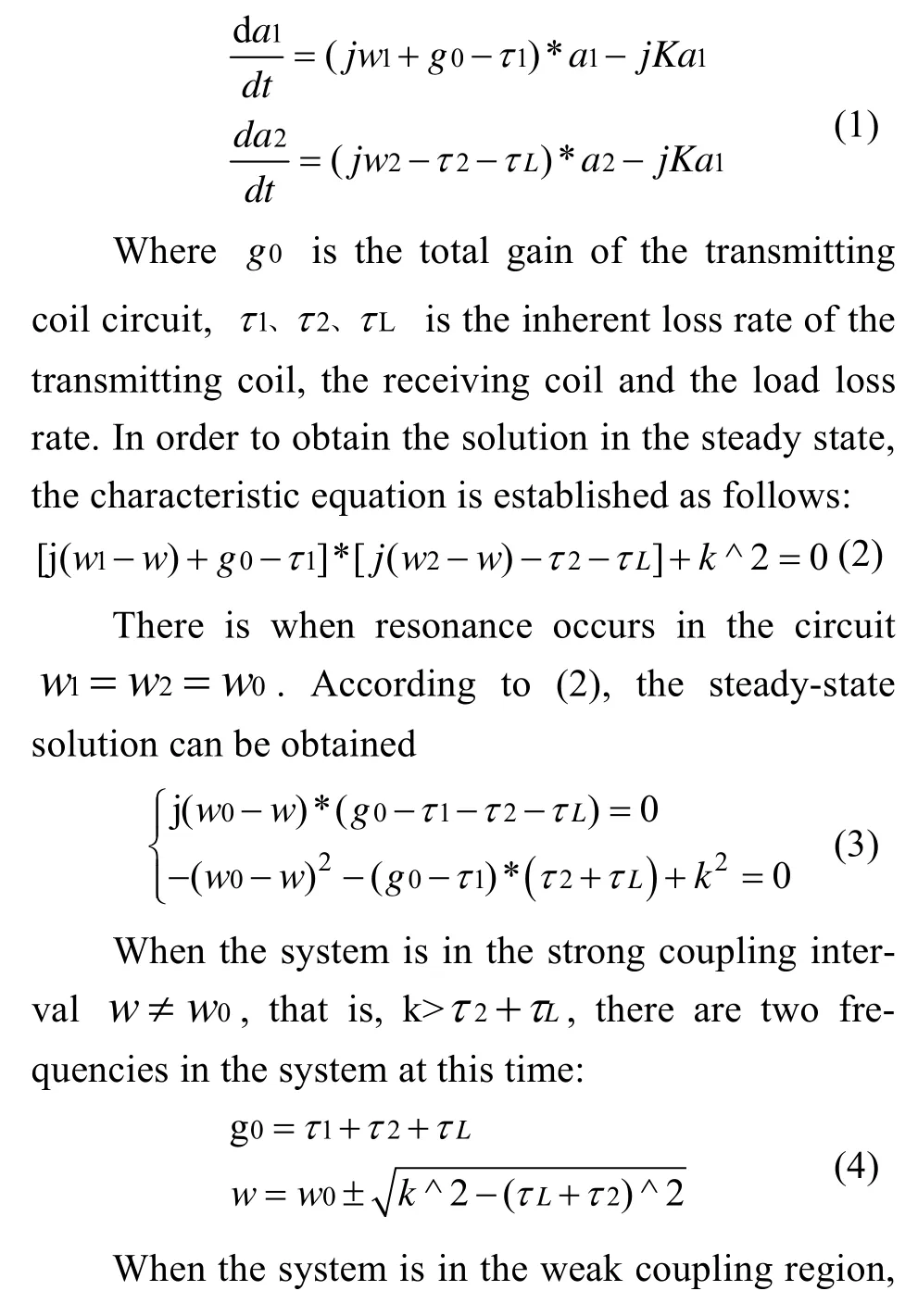
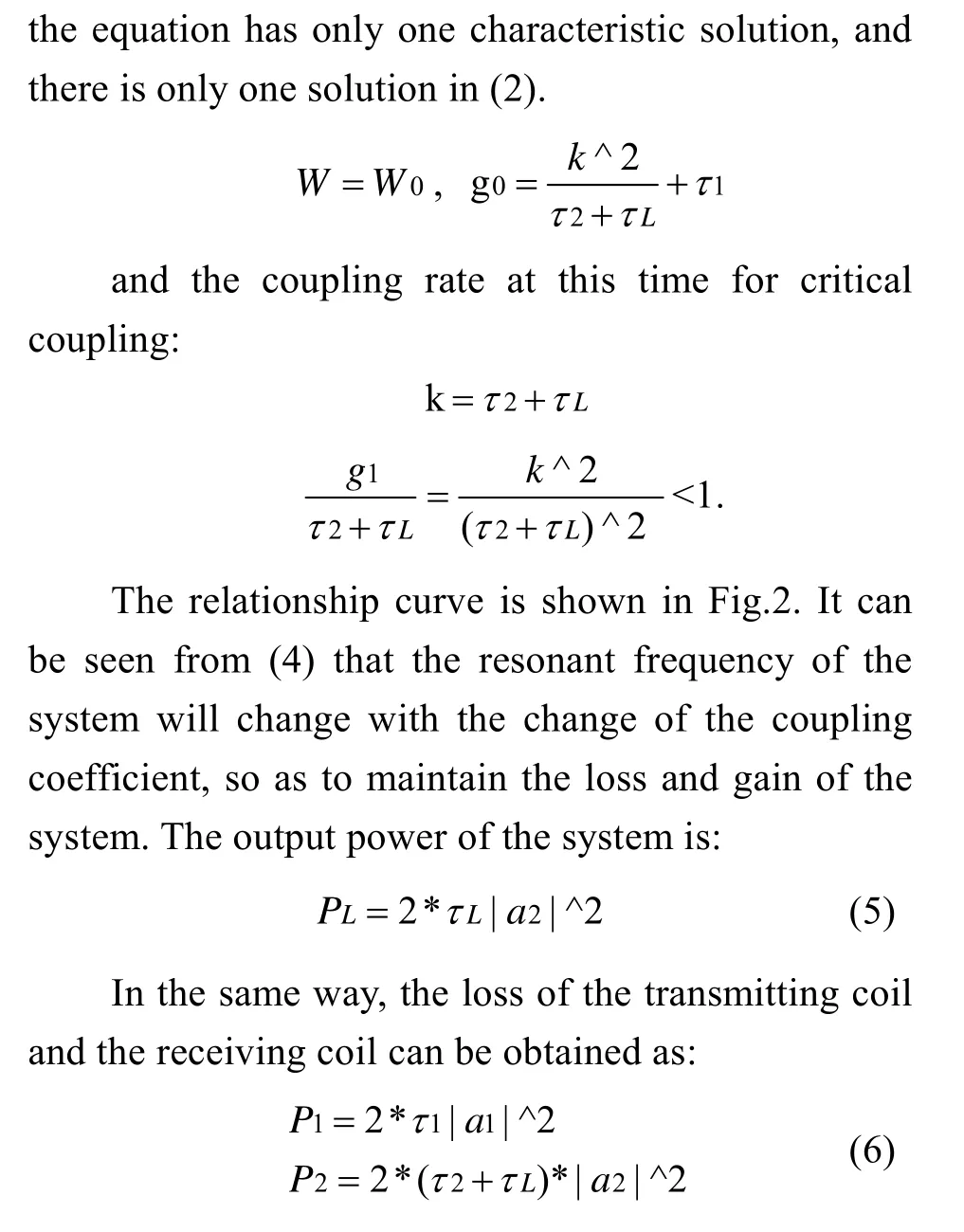
Fig.2 shows the curve fitting diagram of the relationship between the ratio of net gain and loss at the transmitter end and the coupling coefficient in the weak coupling region, and the red line indicates the expected effect. According to the saturation gain mechanism of the system, the operating frequency of the system will change with the change of the cou-pling coefficient in the strong coupling region. The constant efficiency is maintained by changing the gain.The net gain coefficient of the transmitter is equal to the loss coefficient. The values are equal, |a1|/|a2|=1.When the system is in the weak coupling range(k< τ 2 + τL ), the system gain value gradually decreases as the coupling coefficient decreases. At this time,the loss attenuation rate of the receiving end is much larger than the system gain. When |a1| is small to a certain value, the gain circuit will supply energy to the transmitter coil. When transitioning from the strong coupling range to the weak coupling range, the gain at the transmitter does not suddenly decrease as the loss accumulates slowly. It can be seen that when the coupling coefficient k=0.048, the gain deviates from the expected gain. As the power supply circuit finishes power supply, the transmitter gain begins to decrease,and the system transmission efficiency changes with the change of the coupling coefficient.
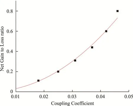
Fig.2 In the Weakly Coupled Region Relationship between g 0 / τL +τ2 and Coupling Coefficient
According to (5), (6) analysis and expansion,according to the formula: efficiency = output power /input power. The transmission efficiency of the following system can be obtained as:
It can be seen from (7) that in the theoretical efficiency calculated by the system, the efficiency in the strong coupling range will be interfered by the loss of the resistance value of the transmitting coil and the receiving coil itself. However, in the actual circuit, the inherent attenuation rate of the transmitting coil and the receiving coil is far Less than the load attenuation rate, the transmitting and receiving coils and the load losses are (8), (9) and (10), respectively. Therefore,the transmission efficiency is close to 1 when it is in the strong coupling interval, indicating that the transmission efficiency at this time is extremely high, and according to the efficiency expression, it can be seen that the efficiency at this time has nothing to do with the coupling coefficient. In practice, according to (7),it can be known that when the system is in the strong coupling region, the transmission efficiency of the system has nothing to do with the coupling coefficient,so that the system is insensitive to the change of the coil position, and when the system is in the weak coupling region, the system is in a state of symmetry breaking, The transmission efficiency varies with the coupling coefficient. The voltage and current characteristics are in the form of segments, and the gain circuit plays different roles at different times.
3 Simulation Analysis and Experimental Analysis
The so-called “parity” can be roughly understood as “left-right symmetry” or “left-right exchange”.According to this interpretation, the so-called “parity invariance” is “left-right exchange unchanged”. Or“mirror symmetry with the original”. According to the left-right symmetry, the “law of parity conservation”can be derived, and some scholars use the one-side(primary side) control method to carry out constant power output[6][13]. In order to verify the high effi-ciency of the nonlinear wireless power transmission process based on the S-P structure in this paper, this paper starts to carry out simulation experiments and analysis based on theory and practice. The parameters are set using the origin simulation parameters as shown in Table 1. The simulation parameters and related calculations can obtain the relevant fitting curve of the coupling coefficient, circuit frequency and circuit transmission efficiency. It can be seen from the figure that the fitting rate of the fitting curve is very high, but it should be noted that theKof the expression in this paper is Coupling efficiency, which is different from the k-coupling coefficient.
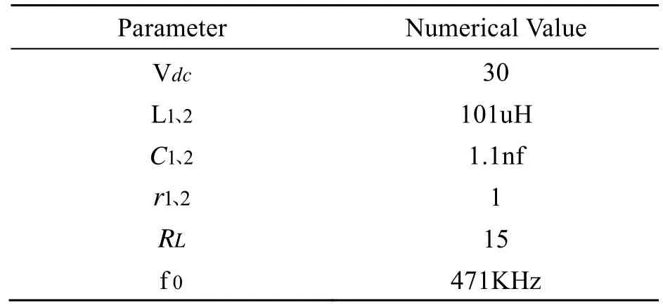
Table 1 System Parameters
here:
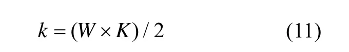
For nonlinear parity time symmetric circuits,there are many factors that affect the transmission efficiency, including analyzing the influence of different frequency bands on the transmission power[4][12]. According to the analysis of the circuit in this paper, the initial primary and secondary resonator frequencies aref0=471kHz, according to (8), (9), (10),(11), the critical coupling coefficient of the circuit is k=0.053, that is, when k>=0.053, the frequency begins to split, and when w =w0, the system gain is maximized. At this time, it is in the strong coupling region,and the efficiency of the system does not change with the change of the coupling coefficient. According tow=2π* f combined formula (4), the relationship between coupling coefficient and frequency can be obtained by analysis as:
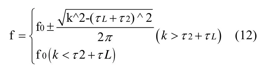
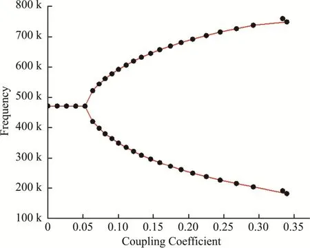
Fig.3 Fitting Curve of the Relationship between the Coupling Coefficient and Frequency Theoretical Value and Experimental Value
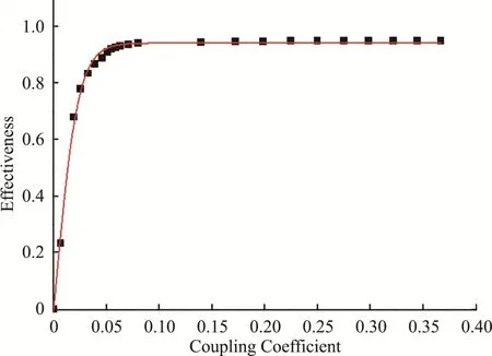
Fig.4 The Fitting Curve of the Relationship between the Theoretical Value and the Experimental Value of the Coupling Coefficient and the System Efficiency
The simulation fitting curve of the relationship between coupling coefficient and system transfer efficiency and frequency is shown in the figure. When the system frequency is greater than 0.05274, it can be seen that frequency splitting occurs in the system, and at this time, the transfer efficiency of the system does not change with the change of the coupling coefficient.In the theoretical analysis, when the critical coupling coefficient is 0.053, the analysis results are consistent,and it can be seen from the figure that in the strong coupling region, the transfer efficiency reaches more than 90%, which realizes the high efficiency of wireless power transmission. Experiments are carried out according to the parameters in Table 1. When keeping the DC input voltage V at 30v, in the strong coupling region, the input voltage is kept at about 10v, the power is around 15W, and the transmission efficiency is 92%, and the PT symmetrical system has a frequency adaptive system. The simulation results are in line with the coupled mode theory.
4 Conclusion
In this paper, the PT-symmetric WPT system circuit based on SP structure is analyzed, and the mechanism of maintaining constant and high-efficiency transmission is analyzed through coupled mode theory. The half-bridge inverter is used as the negative resistance to power the circuit, and the coupled mode theory is used to establish the state Equation expression, parameter design of the load according to the system structure and system simulation analysis verify the high efficiency of the system transmission efficiency and the insensitivity to the change of the coupling coefficient and the correctness of the theory in the PT symmetrical strong coupling region.
杂志排行

Instrumentation的其它文章
- Design of a Logistics Automated Guided Vehicle
- Iris Segmentation Based on Matting
- Research on Hand-eye Calibration Technology of Visual Service Robot Grasping Based on ROS
- Target Path Tracking Method of Intelligent Vehicle Based on Competitive Cooperative Game
- Research on Surface Defect Detection Technology of Wind Turbine Blade Based on UAV Image
- Non-destructive Testing Method for Crack Based on Diamond Nitrogen-vacancy Color Center