Research on Hand-eye Calibration Technology of Visual Service Robot Grasping Based on ROS
2022-08-19LIShengqianZHANGXiaofan
LI Shengqian, ZHANG Xiaofan
(1. School of Electrical Engineering, Guangdong Mechanical & Electrical Polytechnic, Guangzhou 510550;2. School of Automobile and Transportation Engineering Guangdong Polytechnic Normal University,Guangdong Guangzhou 510665)
Abstract: For the hand-eye calibration of the vision service robot, the traditional hand-eye calibration technology can’t be realized which because the service robot is independently developed and there is no teaching device to feed back the pose information of the service robot in real time. In this paper, a hand-eye calibration method based on ROS (Robot Operating System) is proposed. In this method, ROS system is used to accurately control the arm of the service robot to rotate in different positions for many times. Meanwhile, the head camera of the service robot takes images of a fixed point in the scene. Then, the nonlinear equations were established according to the homography matrix of the two images and the position and pose information of the ROS system,and the accurate hand-eye relationship was optimized by the least square method. Finally, an experimental platform is built and the proposed hand-eye calibration method is verified. The experiment results show that the method is easy to operate, simple algorithm and correct result, which verifies the effectiveness of the algorithm and provides conditions for the realization of humanoid grasping of visual service robot.
Keywords: Service Robot, ROS, Least Square Method, Hand-eye Calibration
1 Introduction
At present, robot tracking control technology is a hot and challenging research topic in the field of robotics[1]. This paper introduces the hand-eye coordination grasping and tracking control of vision, which is an innovative robot control technology researching problem. About 80 percent of the information that we get from our interactions with the outside world is through our eyes. Similarly, machine vision system, as an important part of the intelligent work of the whole service robot visual servo and information interaction with the external environment. The intelligent work of the service robot needs to obtain the three-dimensional coordinate information of the external environment object through the vision sensor, and finally convert it to the robot base coordinate system. This is the primary task for the service robot to complete the humanoid grasping working, and the completion of hand-eye calibration is the primary task in this process. The visual sensor obtains three-dimensional coordinate information as the lowest level of the grasping system for the whole service robot, the accuracy of the three-dimensional coordinates is determined by the hand-eye calibration result, which directly determines the success or failure of the grasping work of the whole system. Hand-eye calibration determines the corresponding relationship between the camera coordinate system and the robot end-effector coordinate system.This relationship needs to be obtained through ex-periments and calculations, which is called hand-eye calibration.
At present, the traditional camera calibration method is more, such as Tsai two-step[2], direct linear transformation method[3,4]and the Zhang calibration[5]and so on, these calibration methods have strong applicability, but by making high precision calibration targets, and then take the image to calculation internal and external parameters of camera, this method must have a calibration, but some environment cannot be placed calibration, this limits the application scope of this hand-eye calibration method. Therefore, under the constant exploration and research of researchers, the camera calibration technology is promoted to develop continuously. In 1992, Maybank proposed the self-calibration method[6]. The emergence of self-calibration technology solves the problem of using targets for camera calibration, making calibration more flexible and simpler. In addition, active visual calibration is also a kind of self-calibration method, which obtains images by controlling the camera to do some specific movements so as to calibrate the internal parameters of the camera[7]. The hand-eye calibration technology has also been developed, Literature[8-10]proposes a self-calibration technology of structured light hand-eye system based on active vision, which requires four linearly independent translational motions and two rotation motions. In reference[11,12],calibration based on triorthogonal translational motion and orthonormal operation based on infinite plane homography matrix were also proposed. In literature[13-16], a robot hand-eye relationship calibration method combining multiple calibration methods is proposed. The biggest advantage of this method is to complete the calibration of the camera and hand-eye relationship at one time. All the above calibration methods adopt different hand-eye calibration techniques according to the specific situation of the project.
No matter which hand-eye calibration technology,the robot teaching device needs to feed back the corresponding robot end pose information in a certain state in real time, which makes the service robot of this project unable to carry out hand-eye calibration without teaching device. Therefore, a hand-eye calibration method for visual service robot grasping based on ROS system was proposed in this paper. ROS system is used to replace the teaching device to feed back the end pose information of the service robot in real time, and the least square method is used to solve the established hand-eye calibration relation equations, which simplifies the calibration process and improves the positioning accuracy. It provides effective location information for humanoid grasping and tracking control of service robot, which make the research of restaurant service robot technology is great significance.
2 Problem Analysis
The service robot system collects plate images through the 3D vision subsystem on the head, and performing image processing recognition, stereo matching and 3D reconstruction positioning. Then the 3D space position information of the plate in the robot base coordinate system is obtained through hand-eye coordinate transformation. Fitting tracking trajectory curve to give the desired trajectory. Then, inverse kinematics was used to solve the angle variation of each joint as the expected input. Finally, the controller outputs the control quantity to drive the joint motor to realize the end gripper tracking the desired trajectory to reach the target posture grasp, and complete the task of cleaning up the dinner plate, in which the solution of the hand-eye relationship is an indispensable process.
The hand-eye relationship configuration of visual robots mainly includes eye-in-hand and eye-to-hand two fixing installation modes, The eye on the hand is fixed at the end of the robot and moves with the end of the robot, so the posture relationship between the eye and the end of the hand is fixed and unchanged. In the eye-to-hand workspace, the eye and hand are independent, the eye is fixed at a certain position in the workspace, and the camera(eye) remains stationary, so the impact of vision accuracy which was caused by camera motion shaking is reduced. No matter which hand-eye installation form is adopted, hand-eye calibration must be carried out. Only through hand-eye calibration that can be connected the hand and eye.Therefore, before the robot works, it is necessary to correspond the position and posture of the robot and the vision, and this process is hand-eye calibration.
Eye-to-hand installation is adopted in this paper.Eye-to-hand is beneficial to the experimental researching of the initial development process of the system, which is easy to independently verify the accuracy of the robot control part and binocular vision part, so as to facilitate the troubleshooting of errors in each part. If the fixed connection mode of eye on hand is not conducive to the debugging of the project development process, if the robot movement result doesn’t reach the target point, it is difficult to explain whether there is a problem with the control technology or the inaccurate measurement of binocular vision system, and it is difficult to investigate the cause.
No matter which form of hand-eye relation is adopted, the final essence of the calibration process is to solve the transformation relationship between coordinate systems, as shown in Fig.1.
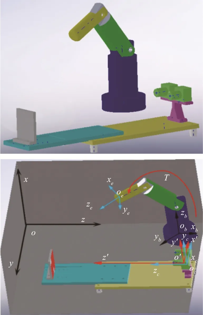
Fig.1 Eye-to-hand Coordination
According to the figure, the coordinate system o′ - x ′ y′ z′ is set as the absolute coordinate system,which is the channel connecting the robot base coordinate system ob-xbybzband the left camera coordinate system oc-xcyczc. The transformation relationship R between the left camera coordinate system oc-xcyczcand the absolute coordinate system o′ - x ′ y′ z′ has been known in the previous working.The next task is to solve the transformation relationship Robbetween the robot's base coordinate system ob-xbybzband the absolute coordinate system o′ - x ′ y ′z′. Controlling the end of the robot to detect each corner of the checkerboard, the robot homogeneous matrix T corresponding to each corner point is recorded, The T can be directly calculated according to the controller's teaching box obtained the corresponding angle of each joint and substituted it into the robot's forward kinematics model. So T is what we know.Therefore, coordinate values of each corner point under the robot base coordinate system can be obtained,as shown in Fig.2.
So according to the coordinate system relations,similarly, the same calculation method is used to solve the transformation relationship between the left camera coordinate system oc-xcyczcand the absolute coordinate system o′ - x ′ y′ z′, The relation of homogeneous transformation matrix between base coordinate system ob-xbybzband absolute coordinate system o′ - x ′ y ′z′ can be obtained, so the coordinate information of the object in the absolute coordinate system o′ - x ′ y ′z′ is transferred to the robot base coordinate system ob-xbybzb. Finally, the target grabbing control operation can be performed in the robot base coordinate system ob-xbybzb, namely, the following equation can be obtained:

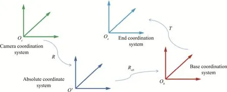
Fig.2 Transformation Relation of Coordination
According to the above analysis, aiming at the problems existing in the hand-eye calibration of the service robot grasping in this project, a hand-eye calibration technology based on the least square method was proposed in this paper.
3 Hand-eye Calibration Technology Based on Least Square Method
3.1 Principle of Hand-eye Calibration
A calibration method of hand-eye relationship based on least square method is proposed, that is not the same as traditional hand-eye calibration methods,because this project robot system under development,and is developed on the ROS system, There is no teaching function like industrial robot which is controlled by the control box to reach a specific position.However, the robot control of this project can only input the corresponding pose coordinate in the ROS system to make the robot run to the target pose. According to the functions of the robot in this project, the hand-eye calibration does not need checkerboard calibration board, which making the hand-eye calibration more flexible. First, in the ROS system, the target pose is randomly input within the robot's motion range to control the robot's motion target pose. At this time, the coordinate pose of the robot's end marking point is the pose information just entered in the ROS system. Then,a 3D camera is used to collect the image of the robot terminal target point, and the position and pose information of the target point in the 3D camera coordinate system is read. In this way, the pose information of any space point in robot coordinate system and 3D camera coordinate system is obtained. According to the closed chain principle of robot and 3D camera, the relation between coordinate information in these two coordinate systems can be deduced, That's the equation between them that satisfies AX =XB. In this way, as many data points are used as possible, and then the least square method can be used to solve and calculate the hand-eye relationship matrix X, and finally achieve hand-eye calibration, as shown in Fig.3.
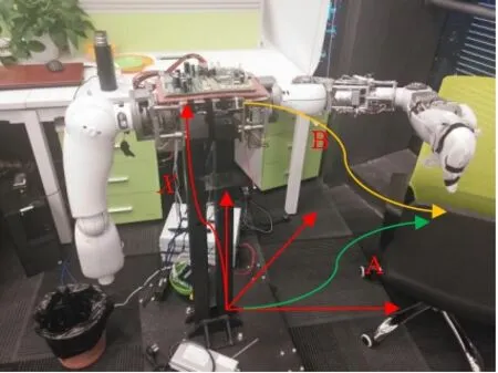
Fig.3 Chart of Hand-eye Calibration Geometry
3.2 Hand-eye Calibration Process Method
The robot communicates with the ROS system and runs the system. The process of hand-eye calibration method is discussed below.
(1) Rotation Matrix R of Hand-eye Relation Calibration
Let point p be the fixed point in 3D space, that is the single fixed point of this calibration, its coordinates in the world coordinate system, robot terminal coordinate system and camera coordinate system are respectively is Xw, XEand Xc. After the robot moves flat bmfrom its initial position, the camera coordinate system and the terminal coordinate system are shifted to obtain the new coordinate system, and the image of the single fixed point p is taken.
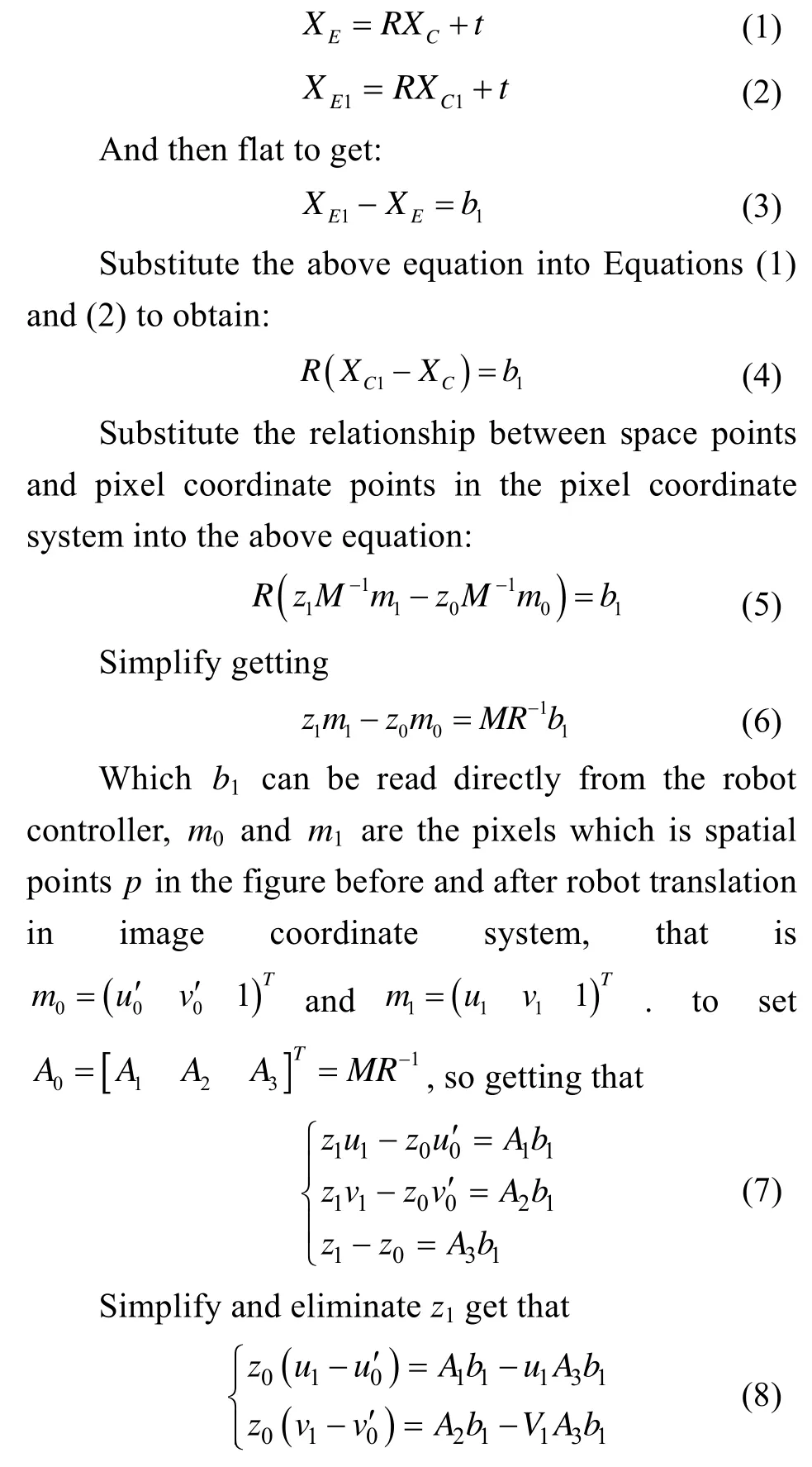
Thus, when the robot is controlled to do translation movement j times, the equations of j groups the above equation can be obtained, which can be written as:
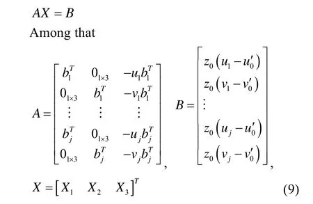
The least square method is used to solve the above equation, to set z0=1, which can solve for X that is one scale factor away from A0. In order to find the true value z0, R is the unit orthogonal matrix, that is RT=R–1,so A0=MR–1will be written in the following matrix form:

According to r1, r2and r3are the unit orthogonal matrix, to use r1, r2and r3to do the dot product or cross product to the left and right of the above formula to solve the camera parameters M1and the rotation part R of the hand-eye relationship matrix. r3=A3,023Tv=A r,
(2) Calibration of Translation Vector t of Hand-eye Relationship
To control the robot to rotate more than twice and take the image of a single fixed point p. After each rotation, the position and pose matrix relationship between the world coordinate system and the terminal coordinate system is as follows:

All parameters of the above formula can be read directly from the robot controller. Since the single fixed pointpis fixed in the world coordinate system,the coordinate relationship between the pointpin the world coordinate system and its image coordinate system after each movement can be obtained, as following
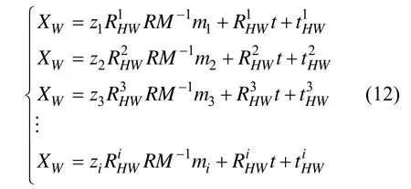
Since that do twice exercises, subtract the above equation in pairs to get:
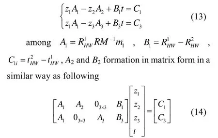
According to the least square method[17], the translation vectortof hand eye relationship and the depth informationziof single fixed point of each pose were obtained.
4 Hand-eye Calibration Test
According to the equation formAX=XBhand-eye calibration method, in order to verify the effectiveness of this hand-eye calibration technology, a hand-eye calibration experimental platform was built. The hand-eye calibration test equipment includes frame,robot system, binocular vision system (3D camera) and computer system. The 3D camera and the robot arm are fixed on the rack, and the relative pose between them can be directly measured with the measurement tool,which provides reference for the verification of the subsequent hand-eye calibration experiment results, as shown in Fig.4. The ROS Kinect version operating control interface is shown in Fig.5, the position information of the end of the arm can be obtained in real time on the interface. After the target is adjusted on the experimental table, the robot's arm is controlled by ROS system to move in different positions for more than eight times, and coordinate pose information corresponding to each pose information in 3D camera coordinate system and target image are collected respectively, as shown in Fig.6. Then, the equations were established for the eye calibration model based on these pose information, and the hand-eye relationship was finally calculated by using the algorithm of this paper, as shown in Table 1.
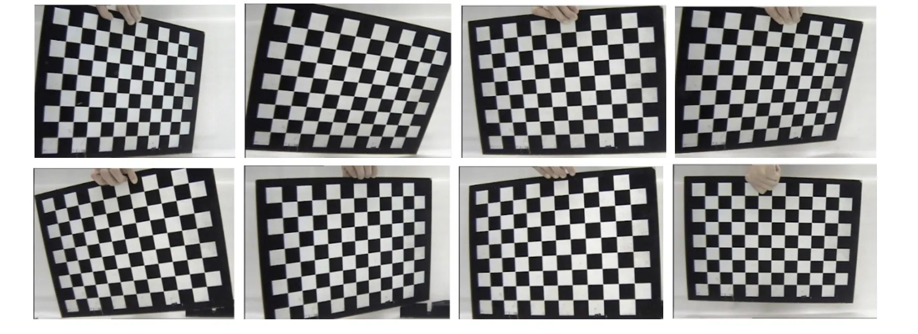
Fig.6 Image of Hand-eye Relationship
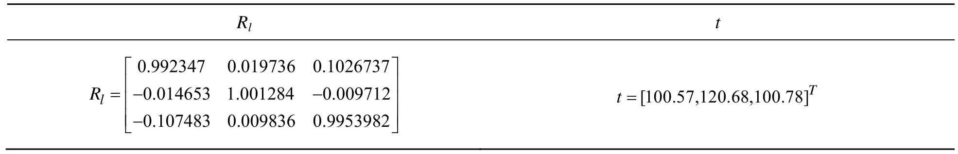
Table 1 Hand-eye Calibration Parameter
According to the above hand-eye calibration position and pose information matrix results, it can be seen from the macro perspective that the end pose of 3D camera and robot are basically the same, and the pose distance between them is roughly correct.
5 Conclusion
This paper focuses on the research of hand-eye calibration technology for service robot visual grasping.Since the service robot in this project is independently developed, there is no teaching device to feed back the pose information of the service robot in real time, so the traditional hand-eye calibration technology can’t be applied. In this paper, a hand-eye calibration method based on ROS (robot operating system) is proposed. To set the trajectory points of the service robot through ROS system, then the equations are established based on the hand-eye relation equation and solved by the least square method. Therefore, a more accurate homogeneous matrix of hand-eye relation is obtained by calibration. Finally, a hand-eye calibration experiment was carried out on an experimental platform. The experimental results show that the proposed algorithm can accurately calculate the pose relation matrix between the hand and the eye, which effectively verifies the feasibility of the proposed method, and provides a foundation for the realization of the grasping control technology of the service robot in the next step.
Acknowledgment
This work was supported by the University-level Funding Projects of Guangdong Mechanical & Electrical college of Technology (No. Gccrcxm-202007).The 2021 Guangdong Provincial Department of education recognized scientific research projects in Colleges and Universities (No.2021KTSCX205) and the 2021 School-level Scientific Research Projects (No.YJZD2021-54).
杂志排行

Instrumentation的其它文章
- Design of a Logistics Automated Guided Vehicle
- Iris Segmentation Based on Matting
- Target Path Tracking Method of Intelligent Vehicle Based on Competitive Cooperative Game
- Research on Surface Defect Detection Technology of Wind Turbine Blade Based on UAV Image
- Time Symmetry Analysis of Nonlinear Parity Based on S-P Compensation Network Structure
- Non-destructive Testing Method for Crack Based on Diamond Nitrogen-vacancy Color Center