Voltage control magnetism and ferromagnetic resonance in an Fe19Ni81/PMN-PT heterostructure by strain
2022-08-01JunRen任军JunmingLi李军明ShengZhang张胜JunLi李骏WenxiaSu苏文霞DunhuiWang王敦辉QingqiCao曹庆琪andYouweiDu都有为
Jun Ren(任军), Junming Li(李军明), Sheng Zhang(张胜), Jun Li(李骏), Wenxia Su(苏文霞),Dunhui Wang(王敦辉),2,†, Qingqi Cao(曹庆琪), and Youwei Du(都有为)
1National Laboratory of Solid State Microstructures and Jiangsu Key Laboratory for Nano Technology,Nanjing University,Nanjing 210093,China
2Hangzhou Dianzi University,Hangzhou,Zhejiang 310018,China
Keywords: voltage control magnetism, magnetoelectric coupling, magnetic anisotropy, ferromagnetic reso
1. Introduction
The study of voltage control magnetism has become one of the most popular research areas due to its potential applications in information storage, sensors and some of the new logical spintronic devices.[1–3]Various magnetic parameters,including magnetic anisotropy, coercivity, saturated magnetic moment and Curie temperature, have been regulated in different systems by different mechanisms, such as charge doping,strain effect and exchange coupling.[4–9]Among them,the multiferroic composite heterojunction composed of ferromagnetic (FM) materials and ferroelectric (FE) materials, which combines a piezoelectric effect and piezomagnetic effect and realizes a magnetoelectric coupling (ME) effect through a strain mechanism,is widely regarded as one of the most likely systems to be applied in practice.[10]In recent years,the ferroelectric single crystal Pb(Mg1/3Nb2/3)0.7Ti0.3O3(PMN-PT),formed by relaxor ferroelectric Pb(Mg1/3Nb2/3)O3(PMN)and ordinary ferroelectric PbTiO3(PT),has been widely used as the piezoelectric substrate in the study of voltage control magnetism based on the strain mechanism due to its large piezoelectric coefficients.[11–16]For example, Liet al.demonstrated a reversible magnetization rotation and manipulated the tunneling magnetoresistance at room temperature in CoFeB/AlOx/CoFeB/PMN-PT.[8]Liuet al.showed nonvolatile resonance frequency tuning in an FeCoB/PMNPT heterojunction.[17]In addition, our research group reported the related work of electric-field control magnetism based on a PMN-PT piezoelectric substrate,such as Co/PMNPT,[18]FePt/PMN-PT,[19]and NiCoMnIn/PMN-PT,[20]which achieved some meaningful results. However,due to the strain asymmetry of the piezoelectric substrate itself, most studies based on PMN-PT can only study the influence of a single tensile(or compressive)strain on the magnetic properties. There are very few studies which can simultaneously explore the different effects of tensile and compressive stresses on the magnetic properties in a multiferroic FM/FE composite heterojunction.
Ferromagnetic resonance (FMR), which is known as the collective spin excitation in ferromagnetic materials, has attracted increasing attention due to its wide potential applications in novel voltage tunable RF/microwave magnetic devices,such as filters,resonators,inductors and phase shifters,as well as possible future spintronic devices.[21,22]Besides the study of magnetization change manipulated by voltage,the voltage regulation of FMR became an important field in the research of voltage control magnetism. According to the LLG equation,[23]the saturation magnetization (MS), magnetic anisotropy field(Hk)and spin wave damping coefficient(α) are the most important parameters used to describe the dynamics of FMR.Permalloy(Py)which possesses high permeability,a high Ms,low coercivity,low magnetic anisotropy and lowα,is a good soft magnetic alloy film suitable for microwave devices.[7,24,25]Therefore, in this work, we prepare the Py/PMN-PT ferromagnetic/ferroelectric composite heterojunctions by magnetron sputtering technology using a permalloy target with the composition ratio of Fe19Ni81and a(011)cut PMN-PT single crystal substrate. Since the substrate has both large tensile and compressive strains, the effects of different strains on the magnetic anisotropy are investigated. In addition,the(011)cut PMN-PT has the characteristics of nonvolatile strain with an applied asymmetric voltage,which provides the possibility of studying the voltage control of FMR.Thus, we demonstrate the effect of non-volatile strain on the ferromagnetic resonance excursion. Our results provide new possibilities for voltage adjustable RF/microwave magnetic devices and spintronic devices.
2. Experiment
A (011) cut PMN-PT single crystal (10 mm×5 mm×0.5 mm in size)was used as the substrate,and an Fe19Ni81film with a thickness of 25 nm was deposited on it by sputtering using an alloy target with the composition ratio of Fe19Ni81.The background vacuum of the chamber was less than 1×10⁻⁵Pa.During the deposition,the substrate was kept at room temperature and the argon pressure was 0.3 Pa. The DC sputtering power was 16 W. To apply a voltage to the PMN-PT, a layer of Au was deposited on the back of the substrate as the bottom electrode and the Fe19Ni81film was directly used as the top electrode.
The surface morphology and film thickness of the samples were measured using a scanning probe microscope(AFM). The magnetic properties of the samples were measured using a vibrating sample magnetometer(VSM),and the strain curves of the PMN-PT substrate were measured by the resistance strain gauge on an electrical measuring platform.During the magnetic measurements, a Keithley 2410 voltage source meter was used to apply a voltage to the PMN-PT substrate. FMR spectra measurements were performed using a coplanar waveguide and electromagnet. The electromagnet provides an in-plane magnetic fieldH, which is perpendicular to the microwave fieldh.
3. Result and discussion
Figure 1(a) shows a schematic diagram of the Fe19Ni81/PMN-PT/Au sample, in which the electric field is applied along the thickness [011] direction of the PMN-PT.The AFM surface morphology of Fe19Ni81film is shown in Fig. 1(b). It is observed that the surface of the film sample is very smooth, in which the average roughness is less than 0.1 nm and the root mean square roughness is less than 0.3 nm.The good surface quality of the film provides a good base for us to investigate the magnetoelectric(ME)coupling effect.
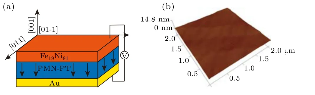
Fig.1. (a)A schematic diagram of a typical Fe19Ni81/PMN-PT/Au sample.(b)An AFM image of the sample with an area of 2 μm×2 μm.

Fig.2.(a)The in-plane strain curve along the[100]direction with symmetric bipolar voltages. The inset shows a schematic diagram of the stress measurement for PMN-PT. (b) Nonvolatile strain curves with different asymmetric bipolar voltages.
Figure 2 shows a typical schematic diagram of the strain measurement of the PMN-PT substrate.An electric field along the thickness of the substrate is applied and the strain gauge is attached to the surface of an electrode to detect the strain. Figures 2(a)and 2(b)show the relationship between the measured strain and the applied symmetric bipolar and asymmetric bipolar voltages in the direction of [100], respectively. It is clear that the strain–voltage (S–V) curve shows a typical butterfly shape for bipolar strain along the[100]direction in Fig.2(a),which is consistent with earlier reports.[26]Two considerable nonlinear tensile strains are observed along the [100] directions near±70 V, which correspond to the coercive field of the PMN-PT substrate.It is noted that the tensile strain around the coercive field is up to+3000 ppm. When we continue to apply the voltage beyond the coercive field, the strain gradually decreases and then increases in the opposite direction.Two compressive strains reaching up to-2000 ppm are observed around the voltage of±250 V. After slowly removing the electric field, the strains gradually decrease and recover to zero, showing volatile behavior (shown as the A state in Fig.2(b)).When an asymmetric bipolar voltage is applied(i.e.the applied positive voltage is larger than the coercive field and the negative voltage is smaller than the coercive field),in contrast to the situation of the bipolar symmetrical electric field,the substrate strain does not return to the initial zero state and shows a nonvolatile residual strain when the voltage is reduced to zero. More importantly,by applying different negative voltages,different residual strain states can be obtained.As shown in Fig.2(b),three different residual strain states of B,C,and D reaching up to+3000 ppm,+2000 ppm,and+1200 ppm are observed in the S–V curves,corresponding to the asymmetric negative voltages of-70 V,-60 V, and-40 V,respectively.Therefore,by precisely regulating the magnitude of the asymmetric negative voltage, stable and different residual strains can be obtained in the PMN-PT substrate.
Since both compressive and tensile strains can be simultaneously obtained with the PMN-PT substrate, two distinct deformations can be induced in the sample. Figure 3(a) illustrates the deformation of the sample at different voltages.When a voltage of-70 V is applied to the sample,according to the S–V curve,the sample is equivalent to being stretched in the direction of[100]and compressed in the direction of[01-1], as shown by the dotted line in Fig. 3(a). When a voltage of+100 V is applied,in contrast to the situation at-70 V,the sample is equivalent to being compressed in the direction of[100]and elongated in the direction of[01-1]. Figure 2 shows the S–V curves for both symmetric and asymmetric bipolar voltages of the PMN-PT substrate in the direction of [100].These two different residual strain states are due to different ferroelectric polarization in the PMN-PT substrate. Electricfield-induced ferroelectric polarization switching between the in-plane direction and the out-of-plane directions is clearly demonstrated in Figs. 3(b) and 3(c). There are eight equivalent directions of spontaneous polarization in the rhombohedral PMN-PT single crystal. For the[011]tangential PMN-PT substrate, there are four spontaneous polarization directions pointing out of the plane,and the remaining four spontaneous polarization directions in the plane.When a symmetric bipolar voltage is applied, the out-of-plane ferroelectric polarization may experience a polarization reversal of 109°and 180°. The direction of the ferroelectric polarization still points out of the plane(such as state A shown in Fig.2(b)),which fails to create residual strain in the plane.As the applied voltage continues to increase,the substrate will produce large in-plane anisotropic biaxial strain. This is caused by the linear piezoelectric effect of the PMN-PT substrate.[27]When an asymmetric voltage is applied to the substrate, the ferroelectric polarization undergoes reversals of 71°and 109°,resulting in the dynamic reversal of the ferroelectric polarization from out-of-plane to in-plane.[17]Thus, a residual strain is obtained in the plane,which corresponds to state B in Fig.2(b).

Fig.3. (a)A schematic diagram of deformation of samples at different voltages. Schematics of domain structures about the (011) PMN-PT under various applied voltages: (b) the residual strain state A with a positive poling state of polarization pointing out of the plane,and(c)the residual strain state B(after applying a negative voltage of-60 V and then switching it off).
To explore the effect of different compressive and tensile strains on the magnetic properties of the sample, the roomtemperature magnetic hysteresis loops for the Fe19Ni81film under different voltages were measured. Figure 4 shows the in-plane magnetic hysteresis loops(M–H)of the sample under different voltages along the[01-1]direction. It is obvious that theMSof the FeNi film is about 840 emu/cm3,which is comparable to the value in the literature.[28]The coercivity of the sample is less than 5 Oe and the initial magnetic susceptibility is very high, indicating typical soft magnetic behavior of the Fe19Ni81film.When a voltage of+100 V is applied to the substrate, not only does the remanent magnetization (Mr) of the sample increase but the magnetic anisotropy also changes considerably, indicating that the magnetization process becomes easier for the[01-1]direction. In contrast, when a voltage of-70 V is applied,the remanence decreases markedly and the magnetization curve becomes a slant loop. The inset of Fig.4 is an enlarged view of the remanence curve, which allows us to see the variation of theMrunder different voltages more clearly. TheMrof the sample increases to 825 emu/cm3under the voltage of +100 V, which is almost the same as theMS. In contrast, theMrof the sample decreases sharply to 450 emu/cm3when a voltage of-70 V is applied. The relative change inMr(Mr(+100 V)-Mr(-70 V))/Mr(-70 V))reaches 83%. It is worth noting that the saturated magnetization of the sample remains unchanged, despite application of the positive and negative voltages,suggesting that different tensile and compressive strains of the substrate have no effect on the intrinsic magnetic interaction of the permalloy. In the study of voltage control of an FM/FE composite heterojunction, it is generally believed that there are two main mechanisms: the strain mechanism, and the polarization charge mechanism. As we know,the electrostatic shielding length of the metal is within 1 nm, while the thickness of the Fe19Ni81film in this work is about 25 nm. Therefore, the influence of the polarization charge at the interface can be ignored for the film. Here,we believe that the voltage regulation effect of our Fe19Ni81/PMN-PT heterojunction is mainly attributed to the strain caused by the piezoelectric effect of the PMN-PT substrate. Figure 3(a)illustrates the deformation of the sample at different voltages. Due to the influence of strain anisotropy,the sample becomes more easily magnetized in the direction of tensile strain while, in the direction of compression strain,the magnetization of the sample becomes difficult. This is in good agreement with our experimental results. Therefore,the variation ofMris mainly attributed to the change in magnetic anisotropy caused by the strain anisotropy.
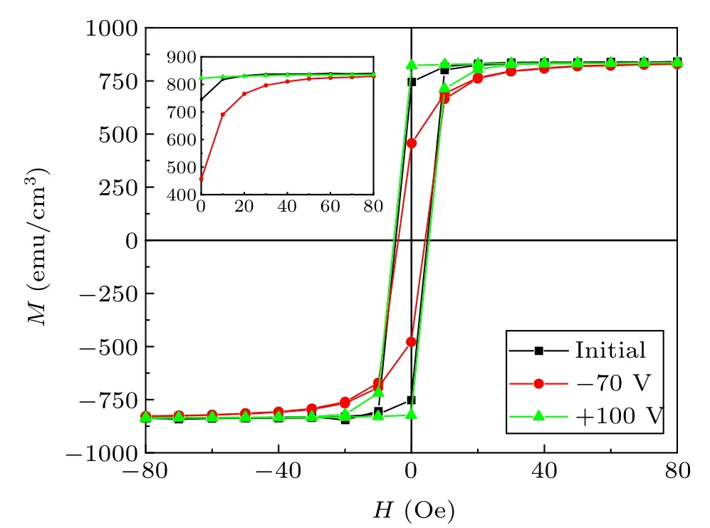
Fig.4. In-plane magnetic hysteresis loops for Fe19Ni81/PMN-PT under different voltages along the [01-1] direction at room-temperature. The inset shows an enlarged view of the Mr curve.
It is known that the magnetic anisotropy of the sample has a great influence on the microwave performance. Therefore, it is meaningful to study the voltage control FMR of the Fe19Ni81/PMN-PT device. If we want to use the voltageinduced volatile strain to manipulate FMR,the voltage needs to be applied to the device all the time, which is disadvantageous to the FMR measurement. Due to the non-volatile properties of the PMN-PT substrate,the non-volatile behavior of voltage control FMR in the Fe19Ni81film can be investigated in this work. During the measurement, the sample is placed face down on a coplanar waveguide and the measured microwave frequencies are in the range of 6 GHz–10 GHz.An electromagnet provides an in-plane magnetic fieldH,which is perpendicular to the microwave fieldh. The FMR measurement is performed in field-sweeping mode,in which the external bias magnetic field is parallel to the sample surface along the[01-1]direction. Figure 5 shows the normalized FMR absorption spectra of samples in the initial state and non-volatile strain states at different frequencies.It is obvious that,with the increasing voltage,the resonance field shifts to the direction of the high fields and the maximum shift of the FMR field(from 1000 Oe to 1070 Oe) is observed with the applied voltage of-70 V at the frequency of 10 GHz.
According to Kittel’s formula,[29,30]the resonance frequency of in-plane ferromagnetic resonance can be described as follows:

wherefis the FMR frequency,γis the gyromagnetic ratio(the value is about 2.8 MHz/Oe),Hris the FMR field andMsis the saturation magnetization. Here,Heffis the effective field induced by the voltage,which could be positive or negative and can be described as:

Here,λsis the magnetostriction constant of FeNi, andσEis the voltage-induced biaxial stress (compressive along [01-1]and tensile along [100] with the applied voltage of-70 V).According to Eq. (1) and the resonance field data measured at different frequencies,the fitting results are shown in Fig.6,in which the experimental data and theoretical calculation fit well in the frequency range of 6 GHz–10 GHz.
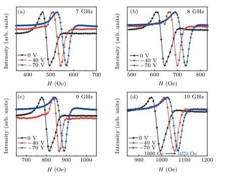
Fig. 5. The normalized FMR absorption spectra of samples in the initial state and non-volatile strain states at different frequencies when the magnetic field is parallel to the [01-1] direction: (a) f =7 GHz, (b) f =8 GHz, (c)f =9 GHz,and(d) f =10 GHz.
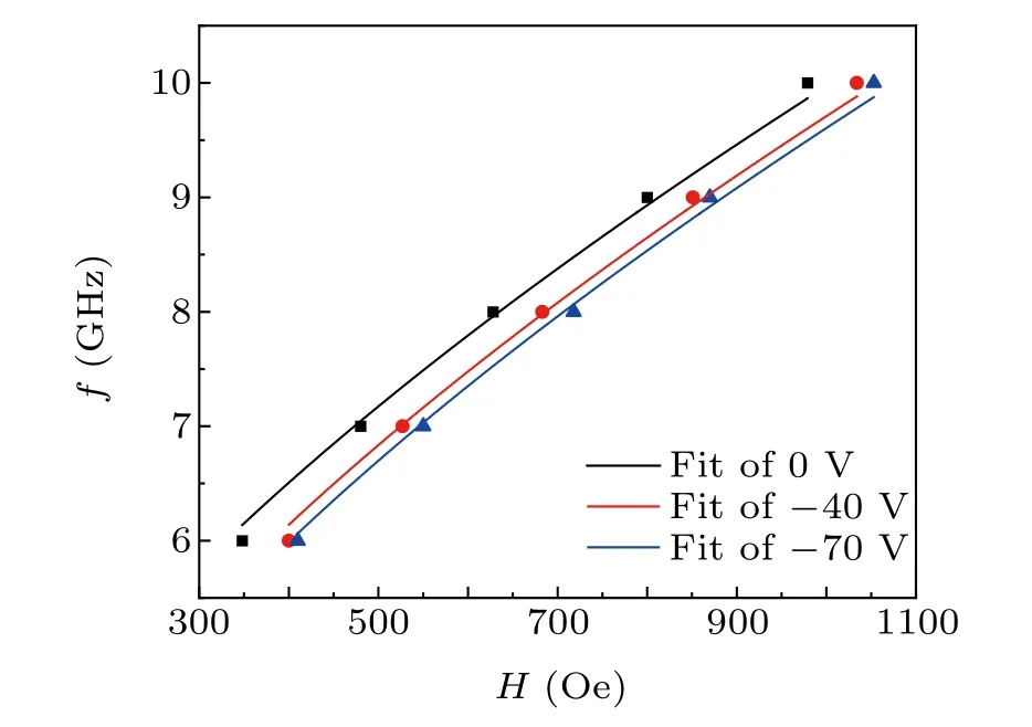
Fig.6.The resonance frequency as a function of the field for Fe19Ni81/PMNPT.The points are experimental data and the solid lines are fitted to Kittel’s formula.
In the Fe19Ni81/PMN-PT heterojunction, after treatment at-40 V and-70 V,nonvolatile compressive strains are then generated along [01-1]. As shown in theM–Hcurves of the Fe19Ni81sample with different strain states, the anisotropy field will be enhanced under the strain. According to Eq.(2),the compressive strain along[01-1]will induce a negativeHeff.As a result,the FMR field shows adjustability and shifts to the higher fields,which can be understood using Eq.(1). Furthermore, it is worth noting that the Fe19Ni81film retains strong absorption over a small linewidth of approximatively 40 Oe,even at the high frequency of 10 GHz,indicating a small magnetic loss of the film. This excellent figure of merit is conducive to the practical application of low-loss magnetic tunable microwave devices,such as filters.
4. Conclusion
The study of voltage control magnetism in Fe19Ni81/PMN-PT composite heterojunctions is demonstrated in this article. By applying a voltage, the PMN-PT substrate can generate volatile or nonvolatile strains which can transfer to the Fe19Ni81film. The magnetic behavior of the Fe19Ni81film is manipulated through the reverse magnetoelectric coupling effect dominated by the strain mechanism. When a positive voltage is applied to the PMN-PT substrate,the magnetization process becomes easier along the [01-1] direction and theMrincreases. When a small negative voltage not exceeding the coercivity is applied,the rectangular degree of the hysteresis loop along the direction of [01-1] becomes lower,and theMrdecreases significantly. This is attributed to the different in-plane anisotropic biaxial strains caused by different voltages. Moreover, we successfully achieve the regulation of the FMR field of Fe19Ni81films by the nonvolatile strain effect of[011]cut PMN-PT substrate and the resonance field shifts to the direction of the high field with the treatment of the voltage. These research results have potential applications in the development of novel voltage tunable RF/microwave magnetic devices.
杂志排行

Chinese Physics B的其它文章
- Real non-Hermitian energy spectra without any symmetry
- Propagation and modulational instability of Rossby waves in stratified fluids
- Effect of observation time on source identification of diffusion in complex networks
- Topological phase transition in cavity optomechanical system with periodical modulation
- Practical security analysis of continuous-variable quantum key distribution with an unbalanced heterodyne detector
- Photon blockade in a cavity–atom optomechanical system