Ballistic impact response of resistance-spot-welded (RSW) doublelayered plates for Q&P980 steel
2022-06-27BohnDongfngHunrnWngninChenFenghuZhou
Bo-hn M ,Dong-fng M ,b ,Hun-rn Wng ,D-nin Chen ,* ,Feng-hu Zhou
a MOE Key Laboratory of Impact and Safety Engineering,Ningbo University,Ningbo,315211,China
b College of Science &Technology,Ningbo University,Ningbo,315211,China
Keywords:RSW Q&P980 steel Ballistic impact Deformation Fracture
ABSTRACT Ballistic impact response of resistance-spot-welded (RSW) double-layered (2 × 1.6 mm) plates (190 mm × 150 mm) for Q&P980 steel impacted by a round-nosed steel bullet (12 mm diameter and 30 mm length)was investigated by using gas gun and high-speed camera system.The RSW specimens were spot welded using a 6 mm diameter electrode face producing a 7.2 mm diameter fusion zone of the spot weld.The ballistic curve and energy balance for the tests of the spot weld of the RSW specimens at different velocity were analyzed to characterize the ballistic behavior of the RSW specimens under bullet impact.The fracture mechanisms of the RSW specimens under bullet impact were presented.For the tests below the ballistic limit,the cracks initiated from the notch-tip and propagated along the faying surface or obliquely through the thickness depending on the impact velocity.For the tests above the ballistic limit,the plug fracture in the front plate of the RSW specimen could be caused by the thinning-induced necking in the BM near the HAZ,while the plug fracture in the rear plate of the RSW specimens may be consist of the circumferential cracking from the rear surface and the bending fracture of the hinged part of material.The effects of the electrode indentation and the weld interfaces on deformation and fracture of the RSW specimens under bullet impact were revealed.For the tests above the ballistic limit,the circumferential fracture from the rear surface of the RSW specimens was always initiated along the interior periphery of the electrode indentation and the crack paths were along the FZ/CGHAZ or CGHAZ/FGHAZ interface.When the circumferential crack also formed outside the electrode indentation,the fracture on the BM/HAZ interface could be found.On the front plate of the RSW specimens,the shear/bending induced cracking from the notch-tip were observed and the crack paths were along the FZ/CGHAZ or CGHAZ/FGHAZ interface.
1.Introduction
In automotive,aerospace,energy and defense applications,the structure with the weldments could be subjected to extreme loadings in service,such as the explosion loadings or the high speed impacts of fragments,which requires the ballistic experiments to investigate the impact behaviors of the structures under such conditions.Over the years,the ballistic impact behaviors of the metallic sheets have been extensively studied in regard to the effects of the bullet nose shape [1-8],the material properties[1,2,7-10] and the target sheet configuration [11-15].In comparison,there is few literature concerning the ballistic responses of the weld part of the sheet structures.Reddy and Mohandas[16]studied the effect of the heat-affected zone softening on the ballistic performance of gas metal arc welded plate.Sullivan et al.[17] investigated the effect of friction stir welding on the knockdown in properties and failure mechanisms of high strength aluminum plate(AA7010-T7651) under the ballistic impact.
Resistance spot welding is one of the most efficient manufacturing processes for joining the sheet metals and has been widely used in the automotive industry.In the past decades,many studies have been carried out focusing on the impact responses of the spot weld in the vehicle crash scenarios.Various dynamic experiments have been carried out using the high speed servohydraulic tensile test machine,the pendulum device,the drop weight system and the Split Hopkinson Pressure Bar [18-22].However,there is no research in the literatures concerning the response of the spot weld under the ballistic impact scenarios,which will be investigated in the present paper.
In previous work[23,24]it was developed a novel experimental method to generate a purely opening loading and the strength of spot welds under the plane shock wave loading was analyzed.The bullet impact tests of the RSW overlapping plates to investigate the ballistic debris impact response at different impact positions were also conducted [25,26].The present study aims to investigate the ballistic impact response of RSW double-layered plates for Q&P980 steel,a 3rd advanced high-strength steels (AHSS) that had been used in the vehicle body components such as A-pillar,B-pillar and side door beam and so on.These components are always connected by the spot welds and the impact resistance of the spot weld in the component is extremely important for the body structure.A gas gun with the high-speed camera system was used to fire the roundnosed cylinder bullet at the spot weld of the RSW specimen perpendicularly.The ballistic curve and energy balance was analyzed for the RSW specimens and an analytical model was developed to characterize the velocity history of bullet during the impact process.The perforation process of the RSW specimen was revealed by the high-speed cameras from the lateral and rear viewpoints and the deformation and failure analysis were conducted with the metallographic cross-section observation.
2.Experimental procedures
2.1.Preparation
The base metal(BM)used in this study was Q&P980 steel,a 3rd advanced high-strength steel(AHSS)possessing both high strength and ductility [27].The chemical composition and mechanical properties of the BM are listed in Tables 1 and 2,respectively.The RSW specimens were spot welded using a pedestal medium frequency DC welding machine (Medar TM-280-D) with the welding cycle presented in Fig.1a and the welding parameters listed in Table 3.Fig.1b shows the quasi-static force-displacement curve of the specimen in the tensile-shear test with the failure mode by the pull-out failure(PF).
Fig.2 shows the cross-section of the spot weld of the RSW specimen.The diameter of the fusion zone (FZ) was 7.2 mm.The heat-affected zone (HAZ) can be divided into two regions:the coarse grain HAZ(CGHAZ)near the fusion zone and the outside fine grain HAZ (FGHAZ).A ‘tongue’ formed between the two plates around the FZ,which was attributed to the high welding current.Due to the higher heat input,the indentation depth was about 0.2 mm in the spot weld,leaving a stair-like surface at the interior periphery of electrode indentation.
Fig.3 presents the micro-hardness profile of the spot weld along the faying surface.It can be seen that the average hardness of the FZ was about 475 HV,which was 140 HV greater than that of the BM(335 HV).A softened zone was observed at the BM/HAZ interface with a hardness decrease of 25 HV comparing to the BM(335 HV).
The RSW specimens were 150×190 mm double-layered plates(2×1.6 mm) jointed with a center-positioned spot weld.The clamped constraints were applied on the top and bottom boundaries and the free constraints were guaranteed on both the lateralboundaries for the high-speed camera observation.The bullet was 12 mm diameter round-nosed cylinder with a total length of 30 mm.It was made of Cr12MoV tool steel,oil-hardened to 58 HRC.The mass of the RSW specimen and the bullet was m≈673.0 g and m≈24.3 g,respectively.The detailed dimensions for the bullet and the RSW specimen are shown in Fig.4.

Table 1 The chemical composition (wt.%) of Q&P980 steel.

Table 2 The mechanical properties of Q&P980 steel.
2.2.Experimental set-up
A gas gun was used to perform the ballistic impact tests.The schematic diagram of the set-up is shown in Fig.5.The gas gun had a 6 m long smooth barrel and a caliber of 12 mm.The bullet was filled into the end of the barrel without the sabot and was fired at the spot weld of the RSW specimen perpendicularly.A PMMA reflective mirror,being a 45with both the RSW specimen and the high-speed cameras,was placed behind the RSW specimen for the rear viewpoint observation.When the bullet perforated the RSW specimen,the reflective mirror would be broken up by the hit of bullet,inducing no damage of the bullet and the ejected plug due to the friable nature of PMMA.Then the bullet and plug would fly into the bullet catcher,which was full of the ragged fabrics to provide sufficient cushioning for the interception of bullet and plug without second deformation.
A short-circuit probe was placed on the muzzle of the barrel to trigger the high-speed camera system (FASTCAM SA1.1) and the cameras were placed perpendicularly to the bullet impact direction.Two arrangements of high-speed camera system were used:the single-position scheme and the dual-position scheme.The single-position scheme was used for the camera 1 to capture both the lateral and rear viewpoints of the scene in one camera,while the dual-position scheme was used for the camera 1 and 2 to capture the lateral and rear viewpoints of the scene,respectively.The typical high-speed camera images of the scene for the each scheme are shown in Fig.6.A synchronizing signal from the camera 1 was used to trigger the camera 2 and the flash lamp when the camera 1 was triggered by the short-circuit probe.In all tests,the camera frame was set as 4×10corresponding to a time interval of 25 μs and the image sizes of the camera 1 and 2 were 512×256 and 384 × 320,respectively.
As shown in Fig.6b,based on the initial impact velocity Vand the relative distance Δd,the time of impact can be calculated as:

where V=(d-d)/(T-T),Tand Tare the time of images from the trigger time and dand dare the corresponding bullet nose displacements.
To reset the time origin from the trigger time to the time of impact,the time T for the each image can be transformed as t:

3.Results and discussion
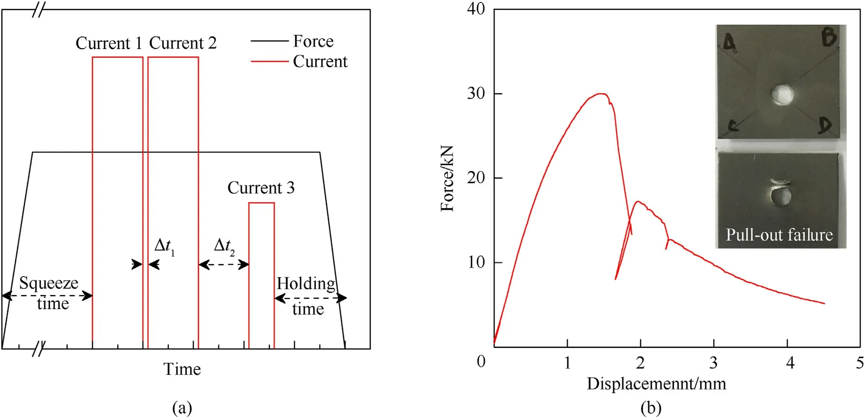
Fig.1.(a) Sketch map of welding cycle of the resistance spot welding for the RSW specimens;(b) The quasi-static force-displacement curve in the tensile-shear test with the crosshead velocity of 5 mm/min.

Table 3 The resistance spot welding parameters of Q&P980 steel.
Typical ballistic impact tests were performed in this study with the bullet initial impact velocity Vin the range of 100-315 m/s.Based on the high-speed camera images,the initial Vand residual Vvelocity of the bullet was achieved and the measured pitch angle θof the bullet after the specimen perforation was also obtained.The recovered RSW specimens were cut along section C-C and were etched by the saturated alcoholic solution of picric acid for the observation of the deformation and crack paths.Some experimental conditions and results for the ballistic impact tests are listed in Table 4.Note that the Test 14 was failed to trigger the high speed camera system and the Vin this test was estimated by extrapolating the pressure-Vcurve from the data listed in Table 4.
3.1.Ballistic curve and energy balance analysis
The experimental V-Vdata for the tests are depicted in Fig.7.An analytical model proposed by Recht and Ipson [28] for thin plates was used to characterize the ballistic curve.

where Vis the ballistic limit velocity and k is the model constant.The value of Vwas determined in the range of 183-200 m/s,which was above the impact velocity not causing the perforation of the specimen as in the case of Test 4,Fig.6a,meanwhile below the impact velocity that caused the specimen to perforate.The least squares method was used to find the best fit of Vand k.The fitted values were V=193 m/s and k=1.95.The fitted curve is shown in Fig.7 by the blue dashed line.

Fig.2.The cross-section of the spot weld of the RSW specimen.
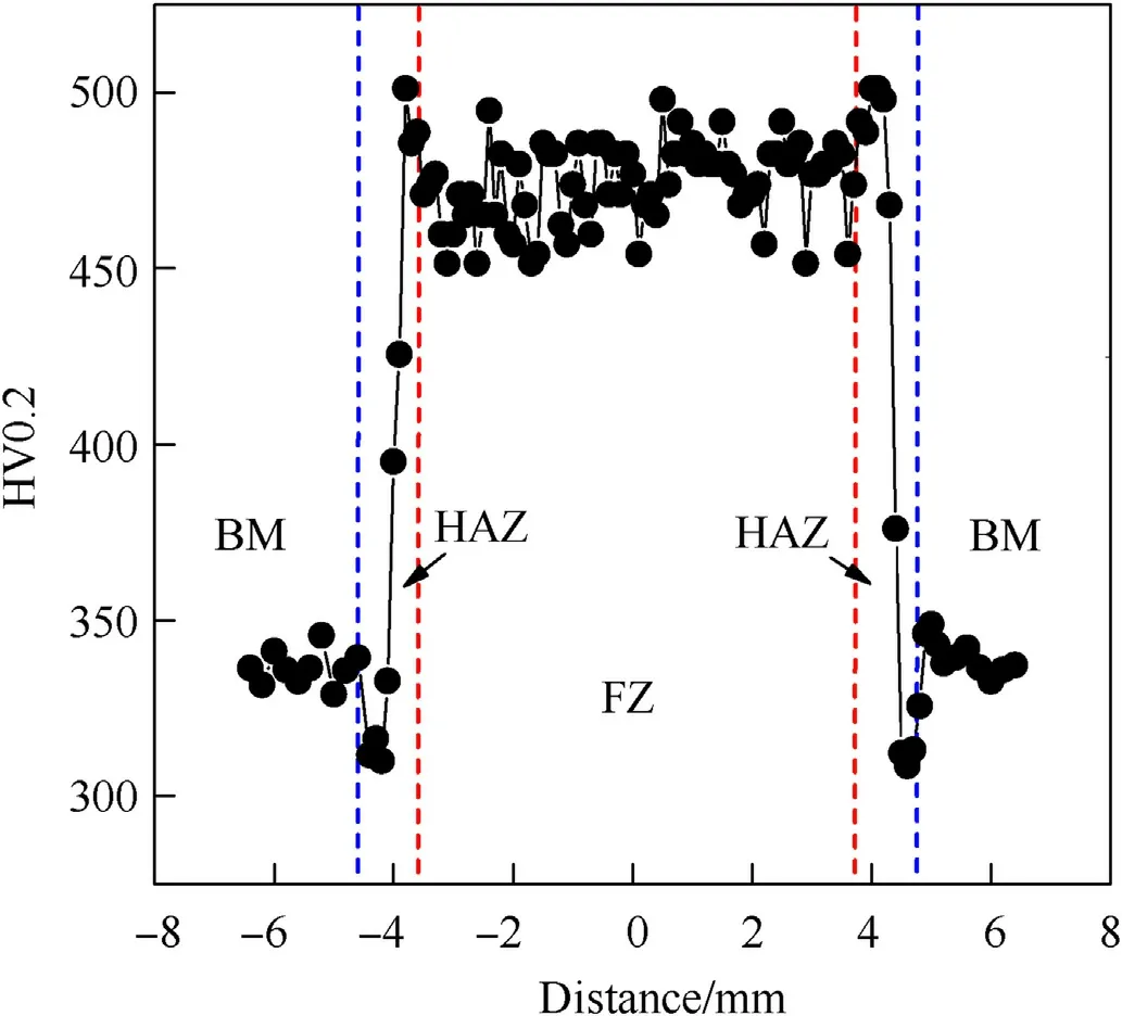
Fig.3.The hardness profile of spot weld of the RSW specimen.
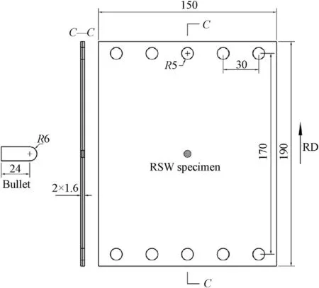
Fig.4.The dimensions of the bullet and the RSW specimen (unit:mm).


For the observation of energy transmission in the bullet impact process,the velocity history of the bullet V(t)was measured based on the high-speed camera images and the corresponding energy absorption history of the RSW specimen W(t)was calculated:

Fig.9 shows the measured velocity history V(t)of the tests.For the tests above the ballistic limit,the velocity histories were ended at the time when the bullet completely perforated the RSW specimen.It can be seen that the duration of perforation decreases with the increasing Vand the perforation process can be generally divided into two stages:in the first stage the V(t)dropped rapidly to a certain velocity just above the Vand in the second stage the V(t)asymptotically approached to the Vwith a slight decrease of velocity.The dashed lines in Fig.9 represent the turning time of the two perforation stages.These two perforation stages were found to correspond with the different deformation and failure processes of the specimens that will be discussed in section 3.2.
An analytical model was developed to characterize the velocity history V(t)during the impact process.The exponential term was introduced in the model to describe the decreasing rate of V(t).The formula is as follows:

where ΔV=V-Vand β is the model parameter that controlling the slope of the V(t)curve.The least squares method was used to find the best fit of β and the fitted curve are depicted in Fig.9 by the solid lines.A good agreement between the experimental data and the analytical curve was achieved in the entire range of impact velocity.
Fig.10 shows the variation of β with the increasing V.The relationship between β and Vcan be approximately formulated as a linear equation.

where a=-2.25×10and b=1.78×10.With the known of the ballistic curve parameters {V,k} and the velocity history parameter β(V)=a+bV,we can express the analytical curve of the W(t)at any given Vin the tests by substituting Eqs.(3),(6)and (7) into Eq.(5).
Fig.11 shows the measured energy absorption history and the analytical curves of W(t)for the tests using the parameter set of{V,k,a,b}={193 m/s,1.95,-2.25 ×10,1.78 ×10}.It can be seen that the established model have a good capacity to predict the energy transmission in the bullet impact process.Comparing to the velocity change of V(t)in Fig.9,the energy absorption process of the RSW specimen was more concentrated in the initial impact stage of~100μs and the absorption rate of energy in this stage seemed to increase with the increasing V.
3.2.Perforation process of the RSW specimens
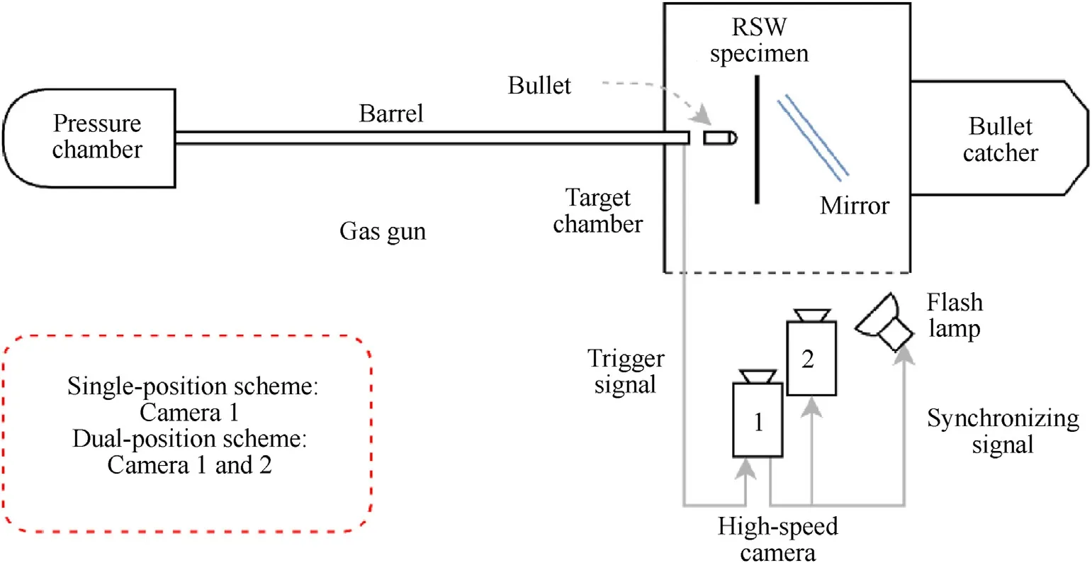
Fig.5.The schematic diagram of the gas gun set-up and the arrangements of high-speed camera system.
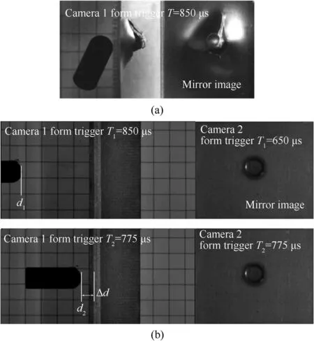
Fig.6.Typical images of the scene for the two arrangements of high-speed camera system:(a)the single-position scheme for Test 4 V0=183 m/s;(b)The dual-position scheme for Test 13 V0=259 m/s.

Table 4 Some experimental conditions and results for the ballistic impact tests.

Fig.7.The experimental results of V0-Vr data for the tests and the fitted ballistic curve by Eq.(3).
Fig.12 presents the lateral viewpoint images for the perforation process of the RSW specimens.The bullet firstly pushed the material of the RSW specimen in front of the bullet nose to form a localized rear bulging with the subsequent cracking around the spot weld,as shown in picture 2 of Fig.13.After that a hole in the specimen formed and enlarged due to the progressive penetration of bullet.Meanwhile,a global deformation was observed in the area adjacent to the impact zone which subjected to plastic membrane stretching and large bending,as shown in picture 3-4 of Fig.13.
As mentioned in section 3.1,the perforation process can be divided into two stages.The high-speed camera images,at the turning time of the two stages marked in Fig.9,has been shown in picture 3 of Fig.13.It can be seen that the turning time corresponded to the completion of bullet nose penetration,indicating that the hole enlargement process finished.Therefore,the major cause of the rapid decrease of V(t)in the first perforation stage was attributed to the bullet nose perforation.The second stage of perforation was corresponding to the perforation of bullet body.As Børvik et al.[31] discussed,for round-nosed bullet the sliding friction was expected between the bullet body and the specimen material.While a small dynamic friction coefficient of 0.05 between the metal surfaces in ballistic impact was reported by Ravid and Bodner [32].So the energy dissipation during this stage by the sliding friction was not significant,which can explain the slight decrease of V(t)in this stage,Fig.9.
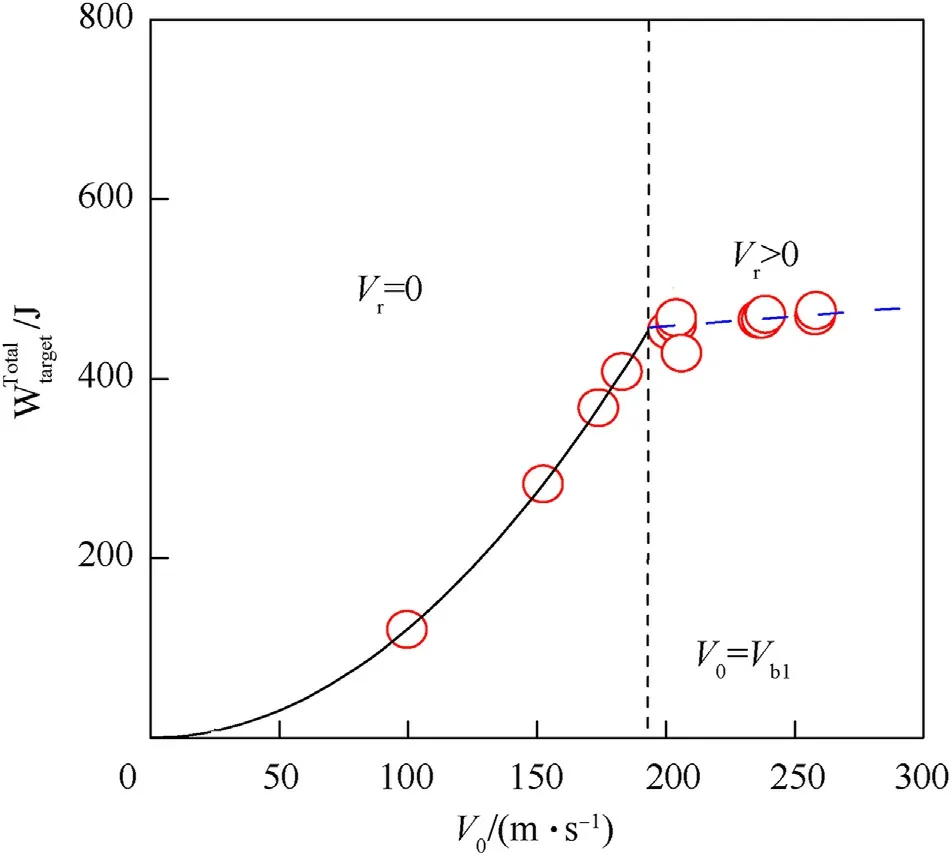
Fig.8.The calculated at the different V0 for the RSW specimens.

Fig.9.Measured velocity history Vbullet(t)of the tests and the corresponding fitting curves by Eq.(6).
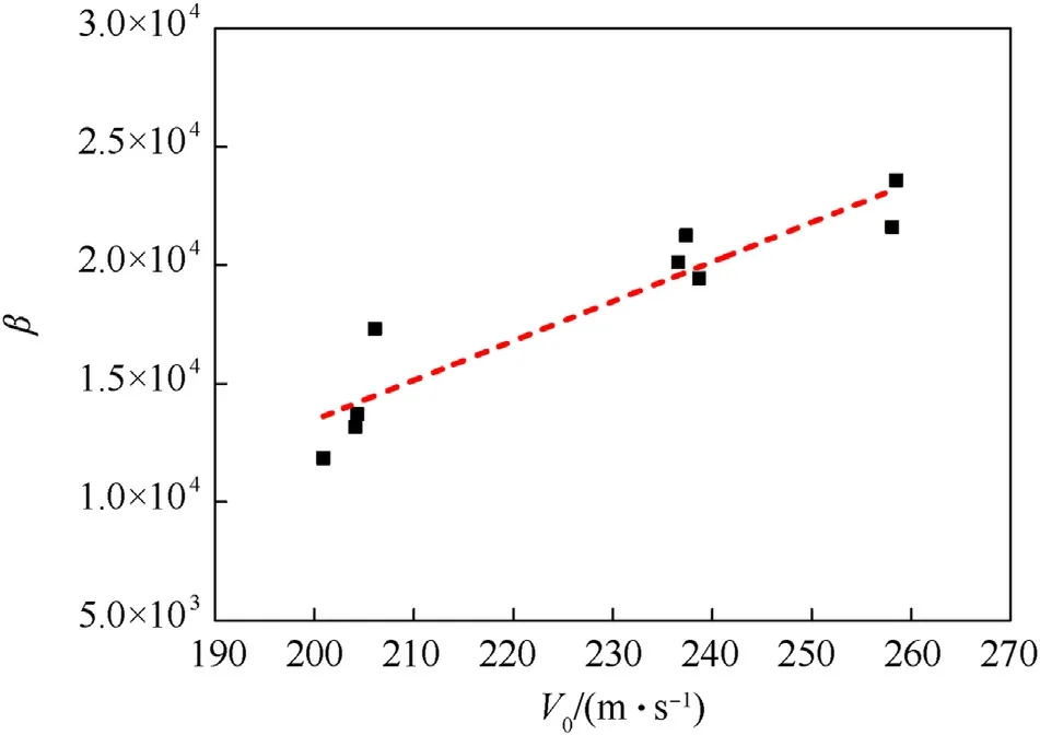
Fig.10.The values of β for different V0 of the tests and the fitting line by Eq.(7).

Fig.11.Measured energy absorption history of the RSW specimen Wspecimen(t)for the tests and the analytical curves given by Eqs.(3),(5)-(7).
Even though the initial impact pitch angle of bullet was small as shown in picture 1 of Fig.12,the rotation of bullet during the perforation process had been observed in all tests.Table 4 lists the measured pitch angle θof bullet after the perforation.
The orientation of bullet rotation seemed to have direct relevance to the asymmetric bulge cracking process.Fig.13 shows the bulge cracking process of Test 5 for the impact velocity close to the ballistic limit,i.e.approximately 4% above the V.As the rear bulging was just formed (picture 2,t=25μs),an incipient circumferential crack was found at the interior periphery of electrode indentation(Fig.2).After that(picture 3,t=50μs),the radial cracks appeared at the hole edge.The rotation of bullet seemed to initiate when the incomplete circumferential fracture formed.As shown in pictures 4-9 of Fig.13,during the perforation some petals formed with the asymmetric extended radial cracks and the petal,connecting with the spot weld,bended more intensely than the others.The radial cracks beside this petal extended more than the others and the result was a loose hoop constraint on the bullet to rotate toward this orientation.
3.3.Fracture mechanisms of the spot weld
3.3.1.Below the ballistic limit
For the tests below the ballistic limit,two kinds of crack propagation paths in the spot weld were observed from the notch-tip.Fig.14 show the different fracture patterns relative to the impact velocity.As reported by Ma et al.[26],the round-nosed bullet impact against the RSW joint brought about an intense shear deformation near the notch-tip.It can be identified by the discontinuity of the fusion line on the faying surface.For the test with V=100 m/s,the shear deformation made the cracks from the notch-tip propagate along the faying surface,as shown in Fig.14a.As Vincreased,the bulging process developed leaving the notch-tip under the intensive bending deformation.With the combination of the shear and bending deformation the cracks from the notch-tip tended to propagate obliquely through the thickness,as shown in Fig.14b and c.
3.3.2.Above the ballistic limit
For the tests above the ballistic limit,the circumferential fracture with the asymmetric extended radial cracks had been observed in all tests as shown in Fig.15.It can be seen that the circumferential fracture was always initiated at the interior periphery of electrode indentation.When the impact velocity increased to~260 m/s,the circumferential crack can also be found outside the electrode indentation,as shown in Fig.15i and j.
Fig.16 shows the ejected plugs in the tests from the front and rear viewpoints.It shows that the major part of plug was the spot weld and some attached material of BM in the front plate was observed in some tests.The plugs were cut along section C-C(Fig.4,also marked by black line in Fig.16b)and the cross-section images of the ejected plugs were shown in Fig.17.
The plugging fracture in the front plate of the RSW specimens could be caused by two different deformation mechanisms:(1)the shear/bending-induced cracking from the notch-tip and (2) the thinning-induced necking in the BM near the HAZ.
·The shear/bending-induced cracking from the notch-tip
This kind of cracking can be observed on the right side of the front plate of the RSW specimens as shown in Fig.17a,b and d.The crack paths were along the FZ/CGHAZ interface throughout the thickness as shown in Fig.17b and d,or along the CGHAZ/FGHAZ interface as shown in Fig.17a.In addition,an arrested crack from the notch-tip can be observed on the left side of the front plate of the RSW specimens as shown in Fig.17d.
·The thinning-induced necking in the BM near the HAZ
Due to the plastic membrane stretching,the plates of the RSW specimens were thinned around the impact zone.The BM with a lower hardness deformed more easily than the weld material and the necking can be observed in the BM near the HAZ.A thinned front plate was detected on the left side of the RSW specimen as shown in Fig.17c and a necking-induced tensile shear fracture was observed on the left side of the RSW specimen in Fig.17b.
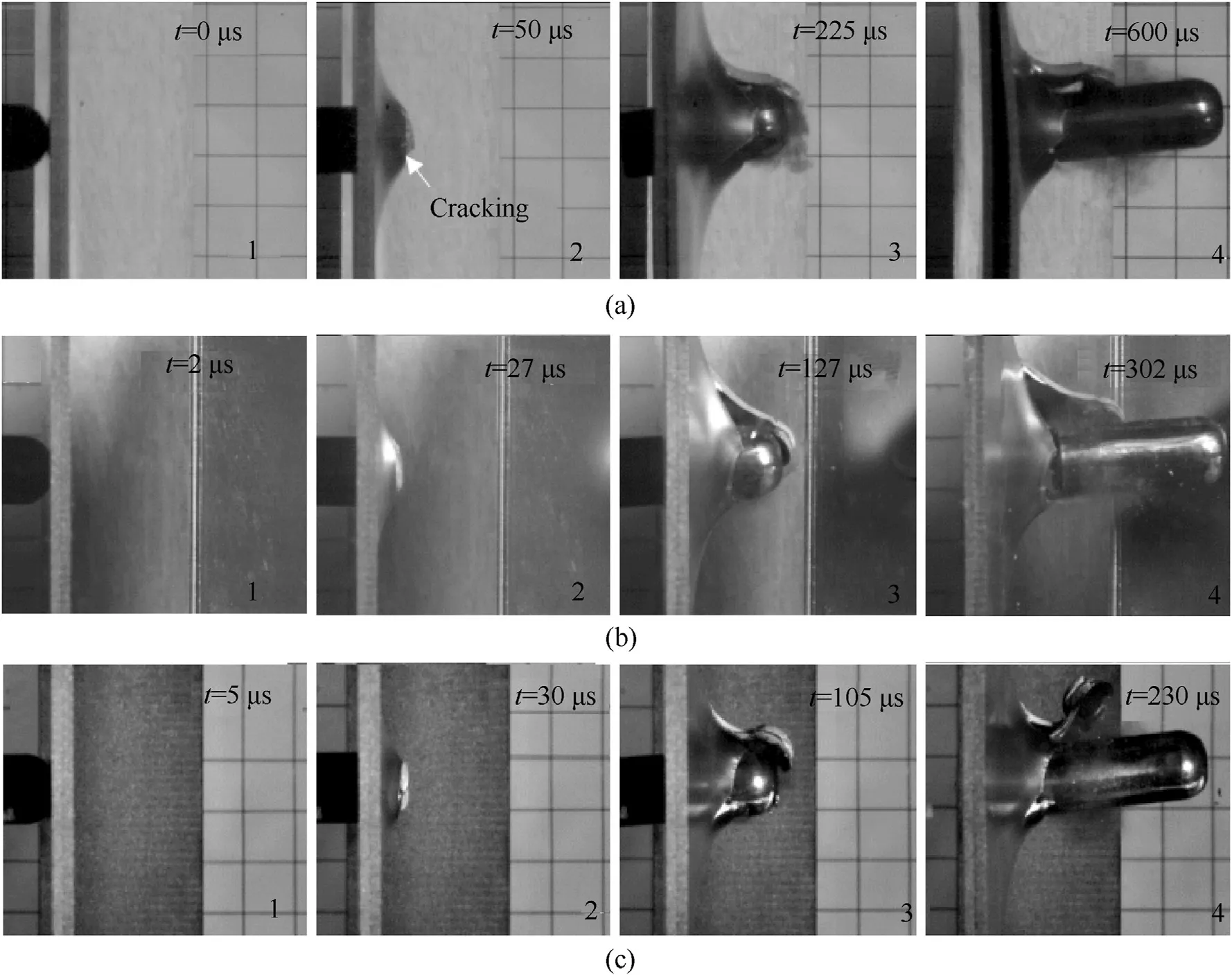
Fig.12.Selection of the high-speed camera images showing the perforation process of the RSW specimens from the lateral viewpoint:(a) Test 5,V0=201 m/s,(b) Test 9,V0=236 m/s,(c) Test 12,V0=258 m/s.
Furthermore,it was observed that this localized deformation had an intense interaction with the cracking from the notch-tip.As shown in Fig.17a,the fracture on the left side of the RSW specimen seemed to be the combination of the necking in the BM of the RSW specimens and the circumferential propagated oblique crack.In addition,as shown in Fig.17b,due to the localized deformation in the BM of the RSW specimen the crack from the notch tip switched the propagation direction to the necking region.
The plugging fracture in the rear plate of the RSW specimens may consisted of two stages:(1)the circumferential cracking from the rear surface and (2) the bending fracture of the hinged part of material.
·The circumferential cracking from the rear surface
With the same deformation mechanism as in the front plate of the RSW specimens,the bending moment and the plastic membrane stretching made the external surface of the rear plate of the RSW specimens under the tensile stress,which can cause the surface cracking owing to the surface imperfections.The interior periphery of electrode indentation was one of the surface imperfection site for the circumferential cracking,where the material experienced a squeeze deformation during the welding process and a stair-like surface was formed in this region,as shown in Fig.2.It was expected that the material in this region had been damaged by the pre-plastic deformation and the stair-like surface would introduce the stress concentration during the perforation.Fracture at the interior periphery of electrode indentation has been observed in Fig.17a,b and c on the right side of the rear plate and the crack paths were along the CGHAZ/FGHAZ interface in Fig.17a and c or along the FZ/CGHAZ interface in Fig.17b.
As shown in Fig.15i and j,the circumferential crack can also formed outside the electrode indentation and the fracture location in this case was observed on the BM/HAZ interface,as shown in Fig.17c on the left side of the rear plate.The hardness profile shows that there exist a soft zone on the BM/HAZ interface which can explain the circumferential cracking at this location.
·The bending fracture of the hinged part of material
As shown in Fig.15,the circumferential cracking in the rear plate had always came up along with the radial cracks,which resulted in the hinged plug attaching to one of the petals.Table 4 lists the mass or the attachment of plug for the tests above the ballistic limit.The possible reason of the ejection mode could be the result of not central impact of bullet.As shown in Fig.16c,on the top view of the bullet in Test 12 and 14,the center of indentation of the spot weld has a slight deflection with the center of the bullet nose.

Fig.13.Selection of the high-speed camera images showing the bulge cracking process of Test 5(V0=201 m/s)from the rear viewpoint.Note that the images had been mirrored to have a normal rear viewpoint.
At the lower V,the plug remain attached to the rear plate after the perforation.While at the higher V,for Test 10 shown in Fig.18,the hinged part of material fractured due to the bending deformation and the plug was ejected with an intense rotation.The location of bending fracture was observed on the BM/HAZ interface as shown in Fig.17a and b on the left side of the rear plate.
4.Conclusions
1.The ballistic curve for RSW doubled-layered plates of Q&P980 steel impacted by a bullet was investigated:The spot weld of specimens (RSW double-layered (2× 1.6 mm) plates(190 mm× 150 mm) of Q&P 980 steel) was impacted by a round-nosed steel bullet (12 mm diameter and 30 mm length)at different velocity.The measured velocity of the bullet V(t)for the tests was given by


2.The fracture mechanisms of the RSW specimens under the bullet impact were indicated.For the tests below the ballistic limit,two kinds of crack propagation paths in the spot weld from the notch-tip were observed.For the Test 1 (V=100 m/s),the shear deformation make the cracks from the notch-tip propagate along the faying surface.As Vincreased,the cracks from the notch-tip tended to propagate obliquely through the thickness.For the tests above the ballistic limit,the plug fracture in the front plate of the RSW specimens could be caused by two deformation mechanisms:(1)the shear/bending induced cracking from the notch-tip;(2) the thinning-induced necking in the BM near the HAZ.While the plug fracture in the rear plate of the RSW specimens may be consisted of two stages:(1) the circumferential cracking from the rear surface;(2) the bending fracture of the hinged part of material.

Fig.14.The cross-section views of some tests below the ballistic limit:(a) Test 1,V0=100 m/s,(b) Test 2,V0=152 m/s,(c) Test 3,V0=174 m/s.
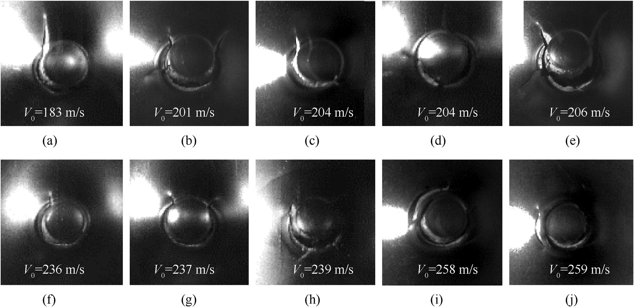
Fig.15.Selection of the high-speed camera images showing the initial circumferential fracture for the tests from the rear viewpoint:(a) Test 4 V0=183 m/s;(b) Test 5 V0=201 m/s;(c)Test 6 V0=204 m/s;(d)Test 7 V0=204 m/s;(e)Test 8 V0=206 m/s;(f)Test 9 V0=236 m/s;(g)Test 10 V0=237 m/s;(h)Test 11 V0=239 m/s;(i)Test 12 V0=258 m/s;(j) Test 13 V0=259 m/s.Note that the images had been mirrored to have a normal rear viewpoint.

Fig.16.The ejected plugs and bullets in the tests:(a)the front viewpoint showing the plug fracture in the front plate of the RSW specimens;(b)the rear viewpoint showing the plug fracture in the rear plate of the RSW specimens;(c)the top and side viewpoints showing the bullets deformations and damage.Note that the black lines marked in(b)indicate the cutting position of the cross-section.
3.The effect of the electrode indentation and the weld interfaces(FZ/CGHAZ,CGHAZ/FGHAZ and BM/HAZ) on deformation and fracture of the RSW specimens under bullet impact were revealed:the circumferential fracture from the rear surface of the RSW specimens was always initiated along the interior periphery of the electrode indentation and the crack paths were along the FZ/CGHAZ or CGHAZ/FGHAZ interface.When the circumferential crack also formed outside the electrode indentation,the fracture on the BM/HAZ interface could be found.On the front plate of the RSW specimens,the shear/bending induced cracking from the notch-tip were observed and the crack paths were along the FZ/CGHAZ or CGHAZ/FGHAZ interface.

Fig.17.The cross section C-C of the ejected plugs of the RSW specimens:(a)Test 10 V0=237 m/s;(b)Test 11 V0=239 m/s;(c)Test 12 V0=258 m/s;(d)Test 14 V0=317 m/s.

Fig.18.Selection of the high-speed camera images showing the plug ejection process of Test 10(V0=237 m/s)from the lateral viewpoint:(1)the hinged plug;(2)fracture of the hinge;(3) plug ejection;(4) plug rotation.
This work was supported by the National Natural Science Foundation of China,China under the grant No.11372149 and K.C.Wong Magna Fund in Ningbo University.
The authors declare that they have no known competing financial interests or personal relationships that could have appeared to influence the work reported in this paper.
杂志排行
Defence Technology的其它文章
- Effect of porosity on active damping of geometrically nonlinear vibrations of a functionally graded magneto-electro-elastic plate
- Theoretical predict structure and property of the novel CL-20/2,4-DNI cocrystal by systematic search approach
- Effect of different geometrical non-uniformities on nonlinear vibration of porous functionally graded skew plates:A finite element study
- Manipulator-based autonomous inspections at road checkpoints:Application of faster YOLO for detecting large objects
- Penetration and internal blast behavior of reactive liner enhanced shaped charge against concrete space
- Failure investigation on high velocity impact deformation of boron carbide(B4C)reinforced fiber metal laminates of titanium/glass fiber reinforced polymer
