Design and motion analysis of reconfigurable wheel-legged mobile robot
2022-06-27ShuoZhangJiantaoYaoYingbinWangZishengLiuYundouXuYongshengZhao
Shuo Zhang,Jian-tao Yao,Ying-bin Wang,Zi-sheng Liu,Yun-dou Xu,Yong-sheng Zhao
School of Mechanical Engineering,Yanshan University,Hebei,China
Keywords:Mobile robots Scissor mechanism Kinematics ADAMS simulation Obstacle surmounting
ABSTRACT An adaptive wheel-legged shape reconfigurable mobile robot,based on a scissor-like mechanism,is proposed for an obstacle detecting and surmounting robot,moving on complex terrain.The robot can dynamically adjust its own shape,according to the environment,realizing a transformation of wheel shape into leg shape and vice versa.Each wheel-legged mechanism has one degree of freedom,which means that only the relative motion of the inner and outer discs is needed to achieve the transformation of the shape into a wheel or a leg.First,the force analysis of the conversion process of the wheel-legged mechanism is carried out,while the relationship between the driving torque and the friction factor in the non-conversion trigger stage and in the conversion trigger stage is obtained.The results showed that the shape conversion can be better realized by increasing the friction factor of the trigger point.Next,the kinematics analysis of the robot,including climbing the obstacles,stairs and gully,is carried out.The motion of the spokes tip is obtained,in order to derive the folding ratio and the surmountable obstacle height of the wheel-legged mechanism.The parameters of the wheel-legged structure are optimized,to obtain better stability and obstacle climbing ability.Finally,a dynamic simulation model is established by ADAMS,to verify the obstacle climbing performance and gait rationality of the robot,in addition to a prototype experiment.The results showed that the surmountable obstacle height of the robot is about 3.05 times the spoke radius.The robot has the stability of a traditional wheel mechanism and the obstacle surmount performance of a leg mechanism,making it more suitable for field reconnaissance and exploration missions.
1.Introduction
Mobile robots have been widely used in rescue,reconnaissance,military and other fields.According to the mobility mode,it can be roughly divided into five categories:wheel type,foot type,track type,wheel-track type and wheel-legged type [1-4].The characteristics of each mobile mechanism are different.Wheeled robots can move quickly,smoothly and save electricity on flat terrain,but they have poor obstacle surmounting ability.The foot-type robot has better obstacle-climbing performance and agile moving ability on rough terrain,but its motion speed is low.The tracked robot has good obstacle-climbing performance and moving speed,which,however,requires a lot of energy.The wheel-legged type mobile mechanism combines the characteristics of wheel type and leg type mechanism,demonstrating good mobility and obstacle overcoming performance [5],while the energy consumption is relatively low.Therefore,the robots based on wheel-legged mobility mechanism carry high research significance and have attracted the attention of domestic and foreign scholars [6].
Chen S C et al.[7]proposed a new type of four legged/wheeled deformable mobile robot,named Quattroped and it can realize shape transformation through a unique mechanism.Chen W H et al.[8]proposed a robot named TurboQuad,based on Quattroped.The new wheel-legged mechanism,not only maintained the concept adopted by its predecessor,but also provided a fast and smooth wheel-legged morphing function from a design viewpoint.RHex series of robots[9],invented at the university of Michigan in the United States,are bionic rod-legged constructions,based on the motion characteristics of cockroaches and demonstrated a strong obstacle jumping ability.D.Y.Lee et al.[10]proposed a deformable wheeled robot based on an origami-like structure.
In China,the research of wheel-legged robots started late,but it has also obtained an abundance of useful results.Zhu JianMin et al.[2]proposed a wheeled stair-climbing mobile robot.Luo Yang et al.[3]suggested a wheel-legged robot with simple structure and good obstacle surmounting abilities,named Rolling Wolf.Sun ZhiBo et al.[11]described a folding steering six-wheeled leg swing arm luffing robot.He YanYing et al.[12] creatively proposed a two-wheeled mobile robot with deformable multi-mode body,which can travel on steps and soft ground by integrating a 6 R mechanism.Bai Long et al.[13] demonstrated a new deformable wheel-legged robot,named Land Demon Fish (LDR).Yang Chun put forward 4 kinds of solutions utilized link mechanism to improve obstacle capability,which are preliminarily carried on by institution selection[14].Guo YunLong et al.[15]proposed a rigid-flexible hybrid parallel obstacle surmounting robot.Tian Run et al.[16] put forward a new type of wheeled robot,based on a 3-spoke wheel-legged mechanism,which can climb stairs and steps and demonstrates a kind of cushioning and damping function.
In this paper,wheel-legged robots operating in complex environments,such as post-disaster areas,are studied.In order to make up for the shortcomings of existing wheel-legged robots,such as low folding ratio and poor obstacle climbing ability,an adaptive wheel-legged mobile reconnaissance robot,based on the scissor mechanism described in Ref.[17] and the shape reconfigurable mechanism presented in Refs.[18,19],is proposed.The rest of the paper is structured as follows.In section 2,the design process of reconfigurable mechanism of wheel-legged configuration is introduced.The process of the force analysis of wheel-legged mechanism transformation is introduced in section 3.The kinematic analysis and research on obstacle surmounting performance of scissor type branched chain leg are discussed in section 4.In section 5,the ADAMS simulation and prototype experiment are used to verify the rationality of the robot design and the obstacle surmounting performance,providing a theoretical foundation for the development of this kind of robot.Finally,the paper is concluded in section 6.
2.Design of reconfigurable mechanism of wheel-legged configuration
2.1.Concept design
The virtual prototype of the wheeled shape of the wheel-legged robot is shown in Fig.1.The robot consists of two symmetrical adaptive wheel-legged mechanisms and a body.The driving motor,MCU and battery are placed on the lower plate.The upper plate is connected to the lower part through copper pillars and it accommodates a camera,a temperature-humidity sensor,a sound collector,a 4G module and other sensors.The lower plate provides some support for the robot to climb over obstacles.
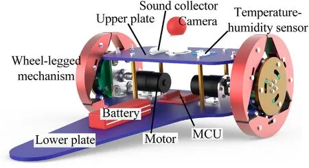
Fig.1.Virtual prototype of wheeled shape.
The reconfigurable mobile mechanism of the wheel-leg is composed of several groups of scissor type branched chain legs,each including a two-stage scissor mechanism and spokes,as shown in Fig.2.The inner disc forms a rotating pair with the outer disc,through the guide device of the outer disc.The formula M=d(n-g-1)+∑f[20] is used to calculate the degree of freedom,while the degree of freedom of each wheel-legged mechanism is 1,meaning that only the relative motion of the inner and outer discs is needed to achieve the transformation of the shape to wheel or leg.
The motions of all the branched chain legs are synchronous,while any one can be used as a trigger leg.In addition,a limiting device is set on the spokes to avoid mechanical failure and interference with other components,caused by excessive deformation.
The wheel-legged mechanism is divided into 3 branch chains and it is central symmetric.The motion of each branch chain is alike,so the motion of the whole mechanism can be obtained by analyzing only one branch chain.In the deformation mechanism,the inner disc is used as the fixed frame of reference,while point B is fixed on the inner disc.Point A is attached to the outer wheel and rotates in relation to point B,as shown in Fig.3.The motor is fixed together with the outer disc.When the robot is in the wheeled state,the motor can drive the wheel to rotate.When coming in contact with obstacles,one of the spokes will be subject to the friction from the obstacle and the ground,which will have a locking effect on this spoke.Then,the motor will continue to drive the outer disc to rotate,while the inner and outer discs will rotate in relation to each other,as the distance between point A and point B will shorten.At the same time,the two-stage scissors mechanism will open,so as to drive the spoke to expand and complete the morphological transformation.The motion of all branches is synchronous and the morphological transformation can be achieved when any one of the spokes is locked.
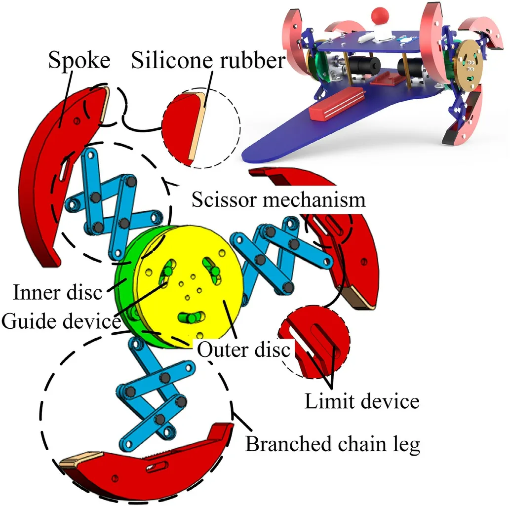
Fig.2.Wheel-legged topological mechanism.

Fig.3.Structure diagram of chain leg.
2.2.Optimization design of the branched chain leg
In the two-stage scissors mechanism,the lengths AE,BD and DH are equal and denoted as l,the distance between H and K is denoted as l,while the distance between O and B is denoted as r,as shown in Fig.3.
The coordinates system is illustrated in Fig.3,where the center of the outer disc is the origin.The connection between the center of the disc and the fixed point of the connecting rod is the X-axis and the respective vertical direction is the Y-axis.
Considering the coordinate of point K is(x,y),the spoke radius of the wheel,during the transformation process,is:

During the transformation process,the coordinates of point K can be expressed as follows:

The spoke radius of the wheel-legged mechanism,in the wheel form,is R and the folding ratio of the wheel-legged deformation mechanism is:

The longest length lthat can be accommodated in the spokes is 60 mm.After the spokes are completely closed,the distance AB,between point A and point B,is 56 mm.According to the above constraints,the length of these links is limited as follows:

Considering Eq.(3)as the objective function,all k values within the options range are compared.After the final optimization of rounding,k reaches the optimal solution value of 1.90,when the following conditions are satisfied.

3.Force analysis of wheel-legged mechanism transformation process
The process of wheel-legged shape transformation can begin,if one of the chain legs is subjected to higher friction.This chain leg is named trigger leg,while all three chain legs of the wheel-legged mechanism can be used as trigger legs.Fig.4 illustrates the force analysis of the transformation process of the wheel-legged topological mechanism.The normal contact line between spokes and obstacles is considered as the horizontal reference,while the angle between the horizontal reference line and the line between point A and the center of the disc is α.In case where the branched chain leg 1 is the trigger leg,Fig.4(a)shows that the corresponding spoke is in contact with the obstacle,but the friction force is insufficient,so the form conversion cannot initiate.Fig.4(b) shows the moment when the silicone rubber material on the trigger leg clings comes into contact with the ground,while at the same time the branch chain leg 1 bears the frictional force between the obstacle and the ground,inducing a certain locking effect on it.The inner and outer discs of the wheel-legged mechanism rotate relative to each other,thus leading to the shape conversion.
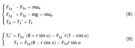
Fig.4(a) is the force schematic at the non-conversion trigger position.The force relationship can be expressed as follows:

where,r is the radius of the disc;F,F,Fand Frepresent the forces exerted by the ground and obstacles on the wheels,in the directions of X and Y,respectively;aand arepresent the acceleration of the wheel-legged mechanism in the directions of X and Y,respectively;m is the mass of the wheel.
When the wheel-legged mechanism is rotating at a constant speed,aand aare both 0 and Tcan be expressed as:

Fig.4.Stress schematics of the wheel-legged mechanism.
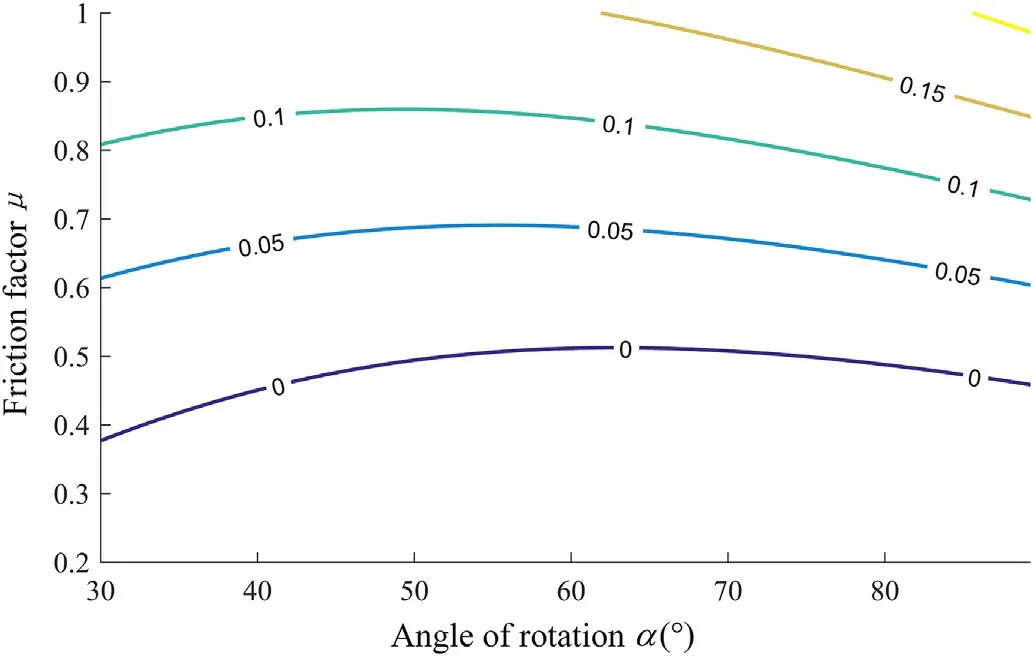
Fig.5.Theoretical value of TA in non-trigger stage.

where,μ is the friction factor between the wheel,the ground and the obstacle.
Fig.4(b) shows the force schematic at the conversion trigger position,while the following apply:
In case the wheel-legged mechanism is rotating at a constant speed,aand aare both 0 and Tcan be expressed as:


Fig.6.Theoretical value of TA in trigger stage.

Fig.7.The concept design of morphological reconfigurable walking mechanism.
The simulation analysis is carried out according to the above calculation results of torque at a constant speed.The results are shown in Figs.5-6,illustrating the simulation results at different stages.The data on the contour line is the value of torque Tin N·m.According to Figs.5-6,torque Tis proportional to friction factor μ,at each stage.Considering the robot at the position shown in Fig.3(a),μ is around 0.5 and Tis almost 0.In case μ is less than 0.5,Tis negative,so it is blocking the transformation.Therefore,in normal ground friction conditions (μ <0.5),the wheel-legged mechanism cannot deform.In case μ is around 0.8,the Tof the robot is about 0.25 N·m,at the conversion trigger position,while it is about 0.1 N·m,at the non-conversion trigger position.The torque at the trigger position is about 2.5 times its value at the nonconversion trigger position.Therefore,the tip of the branched leg is bonded with silicone rubber material,to increase the friction factor,making it possible for the inner and outer discs to rotate in relation to each other and better realize the transformation of the leg shape.The concept design of the final morphological reconfigurable walking mechanism is illustrated in Fig.7.
4.Kinematic analysis of wheel-legged mechanism
4.1.The height of climbing obstacles
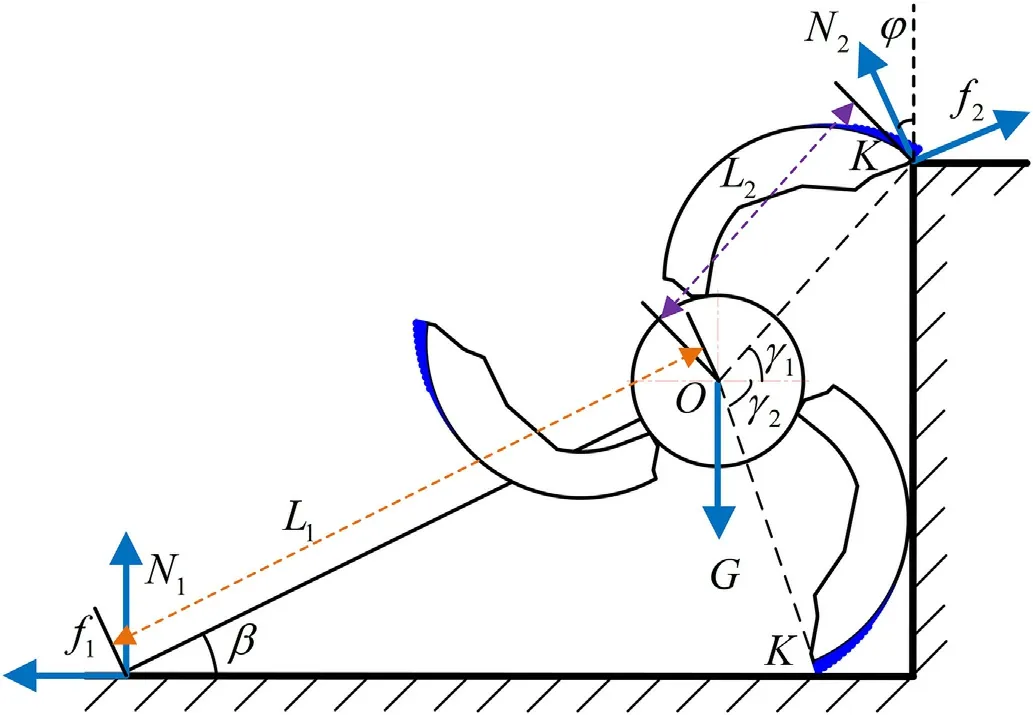
Fig.8.Stress schematic of obstacle climbing in limiting position.
The climbing obstacle height of the wheeled robot lies within a certain range.Fig.8 shows the force schematic of obstacle climbing at the limiting position.Assuming that the shape of the robot does not change during obstacle climbing,each part can be regarded as rigid.Lis the distance between the rear support point and the wheel center,while Lis the distance between the top support point and the wheel center.Nand Nare the resultant supporting forces of the two support points on the robot.The fand fare the friction forces of each point on the robot.
Just as the wheels of the robot are about to leave the ground,the obstacle height is the limiting obstacle height of the robot,while the torque to the wheel center is:

The above equation can be simplified as follows:

where,φ is the angle between Nand the vertical direction,β is the angle between Land the horizontal direction,γand γare the angle between Lin different legs and the horizontal direction.
In the above process,the required turning torque is actually the maximum value.The robot can theoretically climb the obstacles,as long as the motor can meet the torque requirement in the above process.The position illustrated in Fig.8 is the height of the limiting obstacle to be surmounted,which can be obtained as follows:

4.2.Kinematics of wheel-legged mechanism
As shown in Fig.3,in the quadrilateral OABC,the closed-loop vector equation can be expressed as:

Setting |BC|=l,|AC|=l,|OB|=l,the above equation can be projected on the axes X and Y to obtain:

Considering all of the above,Eq.(15) can be expressed as:

In Eq.(16),assuming that:

the following is derived:

According to the closed-loop vector equation,in the quadrilateral CDFE,the following relationship holds:


Considering the aforementioned relations,Eq.(20) can be expressed as:

Eq.(21) can also be expressed as:

Combining Eqs.(16) and (17),

θcan be obtained,after solving Eq.(23),as:

Next,θcan be expressed as:

Combining Eqs.(16) and (17),


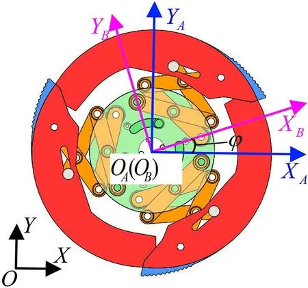
Fig.9.Coordinates systems.
The velocity of the terminal point K in the coordinates system XOYcan be obtained,following the derivative of Eq.(27) with respect to time,which can be expressed as:

Considering the derivative of Eq.(30) with respect to time,the acceleration of point K can be expressed as:
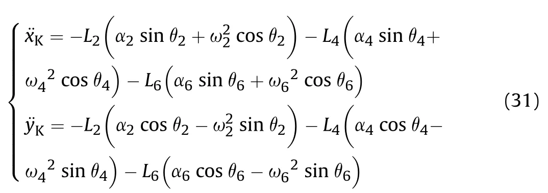
The coordinates system XOYis established at the center of the disc as the origin.During the coordinates transformation,coordinates system XOYis first converted into the Cartesian coordinates system XOYand then converted into coordinates system XOY.
As shown in Fig.9,the coordinates system XOYis marked as{A},the coordinates system XOYis marked as {B},while the world coordinates system XOY is marked as {O}.
Assuming that the angle between the coordinates system {A}and the coordinates system{B}is φ,the point K in the coordinates system {B} can be expressed as follows:

The rotation matrix of coordinates system {B} relative to coordinates system{A} can be expressed as:


Fig.10.Coordinates system motion relation.
Following,point K in the coordinates system {A} can be expressed as:

During the transformation process of the wheel-legged mechanism,the center of the disc is not stationary,but it actually shifts with the deformation.This occurs due to the increase of the radius of its own contour and the obstruction caused by the obstacles.The attempt to represent the position of frame{A}relative to frame{O}is quite complex.The model is simplified in order to describe the relative position of the two coordinates systems and facilitate the calculation.Assuming an ideal situation,where the wheel-legged mechanism encounters an obstacle and moves to the trigger position of conversion,the inner disc will not rotate,due to the obstacle,while the whole transformation process is realized by the rotation of the outer disc.
Based on the above model assumptions,when the wheel-legged mechanism just reaches the trigger position of conversion,meaning that the wheel-legged mechanism is in the wheeled shape,the coordinates of point K in the coordinates system{B}are(x,y).During the transformation process,the distance of point K changes along the axes X and Y of {B} as:

The center of the disc of the wheel-legged mechanism moves on a straight line,while the angle between the line and the X-axis of{B} is δ,which satisfies the following:

Assuming that the initial distance between{O}and{B}is s,the position relation of {A} with respect to {O} can be described as:

Next,point K in {O} can be described as:

Given point K in the world coordinates system,the velocity and acceleration in this system can be obtained by calculating the respective derivative of time.
4.3.The process of climbing obstacles
Fig.11 shows the obstacle climbing process of a mobile robot with reconfigurable wheel-legged mechanism.

c:The branched chain leg 1 serves as the trigger leg,while the motor keeps rotating,causing a relative rotation between the inner and outer discs.Wheel-legged mechanism is converted from its wheeled shape to its legged form.
d~f:The robot is at the limiting position,where the trigger leg can serve as an effective support.The branched chain leg 3 rotates until it comes into contact with the obstacle,leading the robot to successfully surmount the obstacle.
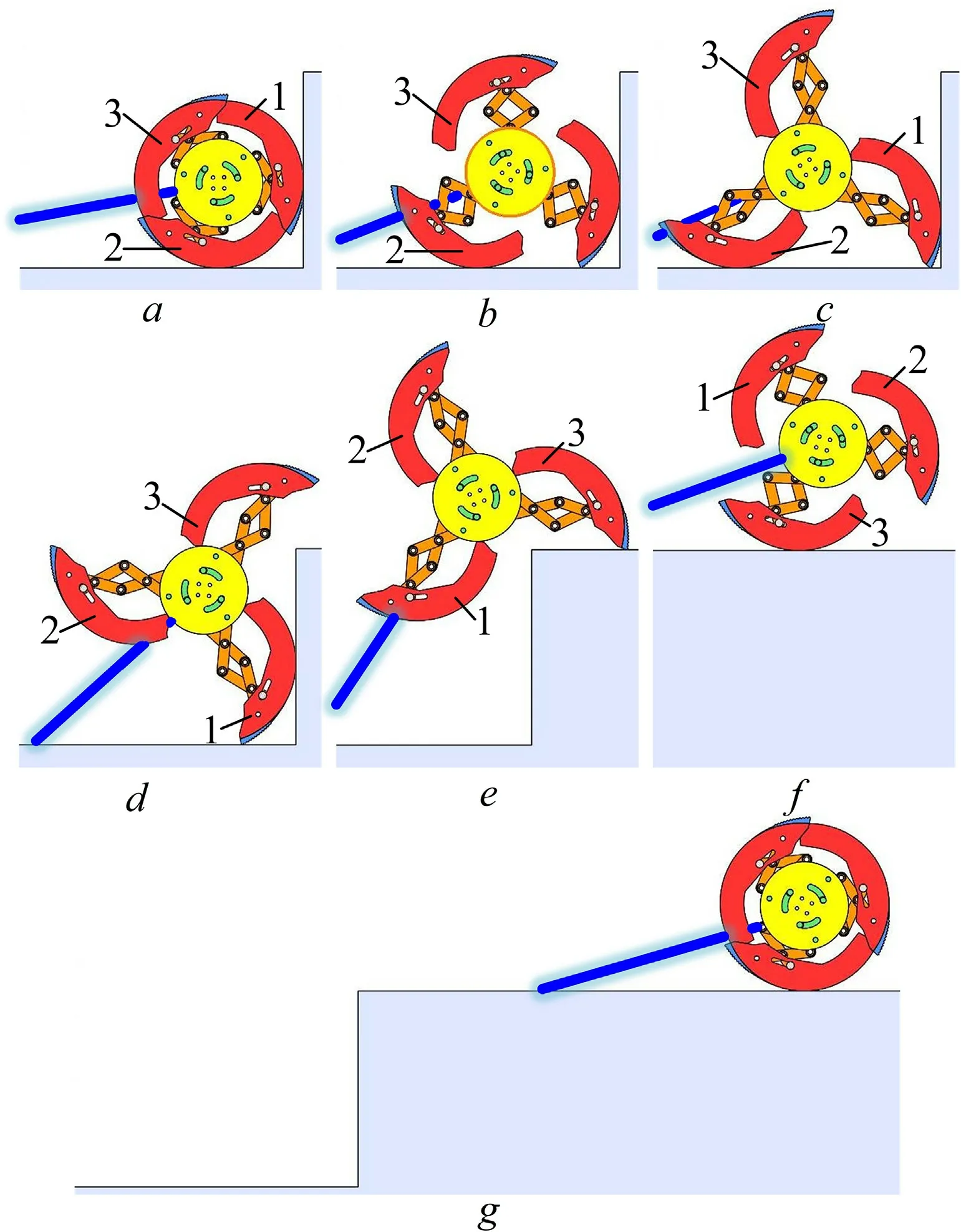
Fig.11.Obstacle surmounting process 1.

Fig.12.Obstacle surmounting process 2.
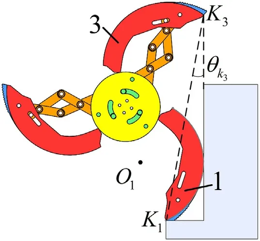
Fig.13.Schematic diagram of the minimum width of steps.
g:Following the successful surmount of the obstacle,the wheellegged mechanism transforms back from the legged shape to the wheeled shape,under the force of gravity.
Following,Fig.12 illustrates another scenario of contacting obstacles.
The tip of the branched leg 1 comes in contact with the obstacle,while the non-silicone part of the branched leg 2 is in contact with the ground.At this position,a locking effect on the spoke of branched leg 1 occurs,leading to the wheel form conversion.During the morphologic transformation process,the branched leg 2 is subject to sliding friction forces,while the nonsilicone part of the branched leg 1 begins to touch the obstacle,developing sliding friction forces in that contact region.Next,the wheel-legged mechanism converts into the state shown in Fig.11(c).

Fig.14.Schematic diagram of the continuous climbing process.
When the step is extremely narrow,the spoke of branched leg 1 comes in contact with the obstacle,which in turn causes the tip(K)of the spoke to back up along the ground.When the wheel-legged mechanism moves to the limit position as shown in Fig.13,the tip(K)of the spoke coincides with the vertical plane of the next step,and the width of the step in this case is the minimum width to allow for a foothold for the second climbing.The minimum width can be described as Eq.(39).


Next,the influence of the distance between the foothold of the current step and the vertical plane of the next step on the process of climbing obstacles will be discussed.
As shown in Fig.14,the wheel-legged mechanism rotates on a fixed axis(tip K)until the shell of spoke 1 is tangent to the ground,and then carries out pure rolling.When the tip (K) of spoke 1 comes into contact with the next step,the height of which is h,the distance between the foothold of the current step and the vertical plane of the next step is the limit width to allow the wheel-legged mechanism to climb continuously,whose solution process is shown in Eqs.(40)-(42).When the distance between the foothold of the current step and the vertical plane of the next step exceeds the limit width,the wheel-legged mechanism will intermittently climb the steps.


Fig.15.The balance control logic.

Fig.16.Clusters of linear chutes.

Fig.17.Comparison of linear chute clusters.

Table 1 Simulation parameters.

When the wheel-legged robot climbs the stairs,it generally moves perpendicular to the stairs.However,there is still a situation that the direction of motion is not perpendicular to the stairs,and the spokes of the two wheels are not opened at the same time.Thus the wheel-legged mechanism will overturn.In this paper,a motion balance control strategy is proposed,and the stability range of the center of two wheels in both horizontal and vertical directions is set to 15 mm.The detailed control logic is shown in Fig.15.
4.4.The influence of spoke linear slip and round hole on the wheellegged mechanism
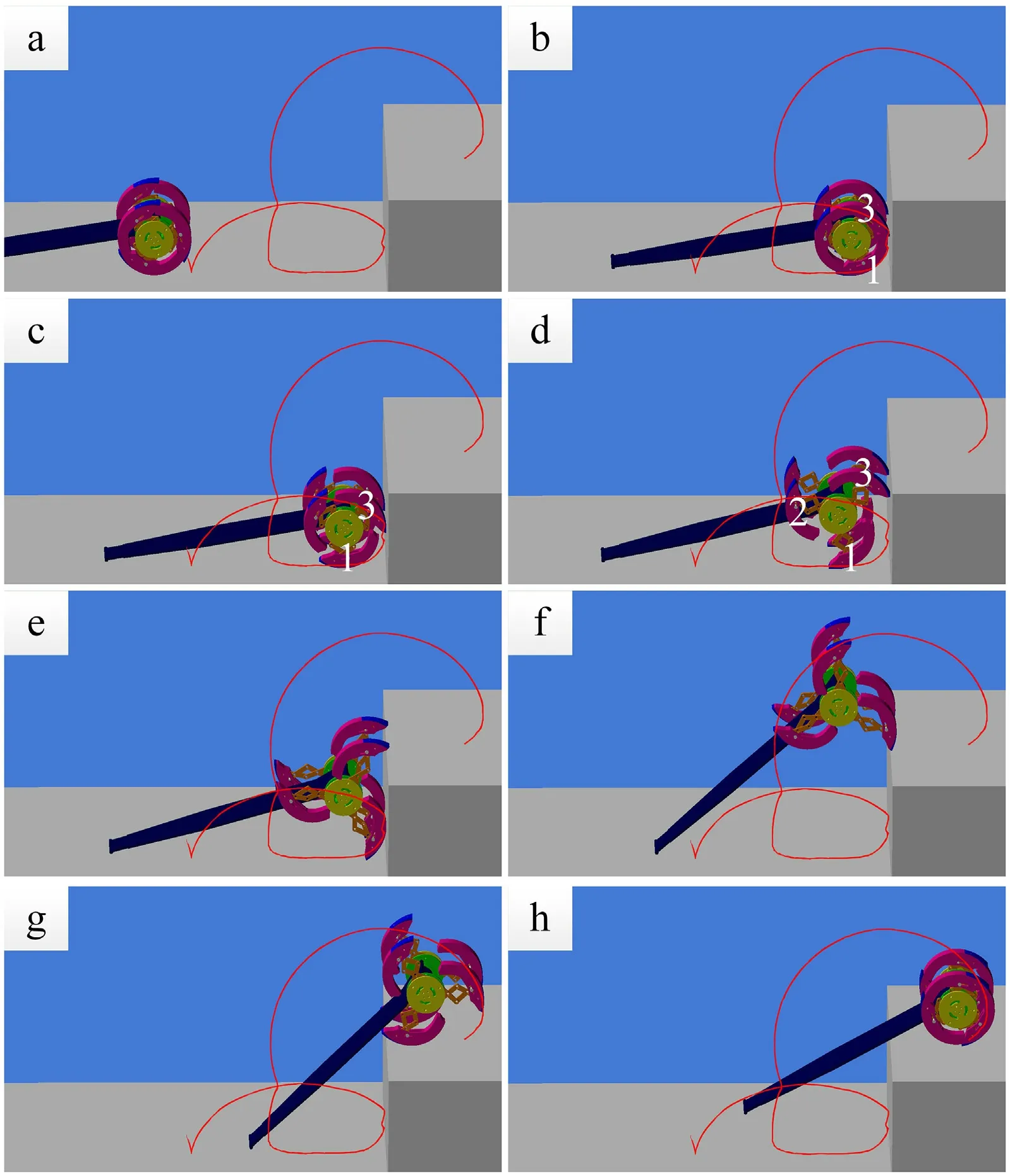
Fig.18.Climbing over the obstacles.
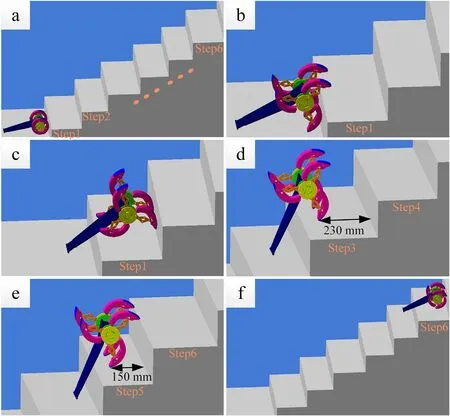
Fig.19.Climbing stairs (width:240-320 mm).
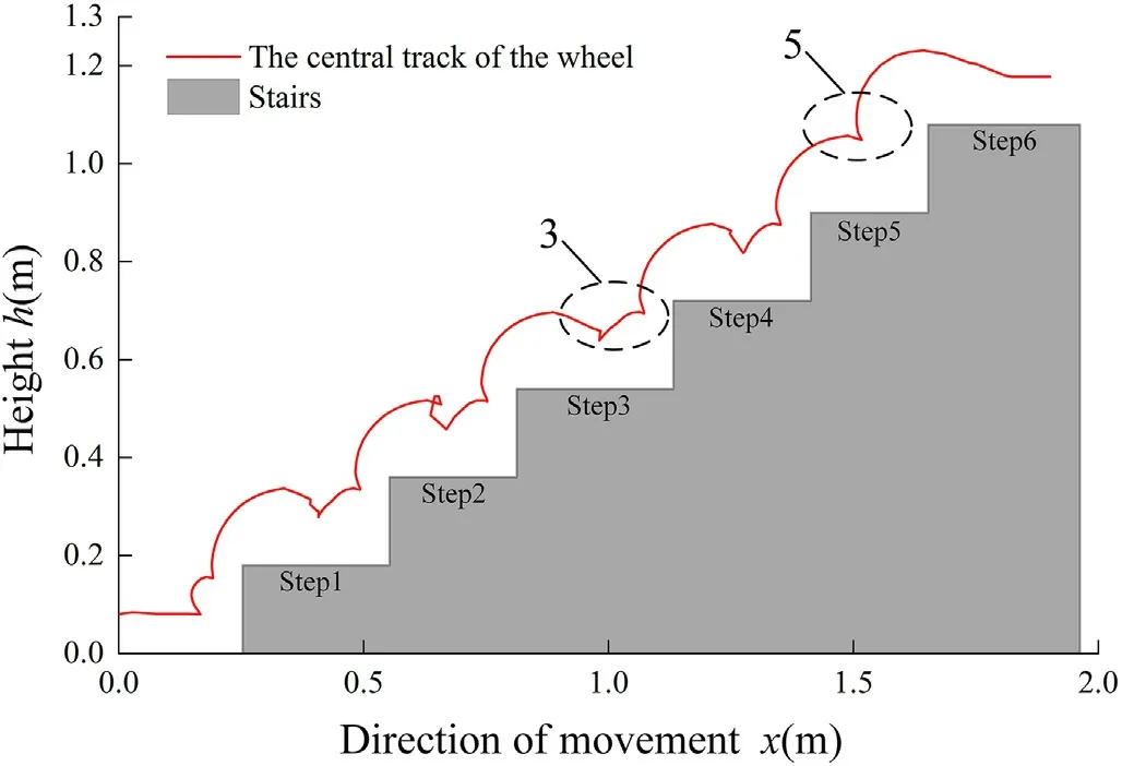
Fig.20.The trajectory of the wheel center during stairs climbing (width:240-320 mm).

If both point G and point H are designed as fixed points on the spokes,the shape conversion of the mechanism cannot achieve the desired effect.When one point is fixed,while the other is not fixed,passive motion can achieve shape conversion.In the prototype,a linear chute structure is designed,where point G is defined,while point H is considered as a fixed point.Point G moves passively in the linear chute to complete the shape conversion.
When the linear chute is at different spoke positions,as shown in Fig.16,the linear chute cluster {G2} is used to define the linear chute,without changing the position of point G,or the length of the lever EG is adjusted to shift the initial position of point G,while the linear chute cluster {G1} is used to design the linear chute.As shown in Fig.17,at different linear chute positions,the passive motion of point G varies,directly affecting the spokes motion.In the reconfiguration process of the wheel-legged mechanism,the degree of deformation differs,thus affecting the stability of the process.The position of the fixed point H determines the contour radius,after the mechanism is fully expanded,which also determines the maximum height of surmountable obstacle by the robot.

Fig.21.Climbing stairs (width:180 mm).

Fig.22.The trajectory of the wheel center during stairs climbing (width:180 mm).
5.Simulation and experimental research
The virtual prototype of the wheel-legged robot and the obstacle model were built in SolidWorks and imported into ADAMS.The initial robot and obstacle parameters are listed in Table 1.
The simulation process,as illustrated in Figs.18-26,shows that the proposed wheel-legged mobile robot design can easily climb over obstacles,stairs and gullies,at a simulation gait which is consistent with the theoretical one.
Fig.18 shows the simulation process of the robot climbing over the obstacle of the ultimate height of 269 mm.First,the branched leg 3 comes in contact with the obstacle,while the branched leg 2 is subject to sliding friction from the ground contact.Consequently,the gravity of the robot will restore the wheel-legged mechanism to its wheel shape.Leg 1 continues to remain in contact with the ground,but leg 3 leans against the obstacle.The reaction force between the obstacle and leg 3 causes the sliding friction between leg 1 and the ground,which in turn causes the robot to back up and successfully switch into the legged mobility state,but yet fails to climb the obstacle.The wheel-legged mechanism continues to convert into the leg state and successfully crosses the obstacle,the second time.The red curve in Fig.18 represents the trajectory of the branched leg 1 tip.
The simulation process of climbing stairs(width:240-320 mm,height:180 mm)and the respective generated trajectory of the disc center,during the climbing motion,are respectively shown in Figs.19 and 20.According to Eq.(42),it can be concluded that the limit width of continuous climbing is 205 mm.The distance between the foothold and the vertical plane of the next step on the third and fifth step is 230 mm and 150 mm respectively.So the wheel-legged mechanism carries out intermittent and continuous climbing on the third and fifth steps respectively,as shown in Fig.20(3,5).The simulation process of stairs climbing (width:180 mm,height:180 mm) and the respective generated trajectory of the disc center are respectively shown in Figs.21 and 22,where the distance between the foothold and the vertical plane of the next step is 96 mm.So the robot can continuously climb the stairs.After climbing the stairs,due to gravity of the robot body,it quickly returns from the legged state to the wheeled state.The trajectory of the disc center shows no obvious mutation,which proves the high stability of the mechanism while climbing over stairs and obstacles.

Fig.23.Over the gully.
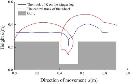
Fig.24.The track of the wheel center and K when crossing a gully.
When the robot is travelling in wheeled state,the limit width that the robot can cross is the diameter of the robot wheel shape.Next,a simulation analysis of this scenario follows.Considering the silicone material on the outside of the wheel,the width of the gully was set to 170 mm.When the wheel-legged mechanism falls into the gully,the tip of the leg 1 gets stuck on the edge,as shown in Fig.23(b).The motor then continues to rotate,with leg 1 acting as the trigger leg,while the mechanism continues to expand until leg 2 makes contact with the left side of the gully,at which point,leg 2 is locked.The reaction force between the gully and leg 2 causes the wheel leg mechanism to move forward,as shown in Fig.23(d).Next,the tip of leg 1 contacts the ground,while the robot moves forward in legged state.After climbing over the gully,the robot changes into wheeled state.The blue curve and the red curve,illustrated in Fig.24,show the track of K and the central track of the wheel,respectively,when the robot climbs the gully.
As shown in Figs.25 and 26,the balance control strategy proposed in this paper is simulated and analyzed,and it can be seen from the simulation results that the wheel-leg mechanism can automatically adjust the movement direction,and when the height difference between the two wheels exceeds the threshold,the wheel-leg mechanism can be adjusted quickly to ensure the robot to climb the steps smoothly.
Fig.27 illustrates the driving torque when climbing over an obstacle,stairs and a gully.In these conditions,the maximum driving torque of the robot is 4.7 N·m,16.7 N·m,2.5 N·m and 5.9 N·m,respectively,while the maximum torque of the selected motor is 37 N·m,which meets the requirements of the task,providing a smooth motion.
Based on the theoretical analysis and ADAMS virtual prototype simulation,the rationality of the robot design is verified and a principle prototype is developed,as shown in Fig.28.The whole prototype is mainly based on 3D printing technology using resin material.The lower plate of the robot is cut from acrylic sheet.The prototype is used to realize the basic principle of the proposal.Therefore,in order to simplify the prototype structure,the motor shafting and active triggering device are both omitted.

Fig.25.Climbing stairs when the direction of motion is not perpendicular to the stairs.
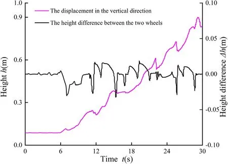
Fig.26.The simulation results when the direction of motion is not perpendicular to the stairs.
In the experiment,the angular velocity of the prototype robot was set at 15 r/min,the height of the obstacle was 250 mm,and the radius of the wheel of the prototype was 82 mm.The SBG Systems equipment was used to record data of the robot position.The experiment showed that the robot can complete the whole obstacle surmounting process,where obstacle height is about 3.05 times the spoke radius.The motion of the robot,as shown in Fig.29,includes the typical states when climbing obstacles,stairs and gully.In the experiment,the trajectory of the wheel center during obstacle and stairs climbing are shown in Figs.30-32.
The real life process of robot surmounting obstacles is consistent with the theoretical analysis.Upon contact with the obstacle,the wheel-legged mechanism is in a wheeled shape,due to insufficient friction with the ground.As the motor continues to rotate,the friction between the tip of the branched chain leg and the ground causes the wheel-legged mechanism to start deforming.Upon reaching the limiting position,the robot starts to climb over the obstacle along with the motor rotating.
In Fig.29(b) and (c),the height and width of the stairs are different.According to Eq.(42),it can be concluded that the limit width of continuous climbing is 231 mm and 245 mm in the two kinds of stairs respectively.As shown in Fig.29(b),the distance between the foothold and the vertical plane of the next step on the first and second step is 210 mm and 277 mm respectively,so the wheel-legged mechanism can climb continuously on the first step and intermittently on the second step.In Fig.29(c),the distance between the foothold and the vertical plane of the next step is 250 mm,so the wheel-legged mechanism can climb the stairs intermittently.As shown in Fig.29(d),the width of the gully was set to 170 mm.First,the wheel-legged mechanism falls into the gully,then the tip of one leg gets stuck on the edge.Next the motor continues to rotate while the mechanism continues to expand.The reaction force between the gully and leg causes the wheel-legged mechanism to move forward,and then climb over the gully successfully.After climbing over the obstacles,the gravity of the robot body restores the wheel-legged mechanism to the wheeled shape.

Fig.27.Driving torque when climbing (a) obstacle,(b)-(c) stairs and (d) gully.
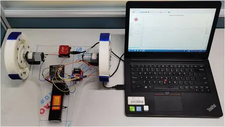
Fig.28.Principle prototype.

Fig.29.The experiment of the prototype.
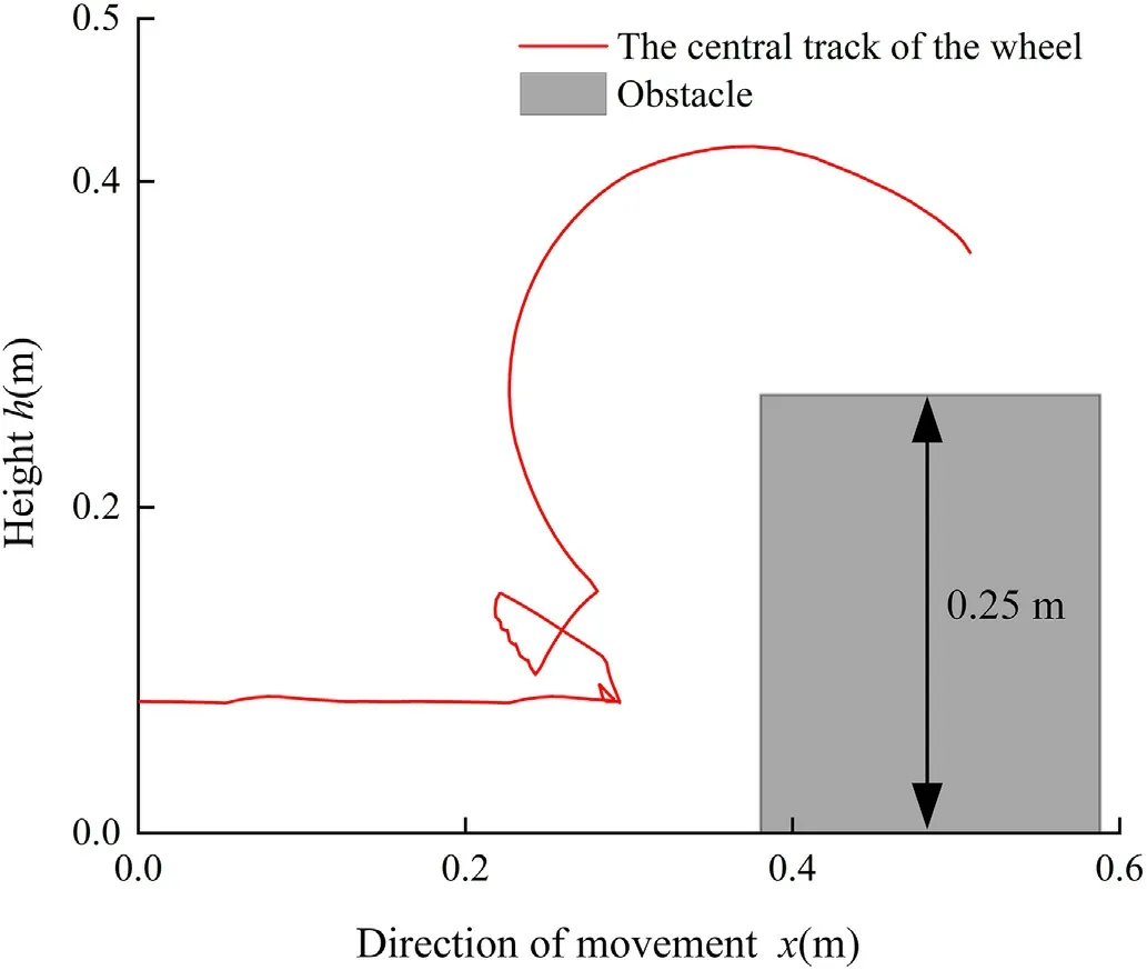
Fig.30.The trajectory of the wheel center during obstacle climbing in the experiment.

Fig.31.The trajectory of the wheel center during stairs climbing (width:280 mm) in the experiment.

Fig.32.The trajectory of the wheel center during stairs climbing (width:300 mm) in the experiment.
6.Conclusions
(1) Based on the idea of scissor mechanism and a morphological reconfigurable setup,an adaptive wheel-legged morphological reconfigurable mobile robot is innovatively designed,in this paper.Each wheel-legged mechanism is composed of multiple groups of scissor chain legs.The degree of freedom of each wheel-legged mechanism is 1,so that only the relative motion of the inner and outer discs is needed to achieve the conversion of the shape from wheeled into legged and vice versa.
(2) Force analysis shows that the torque Tis proportional to the friction factor μ,during the conversion from wheeled shape into legged shape.By increasing the friction factor of the branched chain leg tip,the inner and outer discs are more likely to rotate relative to each other.
(3) From the perspective of kinematics,the performance of the robot in climbing obstacles,stairs and gullies was analyzed,deriving the folding ratio and maximum obstacle height for the wheel-legged deformation mechanism.
(4) ADAMS simulation and prototype experiments showed that,the robot can easily climb over obstacles,stairs and gullies.The maximum height of obstacle is about 3.05 times the spokes radius.Experiments showed that the mechanism is of considerable stability and practicability.
The authors declare that they have no known competing financial interests or personal relationships that could have appeared to influence the work reported in this paper.
This study was financially supported by the National Key R&D Program of China (No.2017YFE0112200),Hebei Province Science and Technology Support Program (No.19391825D) and Postgraduate Innovation Subsidy Project of Hebei Province (No.CXZZBS2021134).
杂志排行
Defence Technology的其它文章
- Effect of porosity on active damping of geometrically nonlinear vibrations of a functionally graded magneto-electro-elastic plate
- Theoretical predict structure and property of the novel CL-20/2,4-DNI cocrystal by systematic search approach
- Effect of different geometrical non-uniformities on nonlinear vibration of porous functionally graded skew plates:A finite element study
- Manipulator-based autonomous inspections at road checkpoints:Application of faster YOLO for detecting large objects
- Penetration and internal blast behavior of reactive liner enhanced shaped charge against concrete space
- Failure investigation on high velocity impact deformation of boron carbide(B4C)reinforced fiber metal laminates of titanium/glass fiber reinforced polymer
