Effect of the micro vortex generator on the characteristics of vaporized RP-3 kerosene combustion in supersonic flows
2022-05-24DongpengJIAKaiYANGYuPANXipengLINingWANG
Dong-peng JIA,Kai YANG,Yu PAN,Xi-peng LI,Ning WANG
Science and Technology on Scramjet Laboratory,College of Aerospace Science and Engineering,National University of Defense Technology,Changsha 410073,China
Abstract: To investigate the characteristics of vaporized RP-3 kerosene combustion in a scramjet combustor enhanced by the micro vortex generator (MVG),a series of experiments are carried out based on the advanced combustion diagnosis technique.The high-enthalpy incoming flow is accelerated to supersonic through a Mach 2.52 nozzle,the total pressure and temperature of which are 1.6 MPa and 1486 K,respectively.The effect of MVG on the ignition process,flame distribution,and combustor pressure along the bottom wall is well revealed,and the effects of the position and number of MVGs on stable combustion performance are analyzed.The results indicate that the development processes of the initial flame kernel with and without an MVG during ignition process show a similar behavior.The installation of an MVG can lift the shear layer,promote the penetration of flame deeper into the mainstream,and expand the area of the reactive region.Reducing the distance between the MVG and the injection position and increasing the number of MVGs are regarded as effective ways of improving the mixing degree of fuel and air with a resultant intensification of chemical reactions and flame luminescence.The effect of mixing and subsequent combustion is enhanced by shortening the distance between the MVG and the injection position.As the layout schemes of the MVG vary,the pressure distribution between the injection position and the leading edge of the cavity changes considerably,while that in the cavity remains almost constant.Increasing the number of MVGs is also beneficial for improving the premixed degree of fuel and incoming flow and results in more violent chemical reactions downstream of the cavity.
Key words:Vaporized RP-3 kerosene;Micro vortex generator(MVG);Ignition process;Cavity-stabilized flame
1 Introduction
Achieving reliable ignition and high-efficiency combustion in supersonic flow is a primary challenge due to the intense turbulence and high-speed incoming flow,and affects the application of supersonic com‐bustion chambers in hypersonic vehicles (Ben-Yakar and Hanson,2001;Neill and Pesyridis,2017;Urzay,2018).Due to its relatively high volumetric energy density and low cost,aviation kerosene is extensively used as fuel for scramjet engines.In addition,as a kind of endothermic hydrocarbon fuel,kerosene can absorb a large amount of heat in regenerative cooling channels,which is particularly important for solv‐ing the thermal protection problem of the engines(Ning et al.,2013;Ferraiuolo et al.,2017).More im‐portantly,the kerosene in the cooling channel is in the supercritical state after absorbing heat,which elimi‐nates the atomization and evaporation of the liquid kerosene in the combustor(Vincent-Randonnier et al.,2008),improves the mixing effects (Fan et al.,2006),and reduces the ignition delay time (Ravindran et al.,2019).
Although the use of vaporized kerosene brings many benefits for improving the mixing effects,obtain‐ing high-efficiency and steady combustion is not easy.To increase the combustion efficiency,current scram‐jets commonly adopt various flame holders such as struts(Li et al.,2020a;Liu XL et al.,2020;Qiu et al.,2020;Zhang JL et al.,2020),backward facing steps(Baigmohammadi et al.,2019;Pillai et al.,2020;Zhang JC et al.,2020) and cavities (Kummitha et al.,2018a;Choubey et al.,2019;Jeong et al.,2020).As a nonintrusive method,cavity flame holders have been widely used in supersonic combustors due to their outstanding potential to stabilize combustion without excessive total pressure loss.
Although the geometric structure of the cavity flame holder is quite simple,the combustion mecha‐nism involved is complicated.Many studies have been carried out on cavity flame holders (Tuncer,2010;Liu CY et al.,2017,2020;Li et al.,2020b).Le et al.(2012)studied the combustion characteristics of kero‐sene injected upstream of a cavity flame holder in a Mach 2.6 flow.They observed two stabilization re‐gimes of the cavity flame,the shear-layer-stabilized flame and the recirculation-zone-stabilized flame.Shi et al.(2017) experimentally and numerically studied the influence of cavity configurations with aspect ratios of 9 and 11 on the flame-holding and perfor‐mance of a kerosene fuelled scramjet combustor.The results showed that the burner with a downstream cav‐ity aspect ratio of 9 had a higher combustion efficiency and pressure recovery ratios.Zhang and Song (2017)investigated the liquid kerosene ignition and flameholding characteristics of three types of flame holders in a circular supersonic combustion chamber.They found that the cavity flame holder could achieve igni‐tion and flame-holding within a narrow equivalence ratio range.Bao et al.(2015) studied the influence of the cavity aspect ratio on the ignition of liquid kero‐sene under Mach 4.5 flight conditions.The results in‐dicated that the local flame strength of the cavity with a smallerL
/D
(length to depth ratio) was too weak,which made igniting the fuel in the main flow difficult.The cavity with a largerL
/D
had a better ignition per‐formance.The angle of jets also has a significant ef‐fect on the mixing efficiency.Kummitha et al.(2018b)noted that the combination of direct and passive fuel injection technology could improve the mixing and combustion efficiency.Jeong et al.(2020) investigated the influence of the fuel injection position on super‐sonic hydrogen combustion.They found that upstream injection enhanced fuel diffusion and enabled igni‐tion with a shorter delay time.Yang et al.(2020)stud‐ied the influence of the fuel temperature on the ignition performance under lean fuel conditions in a Mach 2.52 scramjet combustor and analyzed the ignition failure mechanism as the fuel temperature increased.The above-mentioned methods aimed to change the cavity configurations and fuel injection strategies to achieve better mixing and combustion performance.The micro vortex generator (MVG) may also realize these purposes to some extent (Huang et al.,2019,2020).It was found that the delta wing vortex genera‐tor could improve mixing efficiency and fuel penetra‐tion depth (Li et al.,2017a,2017b).Saravanan and Suresh(2012)found that the MVG could improve the fuel/air mixing effect and the performance of the com‐bustor.Aguilera and Yu(2015,2017)found that by re‐ducing the intensity of shock waves caused by jets,fins could enhance fuel/air mixing by increasing pene‐tration and spreading.In the performance study of a solid scramjet,Li et al.(2019) also observed that the vortex generators could significantly promote mixing and stable combustion.
The effectiveness of MVG in enhancing the fuel/air mixing effect has been demonstrated in various ways.However,this method has not been fully evalu‐ated in a cavity-based supersonic combustor,especially a combustor where vaporized kerosene is used as the fuel.In this paper,MVGs are installed downstream of the injection position and upstream of the cavity to evaluate the mixing effect of the incoming flow and fuel.This paper mainly investigates the effect of MVG on the combustion characteristics of vaporized RP-3 kerosene,with the aim of better understanding the role of the position and quantity of MVG in a supersonic combustor.
2 Experimental apparatus
2.1 Test facility
A direct-connected test device with a mass flow rate of 1 kg/s is used to perform the experiments in this study.By burning alcohol,oxygen,and air in the air heater,a high-enthalpy gas with a total pressure of 1.6 MPa and a total temperature of 1486 K can be produced.The gas produced by the air heater with an oxygen mole fraction of 21% passes through a 2D Laval nozzle of Mach 2.52,and can be accelerated to a supersonic state to simulate the entrance flow of the scramjet combustor.The parameters of the entrance flow correspond to the flight conditions of Mach 5.5 at an altitude of 25 km.
2.2 Heating system of RP-3 kerosene
In this paper,the common China RP-3 aviation kerosene is used as the fuel.Heating the kerosene to a vaporized state and injecting it into the combustor at a high temperature and pressure is not easy.To solve this problem,our research group specially designed a heating system to produce vaporized kerosene.That system has been described in detail in previous re‐search(Yang et al.,2020).
A high-pressure nitrogen gas source is used to in‐crease the pressure of kerosene in the storage tank and a customized two-stage electric heating system is used to heat the kerosene.The maximum output volt‐age and maximum output current of the first-stage heating system are 136 V and 440 A,respectively,and are mainly used to heat the kerosene in the stainlesssteel pipe.A heating cable with a maximum output power of 700 W wraps the downstream pipe as the secondary heating system to preheat the downstream pipe and further heat the kerosene.
2.3 Supersonic combustor
The configuration of the supersonic combustor is shown in Fig.1.

Fig.1 Sketch of the supersonic combustor.The explanations of Loc1,Loc2,and Loc3 are given in Section 2.4
The length,height,and width of the cross section of the supersonic combustor are 541,40,and 50 mm,respectively.The top and bottom walls of the super‐sonic combustor are both horizontal.The tail of the bottom wall in the combustor is a special arc section that connects to the expansion section.The expansion section with a length of 245 mm diverges at an angle of 3.1°.A cavity flame stabilizer with a depth of 15 mm is installed on the bottom wall of the combustor.The length to width ratio of the cavity is 7,and its rear part is a 45° ramp.The leading edge of the cavity is perpendicular to the bottom wall of the combustor,and the distance from the combustor inlet is 289 mm.A spark plug with an energy storage capacity of 5 J and a frequency of 50 Hz for pulse-discharge ignition is installed at the center of the bottom of the cavity.
The heated fuel is injected transversely through a hole injector with a diameter of 1.0 mm along the center line of the bottom wall into the incoming flow.The fuel injection position is 180 mm from the lead‐ing edge of the downstream cavity.
2.4 Micro vortex generator
Two kinds of MVG with different sizes are used.Fig.2 shows the larger size MVG with a length of 14.11 mm,a width of 16.30 mm,and a height of 3.00 mm.Due to the limitation of the width of the com‑bustion chamber,four of these MVGs cannot be arran‑ged in the width direction at the same time so,when studying the influence of four MVGs,a smaller MVG is used.The smaller MVG has a width of 7.56 mm,but its length and height are consistent with those of the larger MVGs.
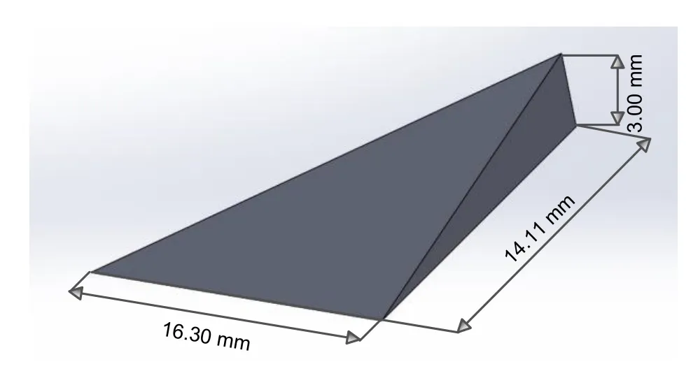
Fig.2 Dimensions of the larger micro vortex generator
The MVGs are installed downstream of the fuel injection position and upstream of the cavity.Detailed information on the installation locations is shown in Fig.3.
As shown in Fig.3a,when only one MVG is in‐stalled,the MVG is arranged at three positions.These three positions are 120,70,and 20 mm from the front edge of the downstream cavity and these layout schemes are named Loc1,Loc2,and Loc3,respec‐tively.When multiple MVGs are arranged at the same time,the arrangement position is not on the center line of the bottom wall.This paper also studies the in‐fluence of the number of MVGs on the ignition char‐acteristics.Two or four identical MVGs are arranged 20 mm from the front edge of the cavity.The specific layout positions are shown in Figs.3b and 3c,and these two layout schemes are called Loc3-2 and Loc3-4.The distances between two adjacent MVGs in Loc3-2 and Loc3-4 are 25 and 10 mm,respectively.
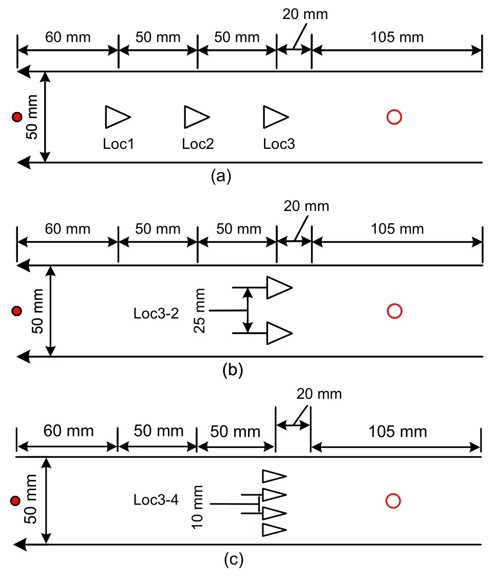
Fig.3 Top view of layout schemes of the micro vortex generators:(a) one micro vortex generator;(b) two micro vortex generators;(c)four micro vortex generators
2.5 Image and data acquisition
A high-speed camera (Photron FASTCAM SAX2,Japan)is used to directly record the glowing image of the flame in the combustor.The frame rate,exposure time,and spatial resolution of the captured image are 20 kHz,40 μs,and 0.167 mm/pixel,respectively.
The temperature of the fuel before injection is measured by a K-type armoured thermocouple with a wire diameter of 0.5 mm.The measurement range of the thermocouple is up to 1200°C,and its accuracy is±0.75%.The fuel injection pressure is measured by a pressure sensor with a range of 0–10 MPa.The mea‐surement frequency of the pressure sensor is 20 kHz,and the measurement error is within ±0.1%.To better monitor the pressure distribution in the combustor during ignition and combustion,pressure measuring holes with diameters of 0.5 mm are arranged on the center lines of the bottom wall and the top wall of the combustor.Pressure scanners are used to measure the pressure on the top and bottom walls with a sampling frequency of 100 Hz.Each pressure scanner includes 16 measurement channels with a measurement range of 0–100 psi (1 MPa=145 psi) and an uncertainty of 0.05%.
3 Results and discussion
3.1 Ignition characteristics with and without a micro vortex generator
To avoid the influence of other parameters on the ignition and combustion process,the supply pres‐sure of the heating system for the vaporized kerosene is controlled at 2.4 MPa during the experiment.How‐ever,the actual injection pressure,fuel temperature,and mass flow rates in the experiment inevitably drift slightly,but all within acceptable limits.Table 1 shows the specific operating conditions of the injec‐tion system.The experimental condition without an MVG is called the flat scheme.The MVG is in‐stalled 120 mm downstream of the injection position in the Loc3 scheme.
All the experiments are performed in relatively low light to reduce the impact of natural light on im‐age acquisition.As shown in Fig.4,we select several typical images to examine the effect of an MVG on the development process of the initial flame kernel during the ignition process.Images of the ignition pro‐cess without and with an MVG are shown in Figs.4a and 4b,respectively.Because a spark plug is adopted as the ignition equipment,images during initial ignition are inevitably affected by the spark plug light and appear too bright.
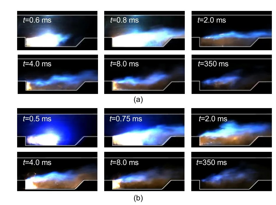
Fig.4 Ignition progress of the combustor:(a) without a micro vortex generator;(b)with a micro vortex generator at Loc3
The development processes of the initial flame kernel in the two conditions are similar.After the first discharge of the spark plug,an initial flame is formed on the bottom wall of the cavity near the spark plug.Due to the effect of circulation flow in the cavity,the flame gradually moves upstream to the leading edge of the cavity.The flame develops into a relatively stable flame at the leading edge of the cavity.The pro‐cess of flame propagation and development upstream occupies most of the time of formation of the entire cavity flame.Then,the leading-edge flame propa‐gates downstream to fill the whole cavity,spreading so quickly that this process occupies less time.Even‐tually,the cavity-stabilized flame concentrates on the shear layer and the cavity ramp.
Although the ignition processes with and with‐out an MVG are similar,some obvious differences can still be observed between their flame shapes by com‐paring the last three images of the ignition processes.On the one hand,the initial flame can penetrate the shear layer into the mainstream while propagating downstream along the shear layer.The flame in the mainstream area with an MVG is more vigorous than that without one.On the other hand,the flame intensity is also stronger with an MVG.This phenomenon sug‐gests that the installation of an MVG can enhance the mixing of the incoming flow and vaporized kerosene to some extent.The full mixing effect is beneficial to the chemical reaction.An enhanced chemical reac‐tion may increase the local pressure in the combustor.The local high pressure induced by chemical heat release with an MVG can lift the shear layer and promote penetration of the flame region deeper into the mainstream.
To better describe the cavity-stabilized flame dis‐tribution during stable combustion and further support the conclusion mentioned above,the time-averaged images after simple processing are given in Fig.5.The time-averaged images are averaged over 1008 consecutive images taken by the high-speed camera during stable combustion.In addition,we add a white outline to the flame boundary for clear identification.The flame area in Fig.5b is larger than that in Fig.5a.To quantitatively describe the flame range,the height of the upper boundary of the flame(H
)to the bottom wall of the combustor in cavity is given in Fig.6.The leading edge is the origin of theX
direction.It can also be found that the upper boundary of the flame for Loc3 is taller than that for flat.The comparison of flame profiles indicates that the MVG can expand the area of the flame region.The image of the time-averaged flame during stable combustion also confirms that the installation of an MVG is beneficial to the flame pen‐etrating deeper into the mainstream.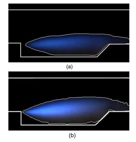
Fig.5 Profiles of the cavity-stabilized flame:(a)without a micro vortex generator;(b)with a micro vortex generator at Loc3
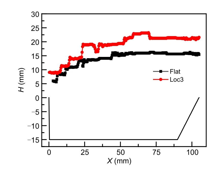
Fig.6 Comparison of the flame distribution without and with a micro vortex generator at Loc3
In summary,by comparing the images of the ignition process and the time-averaged flame profile,it can be concluded that the local high pressure in‐duced by chemical heat release with an MVG lifts the shear layer and promotes penetration of the flame region deeper into the mainstream.The pressure distribution on the bottom wall of the combustor in these two cases further confirms this conclusion(Fig.7).
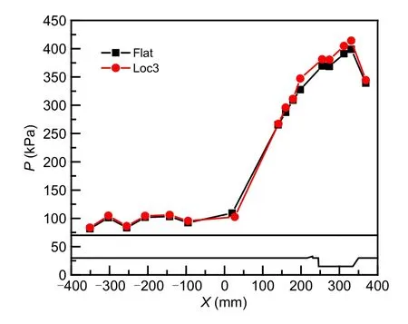
Fig.7 Comparison of the pressure (P) distribution without and with a micro vortex generator at Loc3
3.2 Effect of the position and number of micro vortex generators
In the last section,we have examined the effect of an MVG on the ignition process and stable com‐bustion.The effect of an MVG on ignition and com‐bustion is mainly realized by changing the mixing of the fuel and supersonic incoming flow.The layout scheme of the MVG determines the flow field struc‐ture of the entire combustion chamber.The position and number of the MVGs play an important role in the mixing effect of the incoming flow and vaporized kerosene.In addition to the placement of an MVG at Loc3,we also arrange a single MVG at two other locations to investigate the characteristics of ignition and combustion.Subsequently,experiments with two and four MVGs installed at Loc3 are carried out.The specific operating conditions are listed in Table 2.The images obtained by the high-speed camera indicate that the changes in the position and quantity of the MVG do not affect the development of the initial flame kernel.The flame development process does not need to be repeated because all the initial flames follow a similar development rule.In this section,we mainly focus on the characteristics of flame during stable combustion.
The pseudo-color images of the cavity-stabilized flame with a single MVG at various positions are shown in Fig.8.First,we choose the same processing method as above to obtain the time-averaged image for each experimental condition.To improve the discern‐ibility of the cavity-stabilized flames,we perform the same pseudo-color enhancement on the time-averaged images.The region of the cavity-stabilized flame grad‐ually decreases as the position of the MVG moves downstream.Moreover,the brightness of the cavitystabilized flame gradually fades with the downstream movement of the MVG,especially in the central area of the flame (corresponding to the red area in each image).The vortex structure around the MVG can ef‐fectively influence the interaction between the incom‐ing flow and fuel and then affect the flow field of the entire combustor.When the MVG is close to the injec‐tion position,the separation of the turbulence boundary layer induced by it is very close to the fuel jet,which may affect the mixing effect to some extent.The mixing effect of the incoming flow and vaporized ker‐osene is weakened as the distance between the injec‐tion position and MVG increases.This explains why the combustion intensity decreases as the MVG moves downstream.

Fig.8 Pseudo-color images of the cavity-stabilized flame with a micro vortex generator at various positions.References to color refer to the online version of this figure
To some extent,the intensity of the chemical re‐action during stable combustion can be characterized by the light intensity of the flame.To quantitatively de‐scribe the changing trend of flame brightness with the position of the MVG,we also calculate the average light intensity of 1008 consecutive cavity-stabilized images of the flame under each condition.The value is normalized by the time-averaged light intensity at Loc3.Table 3 presents the time-averaged light intensity of stabilized flame images under various layout sche‑mes after normalization.It can be found that decreas‐ing distance between the injection position and MVG increases the light intensity by 15.6%.When the MVG is closer to the injection,the vortex structure generated by the separation of the boundary layer can quickly af‐fect the mixing of the incoming flow and fuel,which is beneficial to improve mixing efficiency.When the MVG is far away from the injection,the vortex may diffuse around it,resulting in a gradual decrease in the intensity of turbulence on the centerline.However,the fuel is mainly distributed in the center of the combus‐tor rather than at the side walls.Therefore,when the MVG is closer to the injection position,the mixing degree of the fuel and incoming flow is better.The greater degree of mixing improves the resultant inten‐sity of chemical reactions and the flame luminescence.
Fig.9 illustrates the comparison of the pressure distributions on the bottom wall of the combustor for the MVG at different positions.The injection position is located atX
=65 mm.Because the position of the MVG has little effect on the pressure upstream of the injection position,in order to show more clearly that the pressure distribution varies along the vortex generator,only the pressure in the range ofX
>0 mm is displayed in the diagram.The pressure distribution along theX
direction is consistent under the three layout schemes.When the MVG is installed at different positions,the pressure in the range ofX
=84–331 mm is significantly different.For each measurement position of the pres‐sure on the bottom wall of the combustor,the pressure decreases as the MVG moves downstream,especially between the injection position and the leading edge of the cavity.Although the pressure distribution in the cavity shows a uniform trend,the difference is rela‐tively small.In summary,the position of the MVG mainly affects the wall pressure between the injection position and cavity while having little effect in the cavity itself.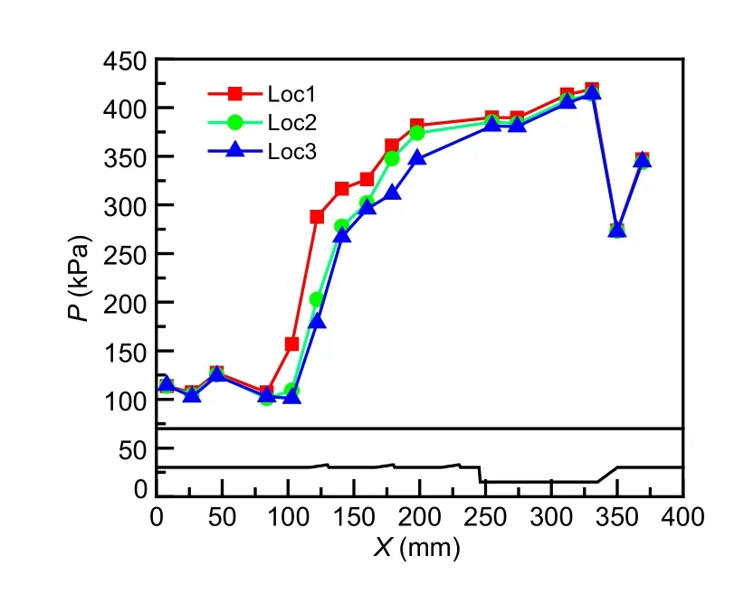
Fig.9 Comparison of the pressure distributions of the combustor with the micro vortex generator at different positions
Fig.10 shows pseudo-color images of the cavity flame with different numbers of MVG at the same po‐sition.The average brightness of the cavity-stabilized flame intensifies as the number of MVGs increases from one to two.By comparing the red area and the whole area of the cavity-stabilized flame,the shear layer can also be found to be lifted slightly higher.Compared with a single MVG,two MVGs are also beneficial for improving the premixed degree of fuel and air before combustion,resulting in more violent chemical reactions in the downstream region.The time-averaged light intensity of the stabilized flame images in Table 3 also confirms the result that increas‐ing the number of MVGs promotes chemical reac‐tions.The time-averaged light intensity with two and four MVGs is 10.8%and 11.3%higher than that with a single MVG,respectively.Pseudo-color images and the time-averaged light intensity all indicate that no obvious differences occur between the images of the cavity-stabilized flames with two or four MVGs.This phenomenon may be due to the width of each MVG in layout Loc3-4 being only approximately half that in layout Loc3-2.In addition,the length and height of each MVG in Loc3-2 and Loc3-4 are identical.There‐fore,the influence of the vortex generated by the two MVGs and the four MVGs on the mixing effect may show obvious difference.The effect of the number of MVGs on the combustion characteristics still needs further study.

Fig.10 Pseudo-color images of the cavity-stabilized flame with different numbers of micro vortex generators at the same position.References to color refer to the online version of this figure
Fig.11 gives a comparison of the pressure distri‐butions on the bottom wall of the combustor with var‐ious numbers of MVGs.As the number of MVGs in‐creases from one to two,the pressure downstream of the injection position and upstream of the cavity sig‐nificantly increases.The pressure distribution shows almost no change as the number of MVGs is increased to four.The increase in the number of MVGs can in‐deed be considered to improve the premixed degree of fuel and air before combustion,resulting in more violent chemical reactions in the downstream region.However,the effect of further increasing the number of MVGs on the combustion performance is extremely weak.We have analyzed the reasons for this result.In addition,by comparing the effects of changing the po‐sition and number of MVGs on the cavity-stabilized flame,we can conclude that the position of the MVGs may play a more important role in the combustion per‐formance than their number.
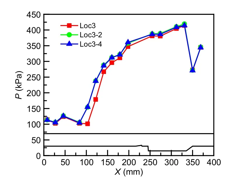
Fig.11 Comparison of the pressure distributions on the bottom wall of the combustor with various numbers of micro vortex generators
4 Conclusions
The combustion characteristics of vaporized RP-3 kerosene with MVGs in supersonic flows simulated under Mach 5.5 flight conditions are experimentally investigated in this paper.MVGs are installed on the bottom wall,downstream of the injection position,and upstream of the cavity.By comparing the flame images of the ignition process and the cavity-stabilized flame under various layout schemes of MVG,some signifi‐cant conclusions can be drawn:
1.Though the ignition processes with and with‐out an MVG show a similar tendency,an MVG can effectively improve the combustion intensity after stable combustion has been achieved.The local high pressure induced by chemical heat release with the MVG can lift the shear layer and promote the penetra‐tion of the flame region deeper into the mainstream.
2.By shortening the distance between the MVG and the injection position,the interaction between in‐coming flow and fuel jet is enhanced,facilitating the mixing effect and subsequent combustion.The light intensity can be increased by 15.6%by decreasing the distance between the injection position and the MVG in this paper.The position of the MVG mainly affects the pressure between the injection position and the cavity,but has a little effect on the cavity itself.
3.An increase in the number of MVGs is also beneficial in improving the premixed degree of fuel and air before combustion,as it results in more vio‐lent chemical reactions in the downstream region.However,the position of the MVGs may play a more important role in the combustion performance.
Acknowledgments
This work is supported by the National Natural Science Foundation of China(No.12002373).
Author contributions
Dong-peng JIA designed the research.Dong-peng JIA,Yu PAN,and Ning WANG processed the corresponding data.Dong-peng JIA wrote the first draft of the manuscript.Kai YANG helped to organize the manuscript.Xi-peng LI revised and edited the final version.
Conflict of interest
Dong-peng JIA,Kai YANG,Yu PAN,Xi-peng LI,and Ning WANG declare that they have no conflict of interest.
杂志排行
Journal of Zhejiang University-Science A(Applied Physics & Engineering)的其它文章
- Recycling Bayer and sintering red muds in brick production:a review
- An analytical investigation of the collapse of asymmetrically corroded pipes under external pressure
- Vertical temperature gradients of concrete box girder caused by solar radiation in Sichuan-Tibet railway
- Numerical study on ethylene-air continuous rotating detonation in annular combustors with different widths
- Influence of momentum ratio control mode on spray and combustion characteristics of a LOX/LCH4 pintle injector
