Development and application of a multi-physics and multi-scale coupling program for lead-cooled fast reactor
2022-05-13XiaoLuoChiWangZeRenZouLianKaiCaoShuaiWangZhaoChenHongLiChen
Xiao Luo · Chi Wang · Ze-Ren Zou · Lian-Kai Cao · Shuai Wang ·Zhao Chen · Hong-Li Chen
Abstract In this study, a multi-physics and multi-scale coupling program, Fluent/KMC-sub/NDK, was developed based on the user-defined functions (UDF) of Fluent, in which the KMC-sub-code is a sub-channel thermal-hydraulic code and the NDK code is a neutron diffusion code.The coupling program framework adopts the ‘‘masterslave’’ mode, in which Fluent is the master program while NDK and KMC-sub are coupled internally and compiled into the dynamic link library (DLL) as slave codes. The domain decomposition method was adopted, in which the reactor core was simulated by NDK and KMC-sub, while the rest of the primary loop was simulated using Fluent.A simulation of the reactor shutdown process of M2LFR-1000 was carried out using the coupling program, and the code-to-code verification was performed with ATHLET,demonstrating a good agreement, with absolute deviation was smaller than 0.2%. The results show an obvious thermal stratification phenomenon during the shutdown process,which occurs 10 s after shutdown,and the change in thermal stratification phenomena is also captured by the coupling program. At the same time, the change in the neutron flux density distribution of the reactor was also obtained.
Keywords Multi-physics and multi-scale coupling method · User-defined functions · Dynamic link library ·Thermal stratification · Lead-cooled fast reactor
1 Introduction
Safety analysis is a key tool for proving the safety of nuclear power plants during the design phase. Usually, the safety analysis of nuclear power plants is carried out using a system analysis code, which adopts the one-dimensional approximate simplification method to model the real plant system. However, there is three-dimensional flow and thermal stratification in the pool structure of lead-cooled fast reactors(LFRs),which cannot be simulated by system codes, especially in the accident state. On the other hand,CFD tools such as Fluent can capture the complex threedimensional flow and heat transfer phenomenon in detail,which can carry out accurate numerical simulation analysis of the plenum in LFRs. However, they may require very large computational effort to simulate such important phenomena.
In this case, a multi-scale coupling method is proposed to meet this demand.Aumille et al.proposed a RELAP-3D/CFD coupling methodology and performed a proof-ofprinciple calculation based on the coupling code [1, 2].Unlike the explicit CFD coupling method, this coupling method is numerically stable,provided the Courant limit is not violated in RELAP5-3D or at the coupling locations.Gesellschaft fu¨r Anlagen- und Reaktorsicherheit (GRS)proposed an explicit coupling method and developed a 1D system/3D-CFD coupling program based on the self-developed system analysis code ATHLET [3]. The preliminary comparative calculations are complicated between the coupling program and ATHLET stand-alone, which showed good agreement. Similarly, the Royal Institute of Technology (KTH) also proposed a coupling method between the RELAP5/STAR-CCM+ coupling program and compared its simulation results with GRS directly [4].Experiment T01 of the TALL-3D experimental facility was chosen as the benchmark, and the simulation results were directly compared with the GRS(ATHLET-ANSYS CFX)coupling code. The French Alternative Energies and Atomic Energy Commission (CEA) coupled the 3D computational fluid dynamics (CFD) code TRIO_U with the thermal-hydraulic system analysis code CATHARE to perform a simulation of the natural circulation test of the French prototype sodium fast reactor (SFR) Phe´nix, which closely followed the available experimental data and the results of a single CATHARE calculation [5]. In addition,we successfully completed the ATHLET-OpenFOAM coupling code application in our previous work and simulated the unprotected loss of flow accident (ULOF) process for LFR [6].
However,in the above-coupled programs,for the reactor core, the lumped parameter method is usually used to simplify the calculation in the system analysis code,which cannot accurately simulate the internal thermal-hydraulic behaviors.The sub-channel code can correctly and quickly simulate thermal-hydraulic phenomena inside the reactor core and can assess the thermal-hydraulic safety characteristics. In previous works, Chi Wang et al. developed a code by coupling FLUENT with the sub-channel thermalhydraulic code (KMC-sub) [7]. In addition, the point source neutron-kinetic model was used to simplify the reactor core, which could not evaluate its spatial performance.For example,when the reactor is shut down and the control rod is inserted, the nuclear thermal coupling effect is strong and the local effect is obvious, which cannot be correctly captured by using the point source neutron-kinetic model. To solve this problem, a three-dimensional neutron diffusion code should be used in the reactor core to replace the point-source neutron-kinetic model. In our previous work, a three-dimensional neutron diffusion code was developed[8].In addition,there are also some nuclear thermal coupling codes, such as RMC/COBRA (a Monte Carlo and subchannel coupling code for PWR multi-physics analysis) [9, 10], GENFOAM (a multi-physics solver based on OpenFOAM)[11-13],and FLUENT/PK(a CFD/neutron kinetics coupled code for LFR transient safety analysis) [14].
Therefore,it is necessary to develop a multi-physics and multi-scale coupling program to simulate the internal physical state and thermal-hydraulic characteristics of pool-type reactors more accurately. In general, a coupling program FLUENT/KMC-sub/NDK was developed in this study and used to simulate the transient accident of the entire primary loop of pool-type LFRs.Unlike the previous work mentioned above, a more refined coupling model is used in this work, which adopts a three-dimensional neutron diffusion code(NDK)to handle reactor core neutronic physics. In addition, the CFD program (FLUENT) was used as the master code to capture the three-dimensional thermal-hydraulic phenomenon in the reactor pool,and the sub-channel thermal-hydraulic code (KMC-sub) was used to simulate the reactor core. A simulation of the reactor shutdown process of M2LFR-1000 was carried out using the coupling program, and the code-to-code verification was performed with ATHLET, demonstrating good agreement.
2 Codes to be coupled
There are many commercial (generic) CFD codes and special CFD codes for nuclear safety applications in the nuclear field. Among them, ANSYS Fluent is widely used in nuclear engineering. To realize detailed three-dimensional flow and heat transfer calculations, using UDF [15]to realize data transfer between Fluent and other codes is a good choice.
However,the smaller mesh sizes and larger mesh counts required by CFD codes make it difficult to simulate the entire system,especially for the reactor core,under current computer hardware conditions. The subchannel code can be used to model the entire reactor core, in which the conservation equations of continuity, momentum (both axial and lateral), and energy are solved in a control volume with radial and axial interconnections, and the correlations of flow resistance and heat transfer obtained from experiments or simulations are added. The inter-channel mixing model considering the transverse momentum balance and cross-flow between adjacent sub-channels was used to evaluate the thermal-hydraulic and coolant flow distribution in the assembly. In our previous work, a subchannel code KMC-sub was developed for the thermalhydraulic analysis of LFR[16].In addition,it was coupled with Fluent and applied to M2LFR-1000, an LFR design proposed by USTC [17].
According to the neutron transport equation, assuming an isotropic angular distribution of neutron flux density, a typical neutron diffusion kinetic model is obtained, which can be used to calculate the reactor power distribution and reactivity changes. The multidimensional space-time neutron diffusion equation and the delayed neutron pioneer nuclear equilibrium equation are shown in Eq. (1).
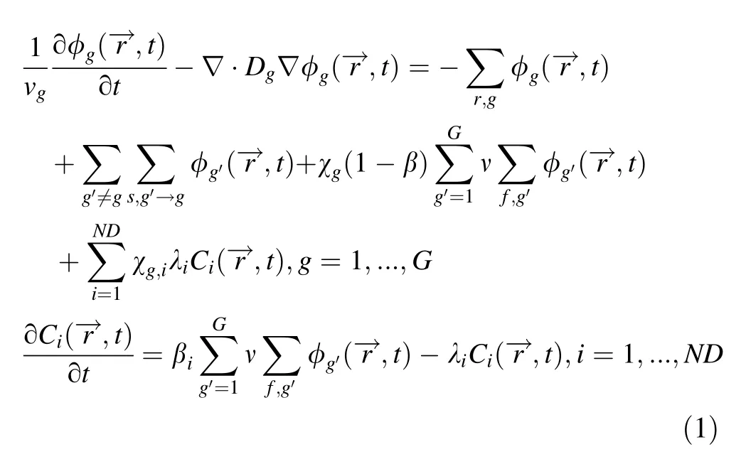
A detailed explanation of these variables can be found in[8]. In this study, the two-group method is adopted, which means that thermal neutrons are treated as one group (energy <0.1 eV)and the energy of the other energy group is greater than Ec, where Ecis the delimitation energy(~0.4 eV).
This NDK code based on the neutron diffusion equation was developed.Its result was compared with a 2D-TWIGL benchmark and demonstrated good agreement [8]. For the transient diffusion equation, because it is a time-rigid equation,the implicit difference scheme is selected to solve the equation on the time scale. At each time step, it is reduced to a neutron diffusion equation with a fixed source term.
3 Coupling approach
In this study,the UDF of Fluent was used to realize the data exchange between Fluent,KMC-sub,and NDK.The‘masterslave’mode was selected for coupling,in which FLUENT was used as the‘master program,’’while the‘‘slave code’KMCsubandNDKcouplingcode were compiledintoDynamic Link Library (DLL), as shown in Fig. 1a. The ’master program’FluentcallsDLLfilethroughUDFtorealizedataexchangeand process control.Once the two programs are coupled under the control of Fluent, data exchange occurs in the ‘master program’’boundary condition.
In our previous work, an explicit sequential coupling scheme between Fluent and KMC-sub was implemented,and a steady case and transient case were completed[7].To expand the scope of coupling subjects,a multi-physics and multi-scale coupling scheme is proposed in this paper, as shown in Fig. 1b.
The UDF can receive the data on the boundary from KMC-sub by calling the API functions in DLL files and sends the boundary data to the KMC-sub/NDK coupling code in each CFD time step, where the KMC-sub-module transmits the temperature of the coolant,cladding,and pellet to the NDK module, while the NDK module transmits the spatial distribution of power to the KMC-sub-module. The data transferred between the ‘‘master program’ Fluent and the DLL is mainly the coolant temperature, pressure, and mass flow at the inlet and outlet of the core.

Fig. 1 (Color online) Data exchange method and the coupling approach
To flatten the power distribution,the core assemblies are usually divided into several zones loaded with fuels of different enrichments.When Fluent transfers the data to KMCsub at the boundary in a fuel zone, the temperature and pressure are the average values of the Fluent interface,while the mass flow is the sum of the Fluent interface,and KMCsub calculates the flow mass rate distribution of each assembly in this zone,according to the flow-split model.The data transferred from KMC-sub to Fluent are transferred according to the division of fuel assembly zones, and the pressure and temperature on the Fluent interface of different zones were obtained from the average value of the number of KMC-sub-assemblies in the corresponding zone, while the mass flow of the Fluent interface was obtained by the sum of the number of corresponding KMC-sub-assemblies.
In this study, the time-explicit method was used in the coupling scheme. The three coupling codes have their own time steps and converge residuals,and Fluent can control the time advancement of the KMC-sub/NDK module through the UDF to maintain the same calculation time as Fluent. The KMC-sub-module and Fluent have the same time step,while the NDK module has a much smaller time step than Fluent,one-tenth of the Fluent time step. At the beginning of each time step, Fluent starts the iterative calculation. After convergence or reaching the maximum number of iteration steps,the data are transferred to the KMC module,then the KMC sub-module starts the iteration. After the KMC-sub-module converges,the temperature parameters are transferred to the NDK module, and the NDK module performs the iterative calculation. When the NDK module converges and reaches the same time as the KMC-sub-module, the NDK module transfers power to the KMC-sub-module;otherwise,the NDK module continues to increase the number of time iterations.When the overall time of the three modules is the same,the KMC sub-module transfers the data to CFD, and the next iteration begins. In each step of the calculation, an absolute error limit and a specified number of steps were used for each code as their convergence conditions.
The overall structure is an explicit sequential calculation, and the data are exchanged at the end of a time step.When the CFD reaches the set time or converges residuals,the overall calculation is terminated.
4 Application of the coupled code Fluent/KMCsub/NDK
4.1 M2LFR-1000 reactor
M2LFR-1000 is a typical pool-type lead-cooled fast reactor (LFR) proposed by the University of Science and Technology of China (USTC), which has completed the overall conceptual design and preliminary safety analysis[17-19]. The overall design of M2LFR-1000 is shown in Fig. 2, and the detailed design parameters of M2LFR are shown in Table 1.

Fig. 2 (Color online) The overall design schematic of M2LFR-1000
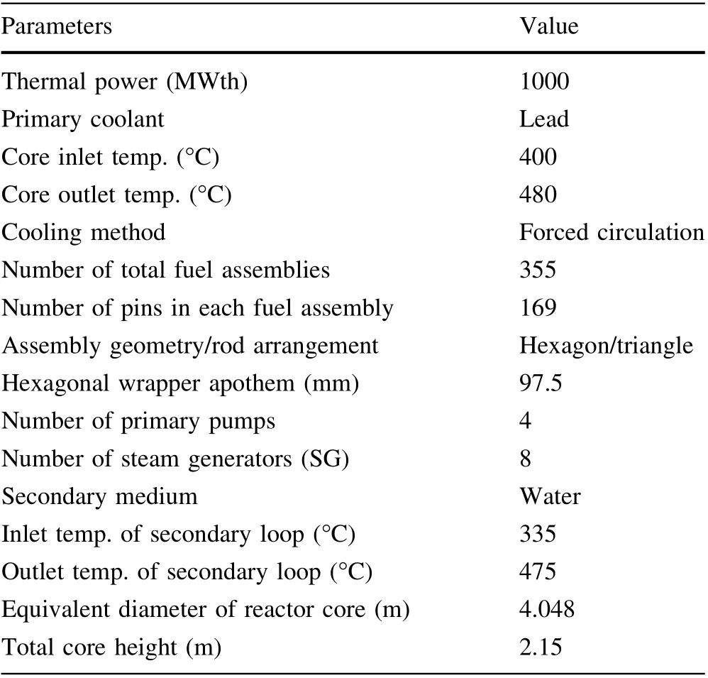
Table 1 The design parameters of M2LFR-1000
4.2 Description of the shutdown process
To evaluate the performance and accuracy of the Fluent/KMC-sub/NDK coupling program, a reactor shutdown process simulation was carried out and was compared with the results obtained from ATHLET3.1, which is a system analysis code for nuclear reactors or facilities [20]. The transient boundary conditions for this case are given below.
(1) First, the control rods and adjusting rods were not inserted. When shutting down, all control rods were inserted within 2 s.
(2) The reactor mass flow rate remains unchanged, and the variations in the coolant temperature and mass flow rate at the outlet of the heat exchanger are input from the ATHLET results through the UDF. This is displayed in detail in Sect. 4.3.
(3) The core decay heat power accounts for about 5%of normal power.
4.3 ATHLET model and its input conditions
To evaluate the results of the coupled program more reasonably, ATHLET3.1 was used to calculate the mass flow rate and temperature parameters at the outlet of the heat exchanger during the shutdown transient to provide boundary conditions for the heat exchanger in the coupled program. The ATHLET node diagram for M2LFR-1000 is shown in Fig. 3a, in which the reactor core is divided into four zones: the inner average fuel zone, inner hottest fuel zone, outer average fuel zone, and outer hottest fuel zone,which correspond to the inner and outer fuel assemblies in the core of M2LFR-1000, as shown in Fig. 3b.
In the ATHLET calculation model, the reactor was in steady-state operation before 0 s. From 0 s, 5100 pcm of negative reactivity is added within 2 s to simulate the reactor shutdown process, as shown in Fig. 4a. During the shutdown process, the pump speed remains constant, and the changes in the core power and primary circuit mass flow are shown in Fig. 4b. The change in the coolant temperature at the outlet heat exchanger is shown in Fig. 4c.
4.4 Model of coupling program
The domains of the three modules and their data exchange are shown in Fig. 5a,which is divided into three domains, where the hot plenum and cold plenum are calculated by Fluent to simulate the thermal-hydraulic phenomenon, while the core is calculated by KMC-submodule and NDK module to simulate the thermal-hydraulic phenomenon and physical state.
As shown in the C1 and C2 interface data mapping diagram (Fig. 5b), the geometry of KMC-sub consists of many assemblies, which are divided into inner and outer fuel zones. To solve the mapping problem between the coarse mesh adopted by KMC-sub and the finer mesh in the CFD model, the following method was used in this study.The average value parameter of each assembly simulated by Fluent is transferred to the subchannel code when Fluent transfers data to KMC-sub,while KMC-sub returns lumped parameters of each assembly to Fluent.
As for the reactor core, KMC-sub can calculate the spatial temperature distribution of the coolant, cladding,and pellet, and then transmits it to the NDK domain, and then updates the material’s absorption cross section according to the material’s temperature and calculates the distribution of neutron flux density. After renewing the neutron flux density, a new power distribution can be calculated and transmitted to the KMC-sub.
As shown in Fig. 5a, the cold plenum simulated by Fluent transmits the mass flow rate and temperature to the KMC-sub-module and NDK module at the first interface,whereas the hot plenum simulated by Fluent transmits the pressure to the KMC-sub-module and NDK module at the second interface. At the same time, the KMC-sub-module and NDK module transmit the pressure to Fluent at the first interface and transmit the mass flow and temperature to Fluent at the second interface.
4.4.1 CFD model
26.Godmother:The godmother did not become a common and well-known character in the Cinderella tale until Perrault incorporated her into his version of the story. Other versions of Cinderella in different cultures often have the heroine receive assistance from the deceased mother. The fairy godmother versions are the best known in Western culture thanks to Perrault and later versions from Disney and other sources.

Fig. 3 (Color online) ATHLET node model and the reactor core arrangement of M2LFR-1000
In this study, the entire primary loop model, except for the reactor core, was built in Fluent using an unstructured mesh obtained from ICEM CFD, as shown in Fig. 5c. The number of meshes used for this simulation is approximately 3.86 million.In the CFD model,the inlet boundary was the reactor core outlet, where the mass flow rate and temperature were obtained from KMC-sub, and the pressure was transferred from Fluent to KMC-sub. The outlet boundary is the reactor core inlet and adopts a pressure outlet where the pressure is transferred from KMC-sub,and the mass flow and temperature are transferred from Fluent to KMC-sub. In addition, the outlet temperature and mass flow of the heat exchanger (see location A in Fig. 5b)provided by ATHLET is another inlet boundary condition of Fluent.
At present, it has been widely used by scholars to simulate the flow and heat transfer of liquid metals based on the modified full flow model and wall function method.The k-ε model was used to calculate the thermal stratification in the cylindrical hot pool of LMFBR, which is a liquid metal fast reactor [21]. The standard k-ε model, k-ε(RNG) model, and Reynolds stress model were used to investigate thermal stratification in the sodium reactor and compared to experimental results, which showed that the RNG model has a milder temperature gradient[22].The kε(RNG)turbulent model was used to calculate the primary cooling system of the lead-bismuth reactor, MYRRHA[23].In this study,the k-ε(RNG)model and standard wall functions were used to calculate the turbulent flow inside the entire primary loop.
4.4.2 Neutronic/thermal-hydraulic model
Because the KMC-sub-module and NDK module are written based on C++, the classes of KMC-sub and NDK were constructed,respectively,and the two modules realize the transfer and exchange of data through API functions written in DLL. In the iterative calculation of a time step,the temperature of the coolant and fuel rods are calculated by the KMC-sub and transferred to the NDK module through the corresponding relationship of coordinates.The neutron flux density distribution is calculated by the NDK module and transferred to the power density distribution of the KMC-sub-module,and the next time step calculation is carried out.
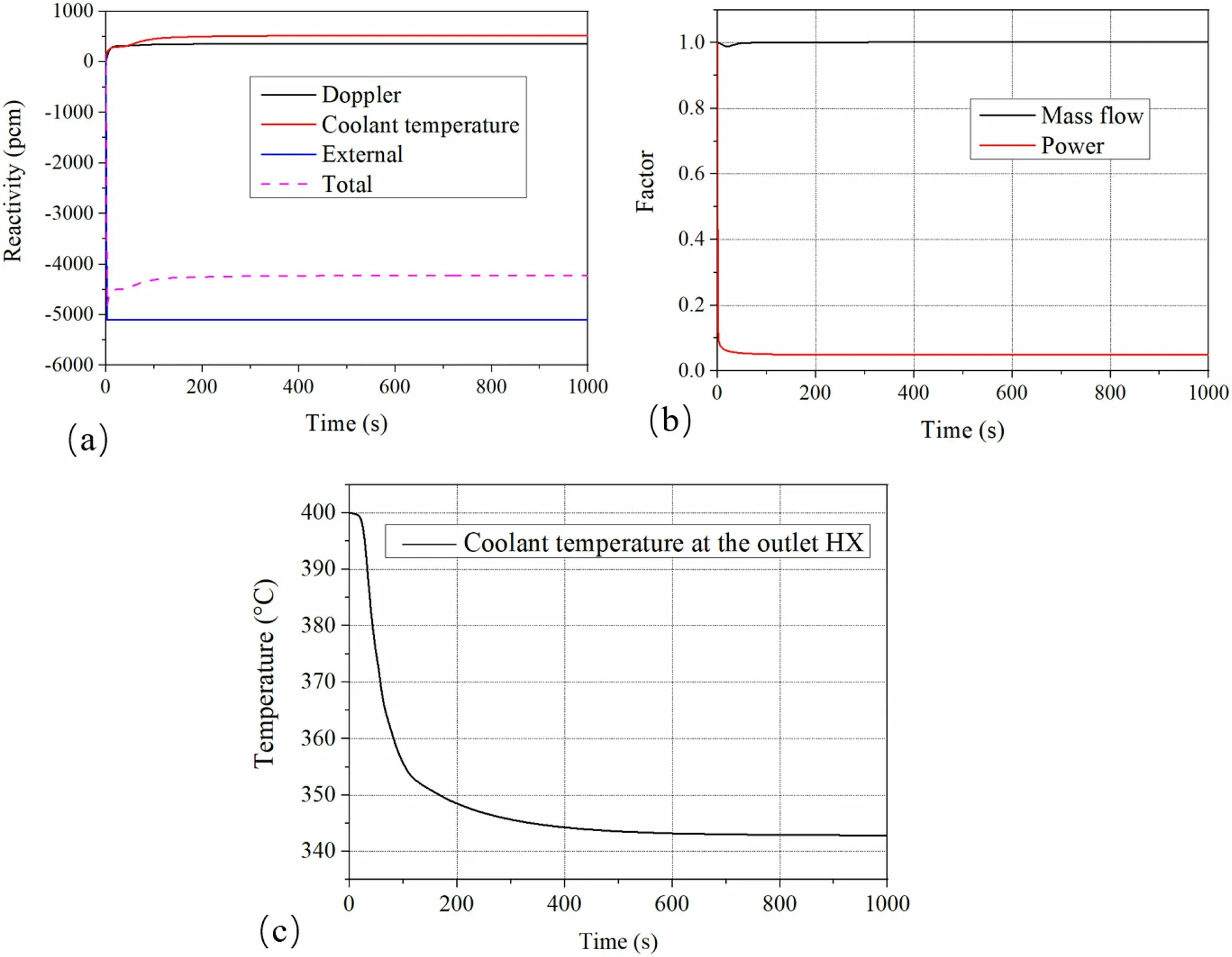
Fig. 4 (Color online) Calculation results obtained from ATHLET in the transient shutdown process
The KMC-sub-module and NDK module are coupled according to the mapping of the coordinate relation where the NDK code is built by the rectangular coordinate system,while the KMC-sub has a hexagonal mesh in every assembly. It is worth noting that NDK calculates the nuclear properties of materials in different areas according to whether the node coordinates are in the hexagonal assembly. As shown in Fig. 5d, only the x-y plane is shown, and the z-direction (axis direction) uses the same method to map mesh data with the corresponding height.Compared with the mesh in KMC-sub representing an assembly, the mesh size of the NDK module is much smaller. Additionally, a KMC-sub-mesh contains several NDK meshes. Each NDK mesh and KMC submesh have the coordinates of the center point.Before data mapping,it is determined whether the NDK mesh coordinates are in the KMC-sub-control volume.If it is,data mapping will be carried out; otherwise, it will continue to search for an NDK mesh that meets the determination conditions in a KMC-sub-mesh.
When KMC-sub transmits temperature data to NDK,one KMC-sub-mesh cell is mapped to multiple NDK mesh cells and transmits the same value to NDK; for power distribution transfer from NDK to KMC-sub, the average value of multiple meshes is adopted. Each time the mesh data mapping begins from the x-y plane first, then the zdirection is processed,and finally, the data transmission of different meshes is completed.
In the core calculation, the temperature distribution of the coolant, cladding, and pellet is simulated in the KMCsub-calculation domain; when the temperature distribution is transferred to the NDK calculation domain, the NDK module updates the cross section of the material according to the temperature, and then updates the core neutron flux density distribution, and then provides the corresponding power distribution to the KMC-sub-calculation domain.

Fig. 5 (Color online) Coupling domain division of M2LFR-1000 and mesh model
5 Analysis of shutdown transient of M2LFR-1000 and validation
5.1 Pre-simulation
A steady-state coupling in M2LFR-1000 is performed before the shutdown transient is implemented, in which Fluent first calculates independently to reach steady state,and then transfers coupling data with KMC-sub/NDK through UDF until all three codes reach a steady state.The heat source(reactor core)power shape and its value set into the first-step Fluent-alone calculation are obtained from the design values, which are calculated by the Monte Carlo code during the design stage.
Some local and global steady-state physical and thermal-hydraulic parameters are shown in Fig. 6 and Table 2,respectively.In addition,the design parameters are listed to verify the steady-state results obtained from the coupling program, and the value of the core pressure drop is obtained from the numerical simulation results in the preliminary design process.It can be seen from the results that the steady-state calculation results are in good agreement with the design values, laying the foundation for the following transient calculations.
5.2 Result and discussion
The transient shutdown calculation of the coupled program was based on the results of the above steady-state calculation. Figure 7a shows the power change calculated by the coupling program after shutdown, and because of the continuous insertion of control rods and the negative reactivity introduction reactor power drops quickly. When control rods arrive at the reactor bottom, the speed of power dropping becomes slow, and finally, the power reaches the level of decay heat.

Fig. 6 (Color online) Distribution of power and coolant temperature in the steady-state calculation

Table 2 Comparison of the global parameters of the steadystate calculation and design values
Figure 7b shows the average coolant temperature change at the core inlet and outlet calculated by the coupling program. It can be seen from Fig. 7b that at 0 s the coolant temperature in the coupling program and ATHLET are 500.8 and 495.8 °C, respectively. Then, as the reactor shutdown, the coolant temperature continues to decrease and finally stabilizes at 362.7 and 352.9 °C,respectively,at 250 s. At the same time, the highest temperature of cladding in the coupling program and ATHLET decrease from 530.6 and 526.1 °C to 363.1 and 354.6 °C, respectively.The highest temperature of the pellet decreased from 1654.6 and 1551.5 °C to 442.5 and 387.0 °C,respectively.Compared with the curve of power change,the temperature change has a certain lag, especially when the speed of the fuel pellet temperature decreases far exceeding that of the cladding and coolant because it takes time for energy to transfer in the rod bundles.
Figure 7c and d shows that the highest temperature of the coolant,pellet,and cladding calculated by the coupling program and ATHLET, respectively, change after shutdown. Comparing the calculation results between Fluent/KMC-sub/NDK and ATHLET during the shutdown process, the highest temperatures of pellet, cladding, and coolant calculated by Fluent/KMC-sub/NDK were all higher than those of ATHLET. This is mainly due to the lump-parameter method adopted in the ATHLET model,which has a certain number of pipes modeled as the reactor zone, and the maximum temperature is only the average value in this zone. However, all assemblies and subchannels in the Fluent/KMC-sub/NDK model were modeled separately,so the maximum temperature obtained was more accurate. In general, the maximum errors of the pellet, cladding, and coolant in the initial and final states were 14.3,2.4,and 2.8%,respectively,which demonstrates a good agreement with ATHLET, ensuring the correctness of the coupling program.
Another advantage of the multi-scale and multi-physical coupling program is that it can capture the three-dimensional phenomena of the reactor core. The contours of temperature and velocity distribution after shutdown are shown in Fig. 8, from which we can see that after reactor shutdown, there exists an obvious thermal stratification phenomenon within the upper plenum region. In reactor pools of liquid metal cooled fast reactors (LMFRs), especially in the upper plenum, the magnitudes of the inertial and buoyancy forces are usually of similar order[24].If the high-temperature liquid layer separates from the low-temperature liquid layer, the phenomenon called thermal stratification occurs. At the beginning of our simulation,thermal stratification occurred between the outer and inner regions of the upper plenum owing to the lack of coolant mixing in the upper core structure. In the early stage, the

Fig.7 (Color online)Calculation results of ATHLET and coupling program:a Power factor,b Coolant temperature at the core inlet and outlet,c Maximum temperature of pellet, d Maximum temperature of cladding and coolant
thermal stratification occurring between the outer and inner sides weakens, and the thermal stratification phenomena occurring between the top and bottom parts of the upper plenum begin to hold a dominant position.The Richardson number is introduced to distinguish the thermal stratification phenomenon in the reactor pool, which is used to judge the strength of the natural convection capacity and forced convection capacity [25]. g represents the acceleration of gravity, β is the thermal expansion coefficient of the lead coolant,D is the diameter of the upper plenum,ΔT is the coolant temperature change, and V is the velocity of the coolant. When the Richardson number is greater than one, thermal stratification occurs.

As shown in Fig. 8e-f, the coolant temperature at the reactor outlet decreases quickly, and because of the constant mass flow,the coolant with a lower temperature goes to the upper plenum at 10 s. At that time, the coolant temperature difference was 50 °C, the value of RI was 1.194, and the thermal stratification phenomena began to appear. Subsequently, the coolant temperature drops continuously, and at the same time, owing to the influence of buoyancy, the coolant with a higher temperature at the top of the upper plenum is gradually cooled by the heat exchanger,and then the reactor reaches a new steady state.At the same time, although the coolant mass flow remains constant,there are different velocity distributions owing to the coolant temperature at the outlet of the reactor decreasing continuously and the influence of buoyancy. In addition, from the perspective of engineering safety, this type of thermal stratification may cause the temperature boundary and stress effects of the surrounding structural boundaries to change, and further analysis of its influence is required by coupling the thermal-structural mechanics code.

Fig. 8 (Color online) Thermal-hydraulic parameter change vs time after shutdown: a and e the time at 0 s, b and f 10 s, c and g 50 s, d and h 250 s
Compared to the point reactor neutron dynamics model in ATHLET, the diffusion neutron dynamics model can capture the spatial variation of the neutron flux density in the reactor and evaluate the neutronic and thermal characteristics of the reactor more accurately. Figure 9a-d shows the contour of the neutron flux density changes with time at the horizontal section of the middle height of the core active zone. Initially, the control rod and safety rod were not inserted. During the shutdown process, all the control rods were inserted completely within 2 s, and because of the introduction of a large amount of negative reactivity during the control insertion, the neutron flux density of the reactor core decreased rapidly.In particular,around the control rod, the absorption of the control rod caused the nearby neutron flux density to tend to zero.

Fig. 9 (Color online) Transient change of neutron density and core outlet temperature vs time after shutdown: a and e the time at 0 s, b and f 10 s, c and g 50 s, d and h 250 s
When reaching a steady state, the distribution of the neutron flux density is relatively uniform.After the control rod is inserted, because of the role of the control rod, the neutron flux density presents a spatial change closely related to the position of the control rod.Further analysis of the change in neutron flux density with time and space shows that the overall neutron flux density decreases with time, but the neutron flux density in the core center is higher than that in other regions.
The Fluent/KMC-sub/NDK coupling program can consider physical and thermal-hydraulic interactions.Both the overall and local parameters, that is, the coolant temperature, fuel temperature, pellet temperature, and other thermal parameters of each assembly can be captured. During the shutdown process, the changes in the coolant temperature at the core outlet are shown in Fig. 9e-h. As time goes on, the temperature of the coolant at the outlet of the core decreases with time, which is the same as the change in the neutron flux density. Because the neutron flux density is relative to the reactor power, under the condition of constant inlet mass flow, the coolant outlet temperature gradually decreases. Further analysis of the spatial distribution of temperature shows that in the steady state, the temperature distribution is relatively uniform because the neutron flux density distribution of the reactor is also relatively uniform. With the insertion of control rods, the spatial distribution of power becomes higher at the center,which leads to the same distribution of coolant temperature.
However, at 250 s, the minimum temperature at the outlet of the core coolant appeared in the external fuel area because the neutron flux density of the reactor was very small and the heat generated by fission tended to zero,and the energy of the coolant was mainly provided by the decay heat of the radioactive products in the reactor.At this time,the dominant factor of the coolant temperature changes from power to inlet flow, and because the flow rate of the center is relatively higher than that of the corner in the assembly, the temperature of the external fuel area is higher than that of the central fuel area. By analyzing the simulation results of the Fluent/KMC-sub/NDK coupling program,it was found that the numerical simulation results were consistent with the actual reactor shutdown process,which shows that the calculation of the coupled program is reasonable and accurate, and can be used for the thermal safety performance evaluation of the reactor.
6 Conclusion
Based on the previously developed sub-channel code KMC-sub, neutron diffusion kinetic program NDK, a multi-physics and multi-scale program Fluent/KMC-sub/NDK was developed using ‘‘Master-slave’’ mode. The coupling scheme is explicit order, and the reactor core domain is simulated by KMC-sub and NDK, in which the
power and temperature distributions are transferred, while the rest of the domain of the primary loop is simulated by Fluent,where the temperature,mass flow,and pressure are transferred between KMC-sub and Fluent at the boundary.Based on the steady-state calculation, a shutdown process was carried out and compared with the ATHLET results for verification.The following conclusions can be drawn based on detailed analyses.
(1) A multi-physics and multi-scale program, Fluent/KMC-sub/NDK, was developed using UDF and an explicit coupling method, and a shutdown process was simulated and compared with ATHLET, finally demonstrating good agreement. At the same time,the change of neutron flux density distribution in the reactor core with time is observed successfully.
(2) In the process of shutdown, as the control rods are inserted within 2 s, the neutron flux density decreases rapidly, which causes the power to fall promptly. However, the maximum temperature of the coolant, fuel pellet, and cladding have a certain lag compared to power, especially the speed of fuel pellet temperature decrease far exceeding that of cladding and coolant. This proves that energy conversion is much faster than the transfer of energy between rod bundles.
(3) During the shutdown process, thermal stratification occurs in the inner and outer parts of the upper plenum at the beginning, and when the RI number exceeds 1.0, the thermal stratification phenomena occurring between the upper and lower parts of the upper plenum begin to hold a dominant position.Finally, the thermal stratification phenomena generally disappear, but there are some mild thermal stratification phenomena between the inner and outer parts of the upper plenum due to the lack of mixture in the upper core structure.Future work will focus on two aspects:(1)thorough and deep research on the interplay between time steps, spatial mesh size, and spatial stencils on the convergence and precision of the multi-scale and multi-physics coupling simulation, and (2) expanding the capability of the multiscale and multi-physics coupling program by implementing more sub-tools (i.e., secondary simulation programs, thermomechanical codes, etc.)
AcknowledgementsWe thank GRS for providing the ATHLET code.
Authors’ contributionsAll authors contributed to the study conception and design.Material preparation,data collection and analysis were performed by Xiao Luo, Chi Wang, Ze-Ren Zou, Lian-Kai Cao, Shuai Wang, Zhao Chen, and Hong-Li Chen. The first draft of the manuscript was written by Xiao Luo and all authors commented on previous versions of the manuscript.All authors read and approved the final manuscript.
杂志排行

Nuclear Science and Techniques的其它文章
- Anisotropy flows in Pb-Pb collisions at LHC energies from parton scatterings with heavy quark trigger
- A novel approach for radionuclide diffusion in the enclosed environment of a marine nuclear reactor during a severe accident
- Investigation of combined degrader for proton facility based on BDSIM/FLUKA Monte Carlo methods
- Anisotropic flow in high baryon density region
- Effect of relaxation time on the squeezed correlations of bosons for evolving sources in relativistic heavy-ion collisions
- Superconducting multipole wiggler with large magnetic gap for HEPS-TF