Superconducting multipole wiggler with large magnetic gap for HEPS-TF
2022-05-13XianJingSunFuSanChenXiangChenYangWanChenXiaoJuanBianMinXianLiRuiGeMiaoFuXuYaoGaoJinCanWangHuiHuaLuJianSheCaoZhiQiangLiZhuoZhangRuiYeXiangZhenZhangShuaiLiBaoGuiYinMeiYangLingLingGongDaHengJiLinBianR
Xian-Jing Sun· Fu-San Chen,3· Xiang-Chen Yang· Wan Chen ·Xiao-Juan Bian · Min-Xian Li · Rui Ge · Miao-Fu Xu · Yao Gao ·Jin-Can Wang · Hui-Hua Lu · Jian-She Cao · Zhi-Qiang Li ·Zhuo Zhang · Rui Ye · Xiang-Zhen Zhang · Shuai Li · Bao-Gui Yin ·Mei Yang · Ling-Ling Gong · Da-Heng Ji · Lin Bian · Ran Liang ·Ya-Jun Sun · Hong Shi
Abstract A 16-pole superconducting multipole wiggler with a large gap of 68 mm was designed and fabricated to serve as a multipole wiggler for HEPS-TF. The wiggler consists of 16 pairs of NbTi superconducting coils with a period length of 170 mm, and its maximum peak field is 2.6 Tesla.In magnet design,magnet poles were optimized.Furthermore, the Lorentz force on the coils and electromagnetic force between the upper and lower halves were computed and analyzed along with the stored energy and inductance at different currents. To enhance the critical current of the magnet coil,all the pole coils selected for the magnet exhibited excellent performance, and appropriate prestress derived from the coil force analysis was applied to the pole coils during magnet assembly. The entire magnet structure was immersed in 4.2-K liquid helium in the cryostat cooled solely by four two-stage cryocoolers,and the performance test of the superconducting wiggler was appropriately completed. Based on the measured results,the first and second field integrals on the axis of the superconducting wiggler were significantly improved at different field levels after the compensation of the corrector coils. Subsequently, the wiggler was successfully installed in the storage ring of BEPCII operation with beams.
Keywords Superconducting multipole wiggler · Force analysis · Quench protection · Magnetic field measurement · HEPS-TF · Cryostat
1 Introduction
High energy photon source (HEPS) is a high-performance and high-energy synchrotron radiation light source with a beam energy of 6 GeV and an ultra-low emittance of better than 0.06 nm rad [1-3]. HEPS is mainly composed of accelerator, beamlines, and end-stations. In the research and development project for HEPS, HEPS Test Facility(HEPS-TF), a series of accelerator techniques required for constructing a diffraction-limited storage ring light source were thoroughly studied [4, 5] and have been demonstrated. Superconducting wiggler (SC wiggler), as a high performance insertion device to obtain hyperspectral brightness, is one of the most important instruments for HEPS-TF. When compared with the international research on high-performance insertion devices, this technology should be improved and strengthened to satisfy the requirements of the booming synchrotron radiation source.
Additionally, the new SC wiggler is used to replace the existing permanent magnet wiggler 3W1 for Beijing Electron Positron Collider Upgrade Project (BEPCII)whose field is too weak for conducting necessary experiments [6]. Simultaneously, the impact on the peripheral equipment should be minimized due to the SC wiggler installation. Given that BEPCII is a dual used storage ring for circular collider and synchrotron radiation,the new SC wiggler should satisfy both operation modes[7].It requires a vertical beam aperture of 39 mm and it results in a magnetic gap of 68 mm, which consists of the inside wall of the liquid helium tank,60-K thermal shield,and vacuum chamber at room temperature. SC wiggler with the complex structure was designed and fabricated in the HEPS-TF project [8, 9].
The period length of the SC wiggler is 170 mm and peak field is 2.6 T as the requirements. It is a significant challenge to design and build a large magnetic gap SC wiggler with high peak field[10].Moreover,given that the coil size is large and it conducts high current, the stored electromagnetic (EM) energy is significantly high. This results in high inductance and generation of a high reverse voltage when a quench occurs [11]. Effective measures were determined to solve the challenges mentioned above such that the SC wiggler was successfully developed. The main parameters of the SC wiggler are listed in Table 1.
2 Construction of the SC wiggler
The SC wiggler is comprised of magnet, cryostat, current lead, power supply, and quench protection. Furthermore, according to the beam aperture of the new wiggler and its connection with the upstream and downstream, the appropriate vacuum chamber is manufactured.
2.1 Magnet
A magnet with multiple poles is the core part of the SC wiggler. The magnet includes coils, iron cores, flux return yokes,and stainless steel support plates[12].In the process of the magnet design, 3D code, Opera Tosca, which is based on finite element analysis, is used for the parameter optimization to satisfy the required magnetic field and toconduct electromagnetic force analysis. All relevant parameters for these components were carefully calculated,and they were finally set for fabrication.

Table 1 Main parameters for design and construction of SC wiggler
2.1.1 Magnet design
There are even number of magnet pole pairs, 16 pairs,wherein 14 pairs correspond to the main poles and 2 pairs correspond to the end poles[10].Each main pole is wound with a single NbTi string,and the end poles are wound with two strings, one for the wiggler field and the other for correction. Given that the magnet uses the asymmetric structure, the first field integral with respect to the longitudinal axis remains zero with respect to different currents[13].By carefully designing the end poles,the second field integral is close to zero at a fixed current. The practical non-zero field integrals only occur due to the imperfections in manufacturing and assembling. However, these errors can enlarge the second integral field to a certain extent.To reduce the first and second field integrals, the corrector coils of the end poles can be used for compensation.
All the superconducting coils are wound with NbTi wires manufactured by Western Superconducting Technologies Co., Ltd. The superconducting wire exhibits a copper to NbTi ratio of 1.3 and higher critical currents,i.e.,604 A in a magnetic field of 7 T and 408 A in a field of 8 T.Its bare dimensions are 1.20 mm × 0.75 mm,and the insulation thickness of a single side is 0.04 mm. The socalled residual resistivity ratio (RRR) exceeds 100. To boost the performance of the magnet and avoid large fringe fields, the ferromagnetic materials of DT4 pure iron are used for iron poles and yoke iron of the upper and lower halves. This can improve the peak magnetic field by more than 20% when compared with the non-ferromagnetic materials. The NbTi wire is wound around iron poles,which are composed of DT4 pure iron block.
All the superconducting wiggler coils, which consist of 14 pairs of main coils and 2 pairs of end main coils, are welded in succession. The maximum design current of the main coil is 400 A. As shown in Fig. 1a, the main coil corresponding to the ferromagnetic pole exhibits the shape of racetrack with an inner bending radius of 21 mm at both ends and a straight line length of 180 mm. In all the pole coils, the gap between the iron core and main coil is 0.5 mm, which is used to wrap the insulated materials before winding the coil. The total width of each main pole is 84 mm and there is a gap of 1 mm between adjacent main pole coils. This space is reserved for epoxy impregnation and reducing difficulties during assembly. To improve magnetic field quality in the good field range, the shapes of the end iron poles are optimized by changing the pole width and slotting in the middle of the pole, which slightly differ from the main iron poles.
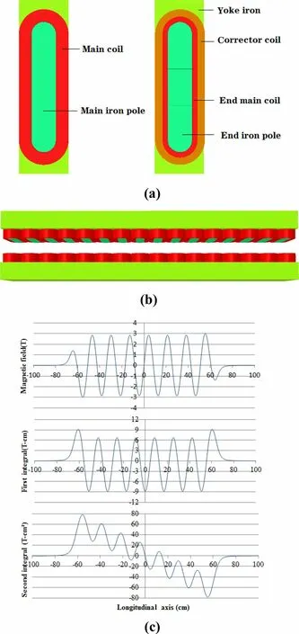
Fig. 1 (Color online) 3D simulation model and magnetic field distribution of SC wiggler.(a)Main pole and end pole;(b)3D model without support plates; (c) Magnetic field distribution along the longitudinal axis at a design current of 400 A
Table 2 lists all the optimized parameters of the main poles and end poles. Based on the numerical simulations with a model in Fig. 1b,the vertical magnetic field strength along the longitudinal axis as well as first and second integrals are realized. Figure 1c presents the simulated results at a design current of 400 A.The vertical peak field is 2.8 T and first and second field integrals are close to zero. Furthermore, the magnetic field deviation, ΔB/B, ofthe central pole along the transverse axis is better than 0.2% within a good range of ± 23 mm. This range is sufficient to correct some of the consequences due to some misalignments.

Table 2 Single pole parameters
For the SC wiggler, there is always a large current on each conductor of the coils, and the electromagnetic force on current-carrying conductors cannot be ignored. When the magnet is excited with a high current, the sectional wires can potentially slightly move due to the induced Lorentz force. This type of small local movement of wires can result in quench. To avoid this, sufficient prestress should be applied to all the coils on the sides [14]. The relation among the magnetic field, current density and Lorentz force is as follows:
where FLorentzdenotes the Lorentz force on the conductor,J denotes the current density on the conductor, B denotes the magnetic field on the conductor, and V denotes the current-carrying volume. In the racetrack coil of the wiggler magnet, maximum magnetic field occurs at the arc sections of the coil ends,which is 6.4 T at a current of 400 A.In this case,the Lorentz force on the main pole coil can be calculated and analyzed. Figure 2a presents the values and directions of the Lorentz force at the different parts of the racetrack coil at 400 A.
The total electromagnetic force between the upper and lower halves can be computed via integration of the full Maxwell stress tensor over the mid-plane between the poles as follows:
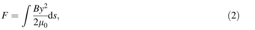
where F denotes the integrated force with respect to area S on the mid-plane, By denotes the magnetic field in the mid-plane,and μ0denotes the permeability of vacuum.The total electromagnetic force between poles for the wiggler is simulated as 420 kN. Accordingly, the support plates with special structure, which maintain the mechanical strength and reduce weight, are designed. Figure 2b shows the magnet structure with the support plate. In this case, the end plates and support plates of the magnet are fabricated from stainless steel.

Fig. 2 (Color online) Force analysis on the pole coil and magnet structure. (a) Force on the pole coil at 400 A; (b) Magnet structure

Fig. 3 Stored energy and inductance versus excitation current
The stored EM energy in the wiggler magnet is crucial for circuit protection design. Hence, the calculation and analysis of the stored energy is also important for the choice of the quenching mode and dump resistor, which is closely related to the decay time of the current of the magnet. Owing to energy and inductance as functions of excitation current,the inductance can be deduced from the stored energy. Furthermore, these parameters are calculated in our simulations.Figure 3 illustrates the variation in the stored energy and inductance with respect to the loading current.The stored energy of the magnet increases as the current increases, and the energy reaches 289 kJ at 400 A. The inductance is significantly high when the current is low. As the current increases, the inductance continuously decreases from 18.9 H at 5 A to 3.6 H at 400 A.This is due to the fact that iron cores gradually saturate as the current increases,and the permeability of the iron cores gradually decreases and approaches vacuum permeability.For the wiggler,the inductance varies in a wide range such that the stored energy is extremely high at the high current values. This leads to higher requirements in terms of accuracy in detecting the quenches and speed of stored energy transfer.
With the exception of the main coils,there are two pairs of corrector coils. Each pair of corrector coils at the entrance or exit is connected in series and powered individually.The maximum current of the corrector coils is set to 20 A and accounts for 5% of the design current of the main coil, which can provide sufficient adjusting capacity.
2.1.2 Magnet fabrication and test
The pure ferromagnetic poles are treated with rust prevention before winding.All the pole coils of the magnet are fabricated using the technique of dry winding directly on the insulated iron poles. The main coils of the magnet,including the main coils of the end poles,are wound in the same direction. To identify the direction of the corrector coil current while adjusting the magnetic field,the winding direction of the end pole corrector coil is the same as that of the corresponding main coil.The coil should be covered with the ground insulation after winding.
Subsequently, vacuum impregnation is performed on each pole coil as shown in Fig. 4a.Each coil of the middle poles is impregnated separately, and the main coil of the end pole is impregnated together with the corrector coil.During the performance test for pole coils, five pairs of pole coils are tested together at the same time, and two opposite pole coils of each pair are connected in series.When the quench occurs, it can be determined as to which coil is quenched based on the information of quench detection. The quench detection system is connected at both ends of each coil. The coils that are identified as quenching too many times can be excluded and other coils can continue training to determine whether the coils can conduct the required current. Among all the tested coils tested, only coils with excitation current exceeding 400 A are eligible.Finally,28 main coils and 4 end pole coils are selected from all the qualified coils based on quenching times and appearance of coil damage.
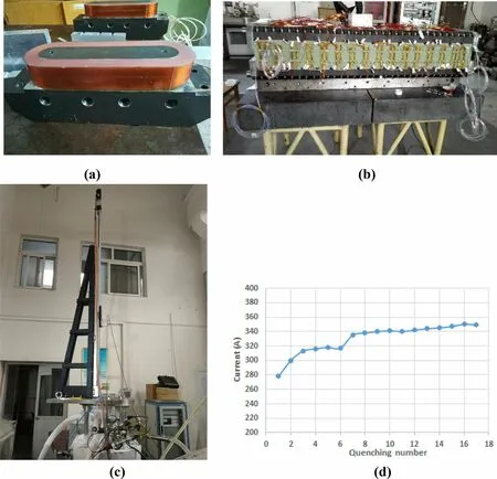
Fig. 4 (Color online) Magnet fabrication and vertical test. (a) Pole coil; (b) Magnet assembly; (c) Vertical test; (d) Magnet training process
To avoid frictional heating and quenching due to the coil movement owing to the magnetic force, the required prestress, which is in the opposite direction of the Lorentz force on the coil,is applied to the coils when the magnet is assembled.Based on the calculated results of the coil force,the prestress should exceed the maximum Lorentz force on the coil at the design current and the pressure of no less than 20 MPa for the magnet. Each half magnet is first preassembled. Using the pressure-sensitive paper between the coils of the adjacent poles, the prestress on the coils at different positions is detected. According to the pole structure and stress condition, the fillers with appropriate thickness and suitable elasticity are affixed at the edge of the coil. Hence, uniform preloading force is applied at the linear section of the coil.At both ends of each coil,arc G10 blocks are added to increase the prestress force when the support plates are assembled.
The overall assembly of the magnet is completed after the coil connections as shown in Fig. 4b.All the main coils are interlaced and connected in series. The currents in the opposite pole coils are in the same direction such that the magnetic field produced in the mid-plane is the same.However, the coils of adjacent poles produce an opposite magnetic field, and the currents are also in opposite directions.Similarly,the corrector coils of two pairs of the end poles are connected in a similar manner as the main coil of the same pole.
The magnet is installed in the Dewar used for the vertical testing of superconducting magnets. The Dewar contains a vacuum insulation layer, which can prevent the radiated heat from the surroundings and reduce the consumption of liquid helium.The Dewar can accommodate a certain amount of liquid helium besides the magnet. The vertical test of the magnet for the SC wiggler is performed as shown in Fig. 4c. The maximum excitation current is 350 A after 15 quenches, and then another quench occurs.Then, the magnet is restored to superconductivity by pouring liquid helium directly into the Dewar, and the excitation current is less than 350 A when it is excited again.At a current of 345 A,the magnetic field is measured on axis of the magnet and the peak field is 2.6 T.Given that a large amount of liquid helium is consumed, the magnet does not undergo further excitation when the test field satisfies the requirement of 2.6 T. Figure 4d presents the entire process of magnet training.
2.2 Cryostat and current lead
In the case of the SC wiggler,the entire magnet structure is completely immersed in the liquid helium of the cryostat at 4.2 K. Figure 5a shows the cryostat structure of the SC wiggler [15-17]. In the outer part of the cryostat, a 60-K thermal shield with appropriate cooling tapes is placed between the liquid helium tank and stainless steel chamber to reduce the radiation heat load from the external stainless steel chamber.Within the magnetic gap of 68 mm,a liquid helium tank with a thickness of 6 mm, a 60-K thermal shield with a thickness of 2 mm and a beam vacuum chamber operating at normal temperature are placed. The outer side of the vacuum chamber is rectangular,inner side is elliptical,and gap in the central region is 39 mm.This is necessary for the beam of a dual-used storage ring [18].The vacuum chamber should provide an ultrahigh vacuum with a pressure of 10-8Pa during the beam operation.This prolongs beam lifetime and blocks the radiated heat from beam loss via the resistive wall impedance of the beam vacuum chamber.
Fig. 5 (Color online) Cryostat and current leads. (a) Cryostat structure of SC wiggler; (b) Assembly model of current leads
There are four cryocoolers with stages of 4.2 K/50 K for the thermal shield,and they support long-period operation.Two of the cryocoolers are placed on the top and the other two are placed on the bottom. The warm ends of the high temperature superconducting (HTS) current leads are cooled by the first stages of two cryocoolers at the top,whereas the cold ends of the HTS current leads are cooled by the second stages.The 60-K thermal shield is cooled by the first stage of four cryocoolers at the top and bottom.The recondensers, which reliquefy vaporized helium gas,are cooled by the second stage at the top, while the liquid helium vessel, owing to heat conduction, is cooled by the second stage at the bottom. The static heat load of the cryostat with an allowance factor of 1.5 is 4.5 W/149.9 W at 4.2 K/60 K. The total cooling capacity of these cryocoolers,which corresponds to 6 W/200 W at 4.2 K/60 K,can satisfy the heat load requirements of the SC wiggler.The overall size of cryostat is 1989 mm (Length) × 1404 mm (Width) × 2347 mm (Height), which can satisfy the requirements of installation space in BEPCII tunnel.
The current leads are connected with both ends of the SC wiggler coil circuit. The leads are used for smooth current transition from the superconducting to the normal conducting state [19]. In SC wiggler, the current leads are the main heat source of heat transfer for the cryogenic system, and they are permanently welded to the superconducting coils. Hence, the choice of the materials and connection mode with respect to the current leads are very important. To satisfy the low heat load, the current leads made of copper wire and high-temperature superconducting wire are adopted and better ability to carry currents for the transition [8]. Figure 5b shows the assembly model of the current leads. There are three pairs of current leads for the SC wiggler. One pair of current leads connected to the main coils can withstand 400 A. Furthermore, other two pairs of current leads connected to corrector coils can withstand 20 A. One end of the HTS current leads, which are cooled by the cryocoolers at the top, is connected with SC Nb-Ti coils, and the other end is connected with brass current leads. Before the current leads are formally installed, the performance test of the current leads is conducted on the dedicated test platform. The test results indicate that the performance of the current leads exceeds the requirements. Additionally, the temperatures and voltages of HTS current leads and superconducting coils are monitored via quench detection, and the corresponding information is included in the SC wiggler interlock for the quench protection system.
2.3 Quench protection and power supply
Three power supplies are required for the SC wiggler,which consists of a main power supply of 580 A/7 V for the main coils and two corrector power supplies of 65 A/5 V for the two pairs of corrector coils. The output voltage turbulence is less than 50 ms, current stability of the main power supply exceeds 50 ppm, and corrector power supply exceeds 100 ppm.
The SC wiggler main coil should exhibit features of high stored energy, high inductance, and wide range of inductance variations with the different currents. Hence,although difficult, it is necessary to accurately detect the quenches and transfer the stored energy in a timely manner to protect the coils from damage due to the release of heat when the magnet quenches. Given the aforementioned features of the SC wiggler and relatively small Cu/Sc superconducting wire, an active quench protection scheme composed of a digital quench detector and a new type of super protection circuit is adopted. Furthermore,strict requirements are introduced for the quench detection speed and current attenuation speed when a quench occurs[20]. To increase the speed of current attenuation, a set of high voltage maintenance circuits are adopted as an effective solution. They are used to replace the traditional pure dumping resistor. In case of quenches, a reverse high voltage of up to 1000 V can be maintained at both ends of SC coil until the current decays to zero. This dedicated designed scheme of the quench protection provides reliable operation for the SC wiggler.
3 Test and data analysis of SC wiggler
The vertical test of the magnet led to valuable data.The current rate directly affects the stability of the magnet and leads to a quench.After performing many experiments,the suitable current rate of the magnet excitation is finally obtained for safe operation.The rising rate of the current is 0.2 A/s under 300 A and 0.1 A/s above 300 A, while the falling rate of the current is 0.2 A/s for all current values.
The critical current of the magnet is gained via the training process during the vertical test, which is accompanied by multiple quenches. According to the test results with a critical current of 350 A, the maximum allowable current is 345 A.

Fig. 6 (Color online) Magnetic field measurement for SC wiggler.(a) Magnetic field measurement; (b) Measured and simulated results on axis of SC wiggler at 345 A
After the magnet is installed in the cryostat(Fig. 6a),the magnetic field measurements are conducted via the Hall probe for magnetic field distribution and stretched wire for the first and second field integrals [12, 21]. Figure 6b shows a comparison of the simulated and measured fields on axis of the SC wiggler. Both peak fields correspond to 2.6 T at 345 A. The first and second field integrals for the SC wiggler vary with the excitation currents of the main coils. The first field integral can be effectively adjusted by changing the current of the single side corrector coil. The second field integral can be reduced by introducing the same current in the entrance and exit corrector coils. Furthermore, the first and second field integrals at different excitation currents can be reduced to small values according to the measured results. To enhance the efficiency, the magnetic field is compensated in the order of the first field integral and second field integral.Table 3 lists the required currents of the corrector coils at different main coil currents. Based on the measured data after correction,the current difference between the entrance and exit corrector coils corresponds to the required current values for compensating the first field integral, while the current of the exit corrector coil, along with the same current in theentrance corrector coil, is required for the second field integral. The measured results show that the first and second field integrals with the compensations can exceed the requirements.

Table 3 Integral magnetic field comparison before and after correction
The SC wiggler was successfully tested at IHEP in May 2019. Subsequently, it is installed in the storage ring of BEPCII as shown in Fig. 7. The SC wiggler with an operating current of 320 A, which is required for the synchrotron radiation, has been running steadily since its installation.The commissioning results show that a 50-keV high-energy X-ray photon flux is increased by 35 times than that of the old permanent magnet wiggler. Using the high-energy X-ray experimental platform with the SC wiggler,a series of important experiments were conducted.This has been highly appreciated by the users.
4 Conclusion
Superconducting wiggler with large magnetic gap was successfully developed for synchrotron radiation and collider operating mode under strict boundary conditions. By adjusting the corrector coil currents at both ends, the first and second field integrals under different peak magnetic fields can satisfy the requirements. During normal operation, the small cryocoolers can solely maintain the operation temperature for a long time. Using the dump resistors and high voltage maintenance circuit, the quench protection system can transfer most of the energy in timely and effective manner for the safe operation of the SC wiggler.The results of commissioning superconducting wiggler in the storage ring of BEPCII confirm that superconducting wiggler can completely satisfy the requirement of increasing the energy of synchrotron radiation and significantly broaden the application field of the original 3W1 beamline station.
AcknowledgementsThe authors are grateful to all IHEP accelerator members for their work on beam-related simulations and technical support. Furthermore, the authors are grateful to Zhan-Jun Zhang for his assistance.
Authors’ contributionsAll authors contributed to the study conception and design.Material preparation,data collection and analysis were performed by Xian-Jing Sun, Fu-San Chen, Xiang-Chen Yang,Wan Chen, Xiao-Juan Bian,Min-Xian Li, Rui Ge,Miao-Fu Xu,Yao Gao, Jin-Can Wang, Hui-Hua Lu, Jian-She Cao, Zhi-Qiang Li, Zhuo Zhang, Rui Ye, Xiang-Zhen Zhang, Shuai Li, Bao-Gui Yin, Mei Yang, Ling-Ling Gong, Da-Heng Ji, Lin Bian, Ran Liang, Ya-Jun Sun and Hong Shi. The first draft of the manuscript was written by[Xian-Jing Sun] and all authors commented on previous versions of the manuscript. All authors read and approved the final manuscript.
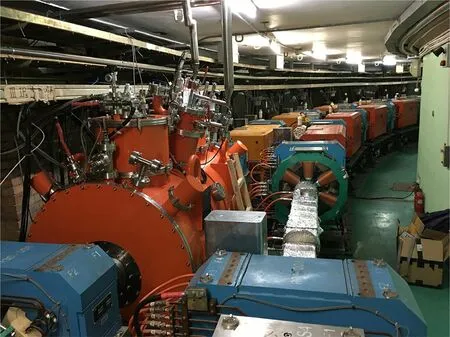
Fig. 7 (Color online) SC wiggler in the tunnel of BEPCII
杂志排行

Nuclear Science and Techniques的其它文章
- Anisotropy flows in Pb-Pb collisions at LHC energies from parton scatterings with heavy quark trigger
- Development and application of a multi-physics and multi-scale coupling program for lead-cooled fast reactor
- A novel approach for radionuclide diffusion in the enclosed environment of a marine nuclear reactor during a severe accident
- Investigation of combined degrader for proton facility based on BDSIM/FLUKA Monte Carlo methods
- Anisotropic flow in high baryon density region
- Effect of relaxation time on the squeezed correlations of bosons for evolving sources in relativistic heavy-ion collisions