Composite excitation multi-extension direction defect magnetic flux leakage detection technology
2022-05-05WEIMinghuiTUFengmiaoZHANGPengJIANGLixiaJIANGPengboJINGYu
WEI Minghui, TU Fengmiao, ZHANG Peng, JIANG Lixia, JIANG Pengbo, JING Yu
(1. School of Mechatronic Engineering, Southwest Petroleum University, Chengdu 610500, China;2. Kensington Campus, University of New South Wales, Kensington 2052, NSW)
Abstract: In the traditional pipeline magnetic flux leakage (MFL) detection technology, circumferential or axial excitation is mainly used to excite the magnetic field of defects. However, the domestic and foreign pipeline detection devices currently in operation are mainly axial excitation MFL detection tools, in which circumferential cracks can be clearly identified, but the detection sensitivity of axial cracks is not high, thus forming a detection blind zone. Therefore, a composite excitation multi-extension direction defect MFL detection method is proposed, which can realize the simultaneous detection of axial and circumferential defects. On the basis of the electromagnetic theory Maxwell equation and Biot Savart law, a mathematical model of circumferential and axial magnetization is firstly established. Then finite element simulation software is used to establish a model of a new type of magnetic flux leakage detection device, and a simulation analysis of crack detection in multiple extension directions is carried out. Finally, under the conditions of the relationship model between the change rate of leakage magnetic field and external excitation intensity under unsaturated magnetization and the multi-stage coil magnetization model, the sample vehicle towing experiment is carried out. The paper aims to analyze the feasibility and effectiveness of the new magnetic flux leakage detection device for detecting defects in different extension directions. Based on the final experimental results, the new composite excitation multi extension direction leakage magnetic field detector has a good detection effect for defects in the axial and circumferential extension directions.
Key words: composite excitation; magnetic flux leakage (MFL); multi-extension direction defect; pipeline detection
0 Introduction
In the petrochemical field, because the magnetic flux leakage (MFL) method has the advantages of fast detection speed, strong anti-interference ability, no coupling agent and suitable for large-area pipeline detection, it has been widely used for the inspection of defects in ferromagnetic tubes such as gas pipelines[1-4]. Generally, due to the relatively large volume of oil and gas pipelines, the traditional magnetization method to make the pipeline reach a local saturation magnetization state will inevitably lead to higher power consumption and larger volume of the magnetizer[5-7]. At the same time, due to the volume limitation, the MFL magnetizers in modern industrial applications can still only be magnetized in the axial direction, and defects in different directions cannot be fully and quickly identified, which may easily lead to missed inspections and increase the safety risk of the pipeline[8].
Aiming at the problems of MFL detection in multiple extension directions, Liu Bin used micro-magnetic signals to study the characterization of axial cracks in pipelines, and the research results indicated that the surface micro-magnetic internal on pipelines[9]. Yang Lijian analyzed the influence of the crack angle on the MFL detection signal and the characteristics of the crack MFL signal, and concluded that under a single axial excitation condition, only crack defects with a crack angle greater than 25° can be identified and cracks with a crack angle less than 25° cannot be accurately identified[10]. Wu Dehui proposed a new MFL detection method by using composite excitation, which superimposes the MFL DC magnetic field and the alternating magnetic field to detect axial defects with an eddy current field, and the DC field detects circumferential defects in the orthogonal direction to achieve no blind spot detection[11]. The above studies have contributed to the detection of circumferential or axial defects to a certain extent, but it is still relatively rare to discuss the problem of magnetization of defects in multiple extension directions at the same time.
This paper combines the characteristics and advantages of the circumferential excitation technology and the axial excitation technology, and proposes a method of combining the relationship model of the leakage magnetic field change rate with the change of the external excitation intensity in the unsaturated magnetization state and the multi-level coil magnetization model, and redesigns a new type of magnetizer and composite excitation multi-extension direction defect detection device. Subsequently, the new device is analyzed by finite element simulation with multiple extension directions by using simulation software. Finally, an experimental platform is built to verify and analyze the effect of the composite excitation multi-extension direction defect magnetic field leakage detection device on the detection effect of different extension direction defects, which provides a new idea for realizing the miniaturization and light weight of the magnetizer and reducing the occurrence of missed inspections.
1 System structure and detection principle
1.1 System structure
The structure of the new composite excitation magnetization detection system proposed in this paper is shown in Fig.1. This system includes a circumferential magnetized part and an axial magnetized part. Based on the volume limitation of the existing magnetizer, if the circumferential and axial magnetization excitation systems are included at the same time, the original huge magnetizer will become larger and the power consumption will be higher.
Therefore, for the circumferential magnetization part, a small U-shaped yoke magnetizer is used, and a detection method based on the change of external excitation and the change rate of leakage magnetic field is used to detect the defects in the axial extension direction, while reducing the volume and weight of the magnetizer[12-13]. The small circumferential unsaturated magnetizer is formed by winding a small amplitude AC coil and an unsaturated DC coil on the yoke. Small amplitude AC coil is evenly wound with enamelled wire with diameter of 1 mm on the skeleton of yoke for 20 turns, and the unsaturated DC coil is evenly wound with the same enamelled wire on the skeleton of two pole shoes for 200 turns. For the axial magnetized part, it consists of two solenoidal excitation coils connected with each other in series, and a small amount of direct current is supplied. Because the magnetic fields generated by the two coils are superimposed, a relatively uniform magnetic field will be generated, which can not only increase the effective magnetization time but also suppress the eddy current field generated in the high-speed detection process[14].
At the same time, the two parts are separated by corresponding spacing to further reduce the mutual interference of magnetic field[15]. In view of the current failure to detect cracks, this system has a good detection effect for defects in the axial and circumferential extension directions.
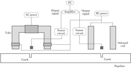
Fig.1 Structure of new detection system
1.2 Axial excitation principle
Since the secondary coil magnetization technology can not only suppress the eddy current effect to a certain extent, but also increase the magnetization time and complete the rapid magnetization of pipeline[7,16], so the secondary coil structure is adopted for axial excitation. Its principle is shown in Fig.2, whereI,RandBdenote the excitation current, the radius of the secondary coil and the magnetic induction intensity generated by the coil, respectively.
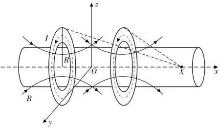
Fig.2 Secondary coil magnetization structure
In Fig.2, the two coils are energized by direct current, the magnitude and direction of the input current are the same, and the intensity of the magnetization field is controlled by the current of the input coil and the number of turns of the coil. The magnetic induction intensity at any point on the axis of the energized coil can be obtained by the vacuum Biot-Savar law in infinite uniform magnetic medium as Eq.(1), and then the magnetic induction intensity generated at any point on the central axis of the secondary coil can be obtained by the magnetic field superposition principle and Eq.(1), as shown in Eq.(2)[17].
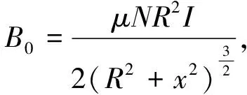
(1)
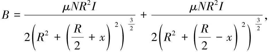
(2)
wherex,Nare the distance between coil center and any point on the central axis, and the coil number of turns.
Therefore, the magnetic field curve generated by the secondary coil can be obtained from Eq.(2), as shown in Fig.3.
QA,QBare the center points of two coils, respectively;Bis the magnetic induction intensity of the superposition of the two coils superimposed on the central axis. Fig.3 shows the magnetic field distribution of the magnetizing coil when the two coils are coaxially arranged. It is obvious that the superimposed magnetic field of the coil is a relatively uniform magnetic field, so the amount of change in the magnetic field intensity decreases, and the range of the uniform magnetic field increases. In the high-speed detection process, this can suppress the eddy current phenomenon among adjacent coils and reduce the influence of the magnetic after effect[18-19].
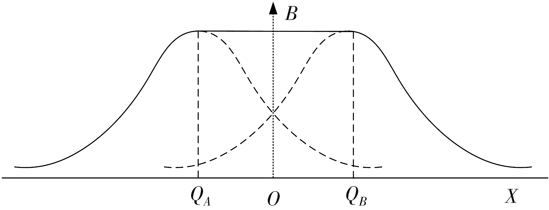
Fig.3 Magnetic field distribution
1.3 Circumferential excitation principle
In this paper, a magnetic pole-separated ring structure magnetizer is used for circumferential magnetization in the Fig.4, which is composed of 4 sets of U-shaped yokes with symmetrical structures[20-21]. The structure will form a circumferential magnetic field distributed around the inside of the pipe. Therefore,where there is an axial defect, a leakage magnetic field will be generated on the tube wall[22].
Since a variable-intensity non-saturated AC/DC composite excitation is applied to the magnetic pole separation magnetizer, and the traditional MFL detection method cannot detect the non-saturated magnetizer, this paper uses a detection method based on the external excitation change and the rate of change of the leakage magnetic field to detect the axial defect[13]. The detection principle of this method is shown in Fig.5.
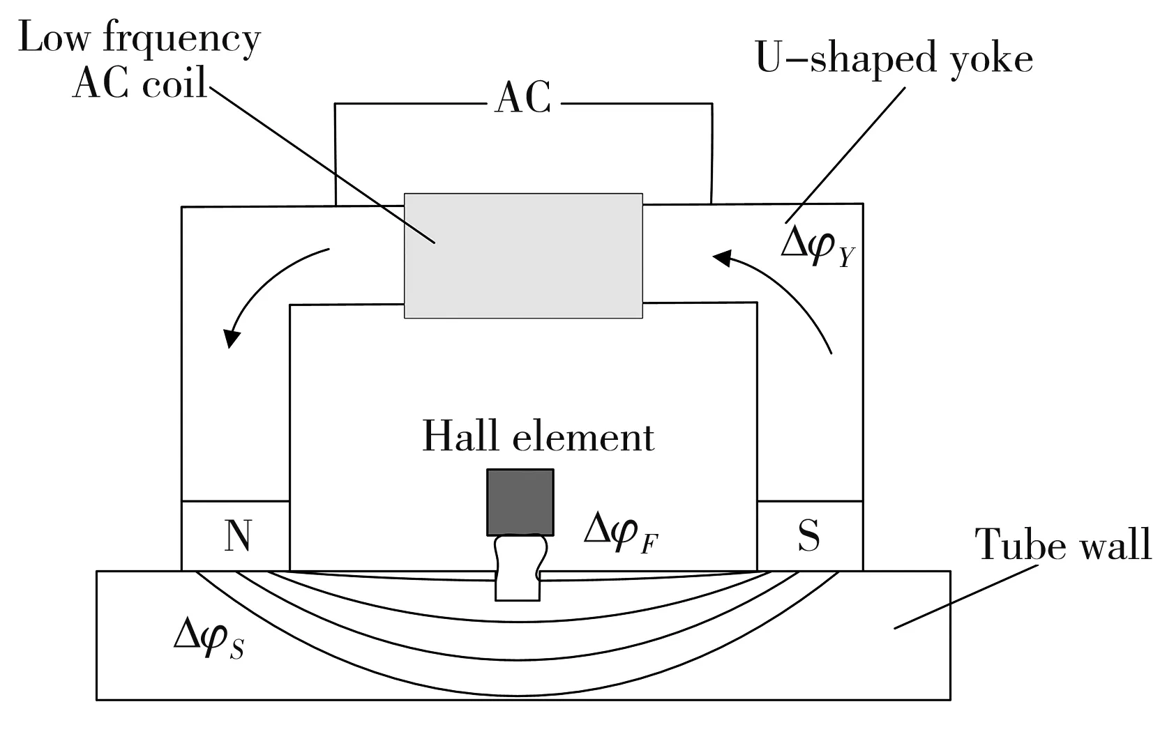
Fig.5 Principle of compound magnetization
In Fig.5, the entire excitation circuit is composed of the steel plate magnetization field and the air magnetization field, where the air magnetization field is equivalent to the leakage magnetic field[23]. Based on the basic principle of MFL detection, the change in magnetic flux between the air and the steel plate is still equal to the change in magnetic flux of the excitation field in the yoke under variable excitation conditions, as shown in Eq.(3).
ΔφY=ΔφS+ΔφF,
(3)
where ΔφY, ΔφS, ΔφFdenote Yoke flux variation, variation of magnetic flux in steel plate and air flux variation. When there is a defect in the pipeline, the magnetization field intensity at the defect inside the pipeline will increase significantly, which will cause the magnetic resistance at the defect to increase. And under the same variable excitation ΔφYcondition, the flux change ΔφSat the internal defect is also significantly smaller than that without defect. Therefore, the defect evaluation functionQ(·) can be defined by the ratio of the change in the internal magnetic flux of the pipeline ΔφSto the change in the magnetic flux of the yoke ΔφY[13]as shown in Eq.(4).
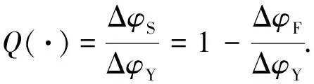
(4)
Based on the evaluation functionQ(·), defect detection can be realized indirectly by detecting the change of magnetic flux leaking into the air ΔφF.
Under normal circumstances, the actual magnetization is to achieve the total magnetic flux in the yoke through the excitation current, that is, the total magnetic flux in the yoke is set as a function of the excitation current, which isφY=φY(I). Therefore, the change in magnetic flux in the yoke ΔφYcan be expressed as
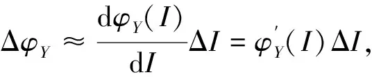
(5)
whereφY(I), ΔIdenote yoke flux as a function of excitation currentIand excitation current change.
It can be seen from Eq.(5) that the change in magnetic flux ΔφYis a function of the change ΔI. And the output voltage of the detection systemUMis a function of the detection value of the magnetic leakage field strengthBFin the air by the magnetic sensitive original in the detection system asBF=B(UM). Same as above, the change of the leakage magnetic field intensity ΔBFcan be expressed as
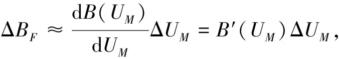
(6)
whereUMis leakage magnetic field detection output voltage.
In this article, the area of the leakage magnetic flux in the air is roughly constant, while the magnetic flux of the leakage magnetic field intensity in the air changes. Furthermore, the magnetic flux can be obtained from the integration of the magnetic induction intensityBand the areaS. Therefore, the change in MFL in the air ΔφFcan be calculated approximately as

(7)
whereSis the equivalent area of leakage flux in the air, and it is a constant.
Substituting Eqs.(5) and (7) into Eq.(4), the evaluation functionQ(·) can be obtained by
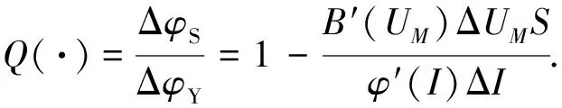
(8)
Obviously,B′(UM)/φ′(I) is a fixed value, so it can be made as a constant valueK.
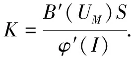
(9)
In summary, it can be obtained that
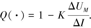
(10)
Obviously, the sensitivity of the Eq.(10) is determined by the fluctuation of the leakage magnetic field voltage and the fluctuation of the input excitation current, namely ΔUM/ΔI. In order to input the fluctuation value of the excitation voltage, the fluctuation value of the output voltage ΔUof the leakage magnetic field that can be detected by the magnetic sensor, the Eqs show that the detection method using the change of the excitation magnetic flux and the rate of change of the leakage magnetic field is feasible. However, in order to reduce the generation of errors, a small amplitude stable power supply is required, and in order to reduce the influence of eddy current effects, it is also necessary to use a low-frequency power supply for A/C excitation.
2 Simulation
In order to guide the design of the later detection system, firstly, the finite element simulation model of the secondary coil magnetization field is established, the secondary coil magnetization field with an interval of 1 cm-10 cm is calculated, respectively, and the best interval distance is selected through comparative analysis. Then, the interference between the circumferential and axial magnetization fields is analyzed theoretically. It is concluded that when the spacing between the two detection structures is greater than five times the radius of the secondary coil, the influence of the magnetic field interference of the two parts can be reduced to a certain extent. Finally, in order to verify that the proposed new magnetizer can correctly detect defects in any extension direction, a three-dimensional model is established, the magnetization effect is simulated and analyzed, and the influence of the angle between the magnetization direction and the extension direction of finite length defects on the distribution of leakage magnetic field is summarized.
2.1 Simulation of secondary coil spacing
In order to establish a more uniform magnetization field for the secondary magnetization coil in the ferromagnetic pipeline, the secondary coil simulation model is established. The specific model parameters are as follows: the secondary coil diameter is 13 cm, the number of turns is 200, the input current is 3 A, and the coil spacing is 1 cm-10 cm. The simulation results are shown in Fig.6.
It can be seen that with the increase of coil spacing, the width of the central magnetization field increases, while the magnetization intensity of the central uniform magnetization field decreases and gradually flattens. At the same time, considering the intensity and width of the uniform magnetization field, the best secondary coil spacing is 2 cm-4 cm.
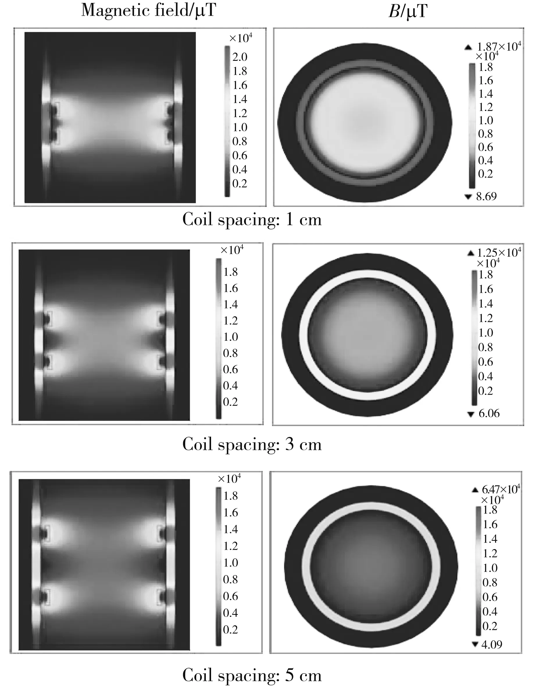
Fig.6 Simulation of secondary coils with different pitches
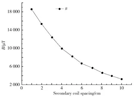
Fig.7 Magnetic flux density in central area
2.2 Magnetic field interference
In order to study the law of the magnetization field of two-stage coil and the interference to the circumferential magnetization field, it is necessary to calculate the corresponding separation distance of the two magnetization detection parts to reduce the magnetic field interference.
Therefore, the taylor series expansion of the Eq.(1) can be obtained by
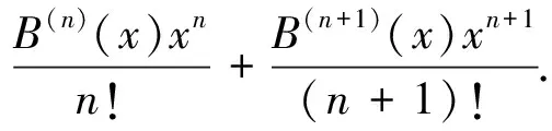
(11)
Whenx=0, that is, the center position of the two coils, all derivatives of the above Eqs except the second derivative are zero. In this case, the uniformity of the magnetization field is the best, and the central magnetic field intensity is the largest as in Eq.(5).
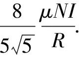
(12)
WhenX=5R, it can be obtained that
(13)
Obviously, the magnetic field at 5Ris more than two orders of magnitude smaller than the central magnetic field. At the same time, since the principle of the axial detection part is to detect the change value of the leakage magnetic field voltage, when the distance between the axial and the circumferential detection part is greater than five times the radius of the coil, the influence of the magnetic field of the two parts can be reduced to a certain extent.
2.3 Model establishment and simulation
As shown in Fig.8, the model structure of the new magnetizer includes pole separation ring structure and secondary coil structure, respectively. The axial magnetizer is a coaxial two-stage coil side by side, the coil diameter is 12 cm, the number of the turns is 200 and the input current is 3 A, and the optimal range between the two coils is about 2 cm-4 cm. The circumferential magnetizer is a ring-shaped structure with magnetic poles separated. In the yoke part, 20 turns of a coil are used as variable excitation, and a 0.1 T permanent magnet is used for DC excitation instead. At the same time, the distance between the two detection parts is set to 30 cm.
Parametric scanning is used to set the defects in the extension direction of 0°-90° on the pipeline. While stabilizing the direction of magnetization, the defects in the circumferential and axial directions are magnetized, and then the 0°-90° defect leakage magnetic field data is calculated as shown in Fig.9.
Fig.8 3D modeling of system
Fig.9 Comparison of defect magnetization effect
It can be clearly seen from Fig.9 that the axial magnetizer has a significant magnetization effect on the defects in the extension direction of 30°-90°, and the larger the angle, the better the magnetization effect. However, the magnetization of the defects in the extension direction of 0°-30° can hardly form an effective magnetic leakage field. The circumferential magnetizer has an obvious effect on the magnetization of defects in 0°-60° extension direction, and the smaller the angle, the more obvious the magnetization effect, but the magnetization of 90° extension defects can hardly form an effective leakage magnetic field.
Because theX-axis andZ-axis direction leakage magnetic field components have obvious characteristics in the MFL detection, theX-axis andZ-axis direction leakage magnetic field component changes are used to analyze the distribution of the leakage magnetic field when the defect extension direction changes from 0° to 90°. In Fig.10, the axial magnetization is used as an example to analyze the variation of the leakage magnetic fieldX-axis andZ-axis components of the leakage magnetic field under the condition of fixed magnetization with different extension directions.
In Fig.10(a), the larger the extension angle of the axial defect, the stronger the unimodality of theX-axis component of the leakage magnetic field, the larger the extreme value of the amplitude, and the smaller the width of the waveform, the more concentrated the waveform. On the contrary, the smaller the angle, the smaller the waveform characteristics. In Fig.10(b), as the angle between the magnetization direction and the defect increases, the sine characteristic of theZ-axis component becomes more obvious. At the same time, the greater the amplitude, the narrower the waveform width, but the waveform concentration area begins to change. When the angle between the extension direction of the defect and the magnetization direction is larger, the characteristics of the leakage magnetic field are more obvious. When the angle exceeds 40°, the characteristics of theX-axis andZ-axis become more prominent, but when the angle is less than 40°, the component characteristics of the leakage magnetic field are not obvious.
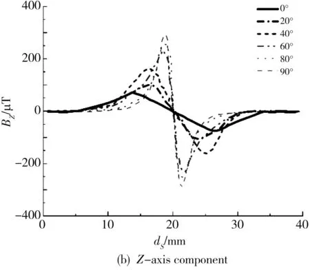
Fig.10 Variation of X-axis and Z-axis components of leakage magnetic field at different angles with scanning distance
3 Experiment and analysis
3.1 Establishment of experimental device
In order to verify the correctness of the theoretical model and the detection effect of the detection system, the magnetizer customized by a company is used as the experimental tool to detect and verify the defects in different extension directions. In this experiment, the experimental pipeline is a X50 steel pipe with Ф273×8 and a length of 10 m. At the bottom of the pipe, the defects of 20 mm in length, 2 mm in width and 4 mm in depth with the included angles of 0°, 20°, 40°, 60°, 80° and 90° with the axial direction are processed. For the magnetizer trolley, the axial and circumferential magnetization parts are separated by 300 mm. In the experiment of detecting cracks in different extension directions of the pipeline, the pipeline is first magnetized with a new type of magnetizer, and then the PNI sensor is used to collect the MFL signals of the circumferential and axial defects. The data acquisition unit USB-5 000 data acquisition card is responsible for the sensor acquisition. After preliminary processing, the MFL detection signal is converted into a digital signal that meets the requirements, and transmitted to the computer. The characteristics of the transmission signal of the data acquisition card are analyzed and extracted, and the relevant information of the defect leakage magnetic field in the tested steel plate is obtained, and the defect detection location and recognition is realized, as shown in Figs.11 and 12.
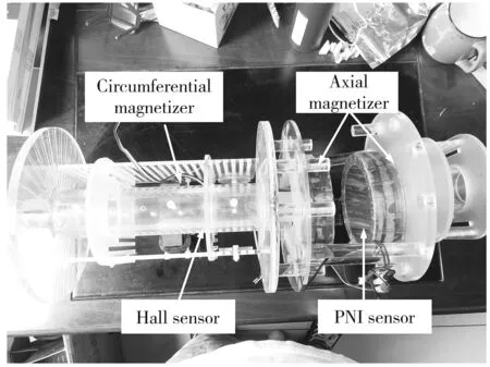
Fig.11 Magnetizer trolley
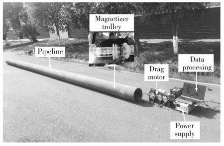
Fig.12 Field experiment platform
3.2 Effect of axial detection
In order to analyze the detection effect of the axial detector on the circumferential defect, a DC excitation current of 1 A is applied to the secondary coil, and the magnetizer model is driven by a motor to slowly scan through 6 cracks in different directions. As shown in Fig.13, theX-axis andZ-axis component signal changes of the leakage magnetic field at defects in different extension directions are analyzed.

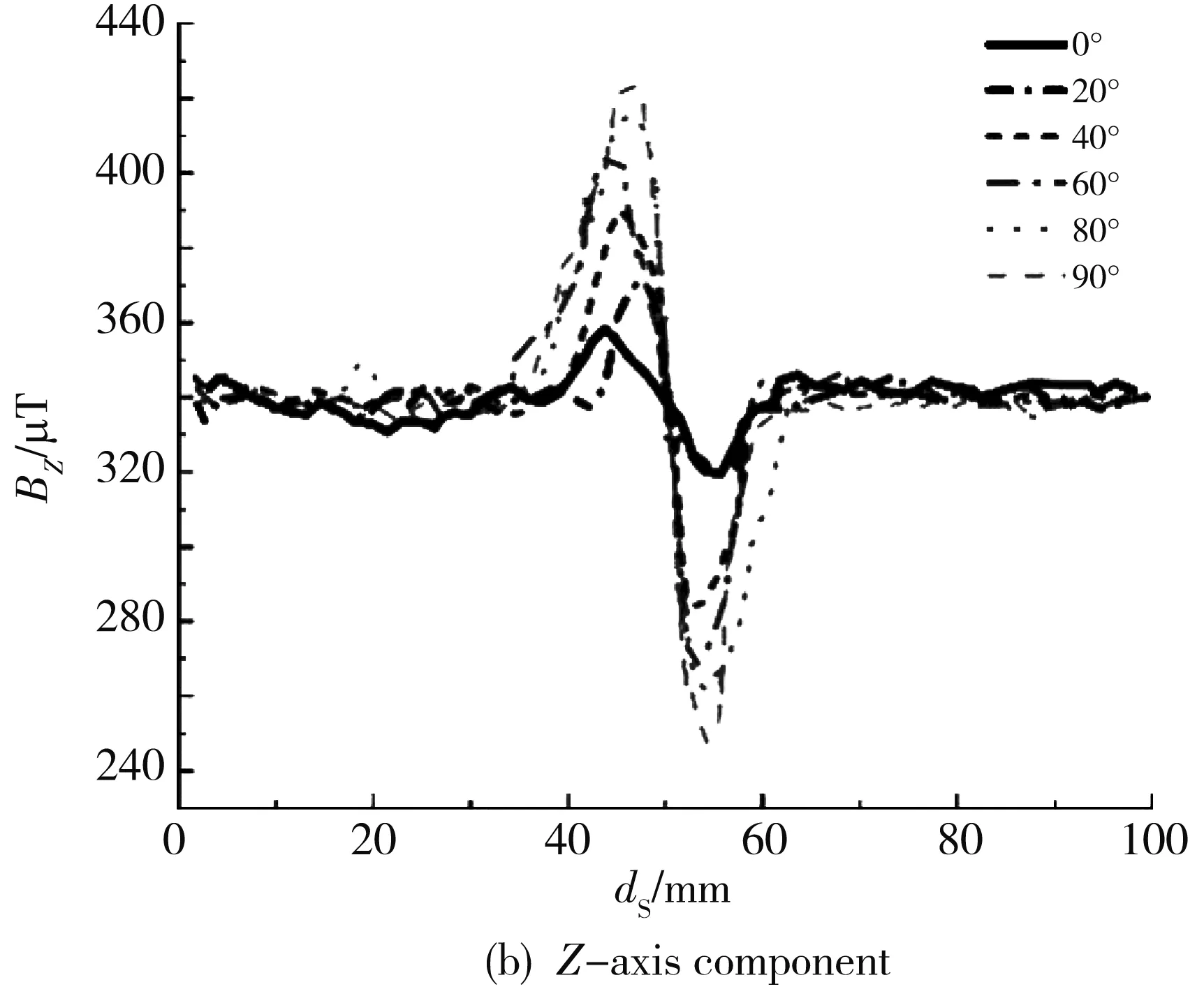
Fig.13 Magnetic flux leakage components of X and Z axes of axial detector at different angles with scanning distance
When the angle between the extension direction and the magnetization direction is less than 20°, theX-axis component of the leakage magnetic field is very small. When the included angle is greater than 20°, it increases obviously. When it exceeds 40°, the single peak characteristic is obvious, and the component curve is more concentrated and the amplitude is greater, indicating that the axial two-stage magnetizer has obvious characteristics ofX-axis detection component signals for circumferential extension defects or defects close to 90° extension direction. After the defect ofZ-axis detection component of axial detector exceeds 40°, the sinusoidal characteristics ofZ-axis component are more obvious, the amplitude is larger, and the waveform width is narrower, but the waveform concentration area begins to change to some extent.
3.3 Effect of circumferential detection
In the circumferential MFL detection, the MFL detection method introduced in section 1.3 is used to evaluate the defect MFL signal, that is, the “rate of change” of the leakage magnetic field is used as the detection object. Therefore, only need to collect the ΔUsignal, that is, the alternating current of the leakage magnetic field. During the experiment, the alternating excitation intensity must always be kept constant, that is, the effective value of the alternating excitation current ΔIis a fixed value, and a low-frequency and small-amplitude stable power supply is required, so the alternating signal source uses a low-frequency excitation signal of 5 Hz. The alternating current with a small amplitude is constant at 0.2 A. It can be seen from subsection 1.3 that the best measuring point is when the magnetic field is at the maximum in the magnetic field establishment stage. Therefore, in the experiment, set the DC bias currentIto change continuously from 0 A to 3 A at an interval of 0.1 A. The best working point is determined by observing the excitation currentIand leakage magnetic field detection signalUfor the defect leakage magnetic field with 90° extension direction.
The magnetization curve of the new magnetizer can be roughly divided into three stages: early stage, establishment stage and stable stage. In the early stage and stable stage, the change of excitation current is not sensitive, especially in the stable stage, the excitation flux in the magnetizer is in a nearly saturated state, the slope of the curve is close to stable or even close to zero, and the voltage fluctuation of leakage field also decreases. The best working point in the slope establishment stage in Fig.14 is the point with the largest slope. Therefore, it can be seen that it has the best detection effect under the magnetization condition of 0.6 A.
Therefore, 0.6 A is used as the excitation source of DC excitation, and the excitation intensity with alternating current of 0.2 A and frequency of 5 Hz are used for alternating excitation to detect the set 0°-90° defects.
As shown in Fig.15, with the decrease of the included angle of defects, the stronger the bimodal characteristics of the leakage magnetic field voltage difference curve, the greater the amplitude extreme value, the smaller the waveform width, the more concentrated the waveform, the larger the included angle, the smaller the waveform characteristics, and the leakage magnetic field presents a significant saddle shape when the included angle between the defect extension direction and the magnetization direction is less than 60°. It shows that the composite excitation circumferential magnetization method has a good effect on the defect detection with an angle of 0°-60°.
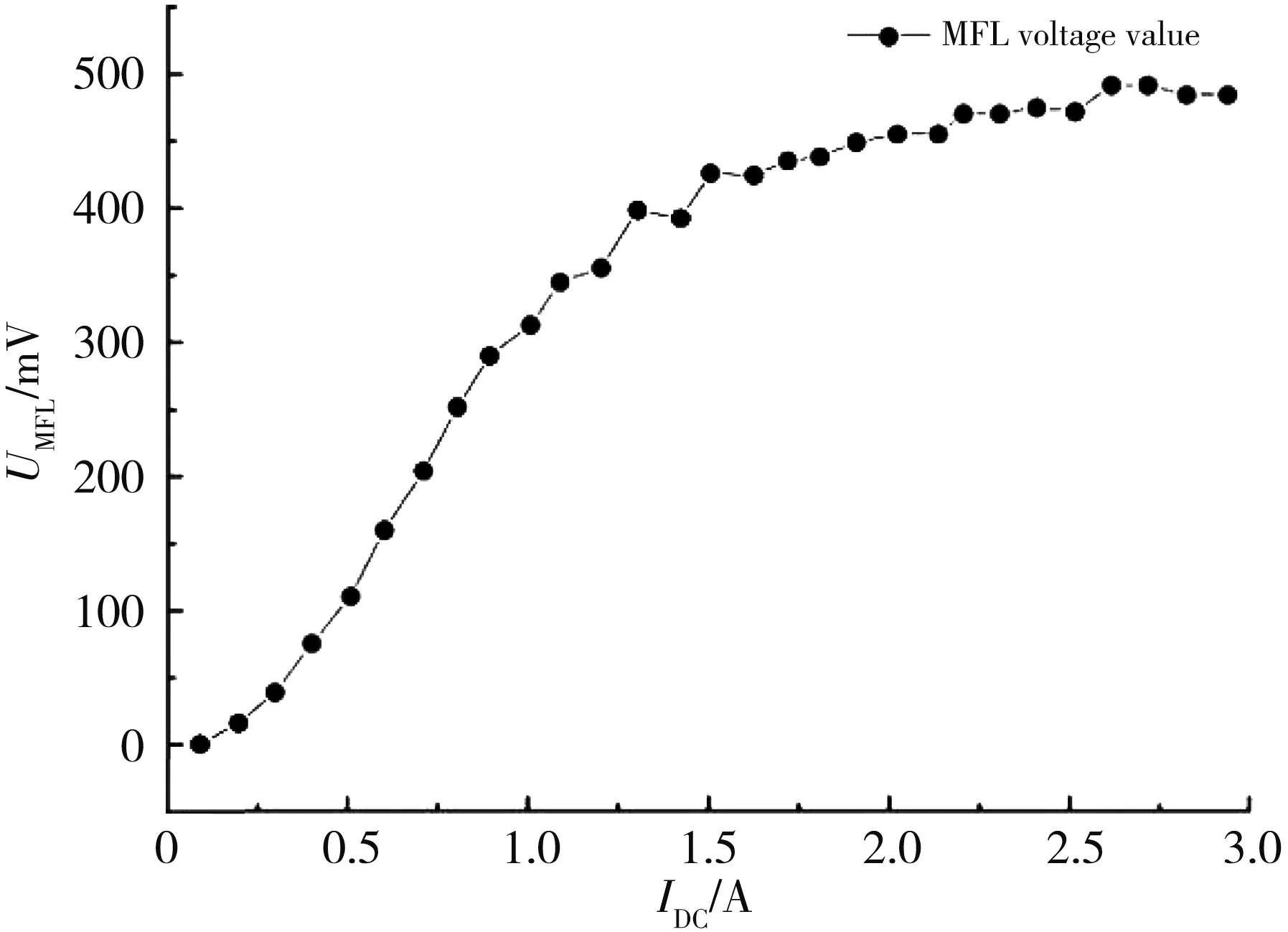
Fig.14 Peak value of X-axis leakage magnetic field component
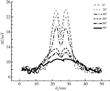
Fig.15 Leakage field voltage fluctuation ΔU
4 Conclusions
The method combining the circumferential direction and the axial direction is proposed in this paper, in which the method of measuring the voltage slope is used to indirectly detect the leakage field defect for the circumferential direction in the experiment. This experiment shows that the circumferential composite unsaturated magnetization can effectively reduce the volume and weight of the magnetizer, and the effect is better for defects with an angle of less than 60° between the direction of extension of the defect and the direction of magnetization, but it is less sensitive to defects above 60°, which is basically consistent with the theoretical and simulation results. The axial two-stage coil magnetization can establish a more uniform axial magnetization field. It is better for defects with an angle between the defect extension direction and the magnetization direction of more than 60°, but less sensitive to defects below 40°, which is basically consistent with the theoretical and simulation results. The experimental result shows that the new composite excitation multi-extension direction defect MFL detector can effectively detect the circumferential and axial groove defects of pipeline, which is consistent with the theoretical simulation analysis.
杂志排行

Journal of Measurement Science and Instrumentation的其它文章
- Bionic covert anti-reverberation active sonar detection method based on imitating whale whistles
- An effective method for performance evaluation of ACLS based on improved grey analytic hierarchy
- Comparative study of differential polarization imaging using linear and circular polarization in different scattering medium
- Dynamic path planning strategy based on improved RRT* algorithm
- Design of IP core based on AMBA bus
- MobileNet network optimization based on convolutional block attention module