Unmanned Aerial Vehicles: Control Methods and Future Challenges
2022-04-15ZongyuZuoCunjiaLiuQingLongHanandJiaweiSong
Zongyu Zuo,, Cunjia Liu,, Qing-Long Han,, and Jiawei Song
Abstract—With the rapid development of computer technology,automatic control technology and communication technology,research on unmanned aerial vehicles (UAVs) has attracted extensive attention from all over the world during the last decades. Particularly due to the demand of various civil applications, the conceptual design of UAV and autonomous flight control technology have been promoted and developed mutually.This paper is devoted to providing a brief review of the UAV control issues, including motion equations, various classical and advanced control approaches. The basic ideas, applicable conditions, advantages and disadvantages of these control approaches are illustrated and discussed. Some challenging topics and future research directions are raised.
I. INTRODUCTION
AN unmanned aerial vehicle (UAV) (or unpiloted aerial vehicle) is commonly known as an aircraft without a human pilot onboard that can fly autonomously. It is the powered aerial vehicle that uses aerodynamics and propulsion to provide vehicle lift and control forces. Compared with crewed aircraft, UAVs were originally used for missions usually dull, dirty or dangerous for humans or cases where the small size of the aircraft restrict the presence of a pilot.Although initially reviewed as military devices, UAVs rapidly find more civil applications including aerial photography,payload deliveries, smart agriculture, surveillance, infrastructure inspections, and drone racing, to name a few.
UAVs can be usually categorized into two main classes:fixed-wing UAVs and rotorcraft UAVs. The fixed-wing UAV requires relative velocity for the production of aerodynamic forces, thus is more aerodynamically efficient, but may need a runway for take-off and landing. The rotorcraft UAV uses rotary wings to produce the thrust force for motion [1], which leads to the vertical take-off and landing (VTOL) capability.The combination of fixed-wing and VTOL features motivates to many hybrid UAV configurations, which become prevalent in recent years [2]. Correspondingly, the control design for different kinds of UAVs also varies.
This survey is written in a control-oriented fashion. On the one hand, the survey introduces basic elements in flight control design. On the other hand, the survey may serve as a catalogue of control design methods for researchers and practitioners in the community.
II. MAIN ISSUES IN CONTROL
The development of various new types of UAVs created a great need for autopilot systems. However, to achieve multimission and high flight quality of aircraft, it is very challenging for flight control system design. These issues include, but are not limited to:
• In essence, classical control design relies heavily on the understanding of the physics of flight and provides a designer with clues to see how the dynamic performance is modified.Although classical control theory relates very closely to the physics of the control problem, it is difficult to handle the coupling multiple loops design task [3]. In other words, the classical one-loop-at-a-time design does not guarantee success when more loops are added and coupled.
• In contrast to classical techniques, modern control techniques (e.g., eigenstructure assignment techniques [4],dynamic inversion [5]) provide a systematic way to design multi-loop controllers by closing all the feedback loops simultaneously and yield the desired performance. However,these model control techniques usually require the exact knowledge of aircraft models and are sensitive to modeling errors and external disturbances. Unfortunately, the exact model of aircraft like helicopters is difficult to obtain,especially aerodynamic parameters, which prohibits the practicality of modern control techniques.
• There exists an increasing interest in adaptive control of aircraft. The progress in systems theory leads to fundamental theory for the development of stable adaptive control architectures [6]. The available adaptive flight control algorithms, however, are unable to guarantee the closed-loop robustness because the bandwidth of the closed-loop system cannot be prescribed [7]. In addition, the system output has overly poor transient tracking behaviour before the ideal asymptotic convergence is achieved [8]. Thus, robustness and stability issues of adaptive flight controllers need to be considered simultaneously in design [9].
• Disturbances and uncertainties are the factors which may cause the unsatisfactory performance. It is very important to design flight controllers accounting for disturbances, such as wind gusts, sensor measurement noise, and modeling errors.The modern robust design techniques (e.g.,H∞design [10])provide performance robustness which is the ability to ensure satisfactory performance even if the aircraft may be subject to disturbances. However, it is usually difficult to obtain the upper-bounds of various disturbances and a controller with the desired structure.
III. KINEMATICS AND DYNAMICS OF AIRCRAFT MOTION
A. Coordinate Systems
In studying unmanned aircraft systems, it is important to understand how an aircraft is oriented with respect to the earth. It is necessary to use several different coordinate systems to describe the position and the orientation of the aircraft in an easy manner. The coordinate systems of interest include an earth-fixed frame, a body-fixed frame, a wind frame, and a flight-path coordinate frame, as shown in Fig. 1.
Definition 1:Frame E={OExEyEzE} denotes an earthsurface inertial frame with its originOEat the defined home location,xEaxis positive in the direction of north,yEaxis positive in the direction of east andzEaxis down. This coordination system is also known as a north-east-down(NED) reference frame.
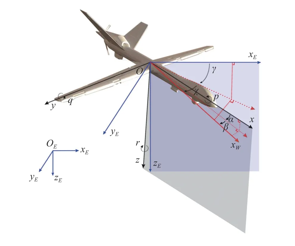
Fig. 1. Coordinate systems.
Definition 2:Frame B={Oxyz} denotes an aircraft-body frame with its originOat the center of mass of an aircraft,xaxis positive out the nose of the airframe,yaxis positive out the right wing andzaxis positive below the aircraft.
Definition 3:Frame W={OxWyWzW} denotes a wind frame with its originOat the center of mass of an aircraft,xWaxis positive in the direction of the velocity vector of the aircraft relative to the air, i.e. the airspeed vector,zWaxis positive below the aircraft in the plane of symmetry of the aircraft,yWpositive determined by the right hand rule, i.e. to the right.
Definition 4:Frame P={OxPyPzP} denotes a flight-path coordinate frame with its originOat the center of mass of the aircraft,xPaxis positive in the direction of the velocity vector of the aircraft relative to the ground, i.e. the ground vector,zPaxis positive below the aircraft in the plane of symmetry of the aircraft,yPpositive determined by the right hand rule.
Remark 1:Note that if wind is not taken into account, the frame P coincides with the frame W. In flight control system design, wind is regarded as an external disturbance rather than a system state. In what follows, the kinematic and dynamic equations are established in the absence of wind.
Remark 2:The earth-surface inertial frame is convenient to express translational kinematics. The aircraft-body frame is especially convenient in the sense that the inertial parameters and the force of thrust remain fixed. The wind frame facilitates the expressions of the aerodynamic forces and moments acting on an aircraft.
In addition to defining the coordinate systems, the relative orientation of these frames can be determined and expressed in various forms, such as rotation matrices, Euler angles, unit quaternions. In particular, various Euler angles relating to these coordinate systems are important to the flight dynamics of UAVs. In flight dynamics, roll, pitch, and yaw Euler angles(i.e.,φ,θ, andψ, respectively) are commonly used to parameterize the rotation from the frame E to the frame B,while the sideslip angleβand the angle of attackαare commonly used to perform the transformation from the frame W to the frame B. Analogously, to obtain the frame W from the frame E, a set of Euler angles, namely, the heading angleχ, the flight-path angleγ, and the bank angleμare frequently utilized.
B. Kinematic Equations
The kinematics of a UAV includes the translational and the rotational equation of motion. The following assumption is usually made in the existing literature in developing navigation, guidance, and control strategies for UAVs [11],[12].
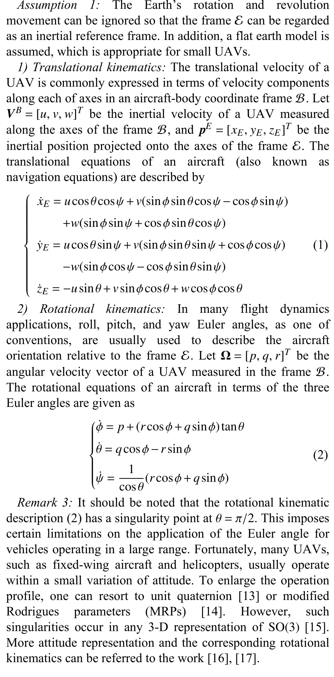
C. Dynamic Equations
A variety of dynamic models for UAVs appear in the literature. Basically, the equations of motion are derived by implementing Newton-Euler formulas that deal with vector summations of all forces and moments applied to the aircraft relative to a reference frame. However, for practical control system design problems, it is very subtle to select appropriate frames and establish the motion model of UAVs. One should take into consideration simultaneously the characteristics of a specific aircraft, navigation accuracy, performance specifications and/or a control algorithm. In what follows,several commonly used motion models based on Newton-Euler law are introduced.
Assumption 2:An aircraft can be viewed as a rigid body with constant mass. The geometric shape and internal mass distribution of the aircraft are symmetrical with respect to the vertical planeOxz, i.e., the product of inertiaIxy=Izy=0.
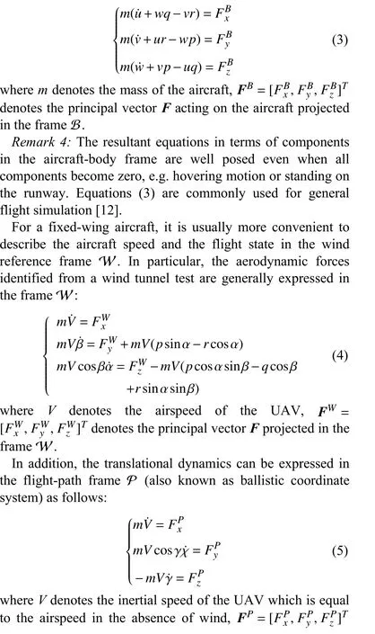
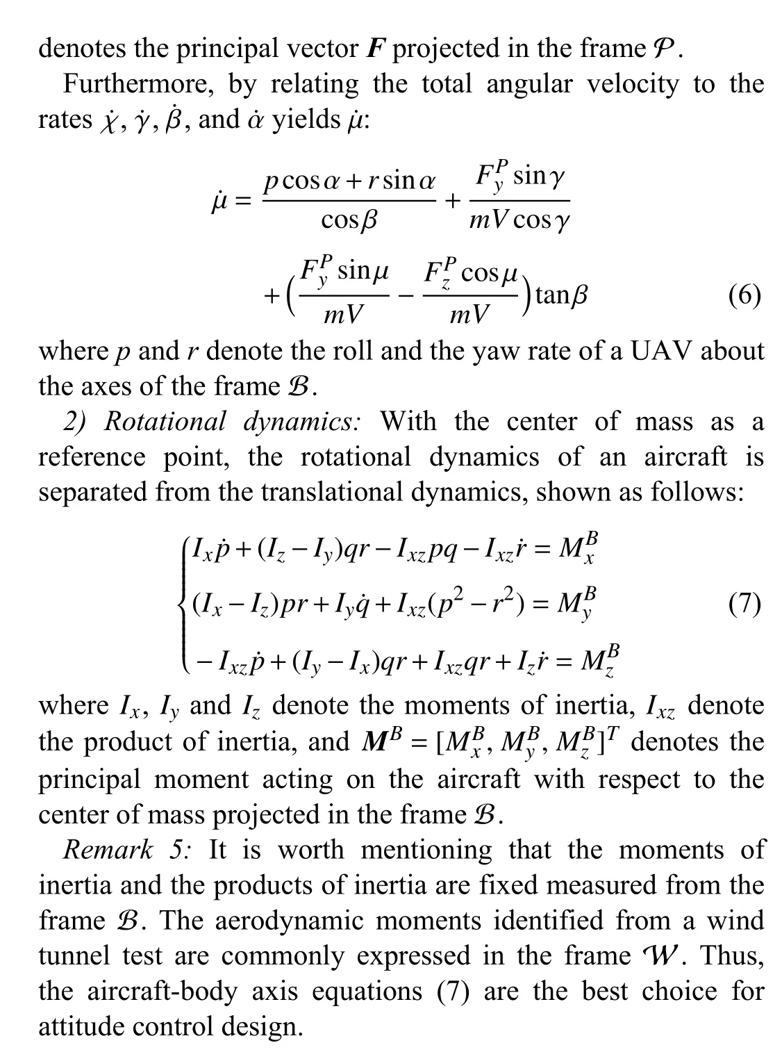
1) Translational dynamics:The translational equations are straightforward by applying Newton’s second law, and the acceleration of an aircraft is derived from the vector summation of various forces. In terms of motion relative to the Earth, the translational equations written in the frameB introduce the Coriolis and centripetal terms, shown as follows:
D. Summary
The motion equations derived in this section are established based on the basic kinematic and dynamic laws. However,they can be written in different forms or different reference frames. To analyze and design a flight control system based on a control-oriented model of a UAV, it is essential to choose appropriate coordinate systems to define and describe the relevant motion parameters. For instance, unmanned rotorcraft UAVs (e.g., helicopter, quadrotor) are very suitable for quasistatic flight with small attitudes [18]. Thus, it is preferable to use aircraft-body equations (3) and (7) for control and simulation [19]–[21]. However, for super-manoeuvrable aircraft, it is required to hold sideslip angle near zero in order to improve the manoeuvrability and reduce the impact of heat flow at high speed [22]. It is justified to select the angle of attack, sideslip angle and bank angle for motion control.Besides, as shown in [23], [24], the motion of a symmetric UAV (especially missile) about its velocity vector can be alternatively described by using body axis accelerations instead of forces. The dynamic equations for the body axis accelerations at the center of mass are given by
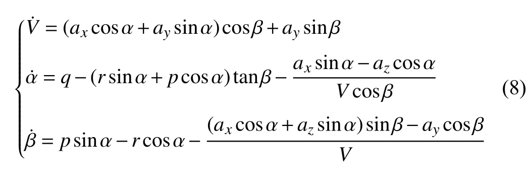
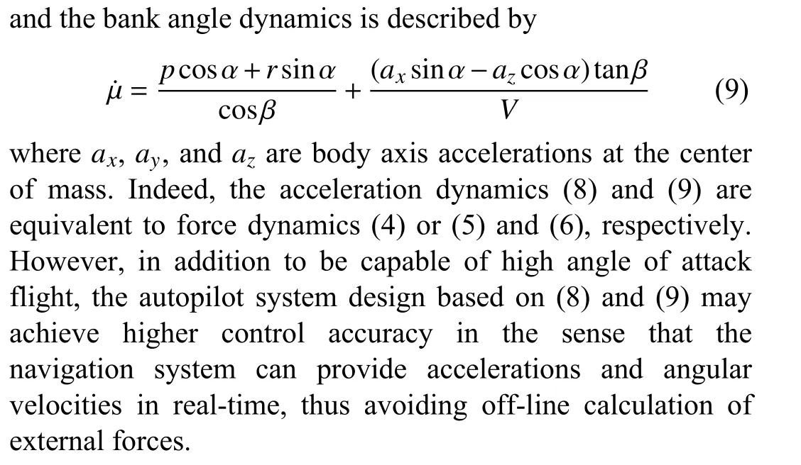
In brief, motion equations for UAVs can be various. One should balance the ease of representation of variables and control tasks of specific aircraft.
IV. FLIGHT CONTROL METHODS
This section gives a survey of commonly used flight control methods for UAVs, including classical control methods and advanced control designs based on exact models or uncertain models. Table I lists a summary of these methods.Specifically, linear/linearized or exact nonlinear model based control designs are classified into the category of classical control, while advanced control concerns about perturbed or uncertain model in this survey.
A. Classical Control
In Section III, several motion equations are given based on different representations or reference frames. Without loss of generality, the aircraft model can be formulated as the following affine nonlinear system:
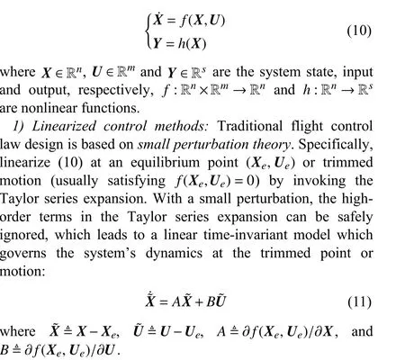

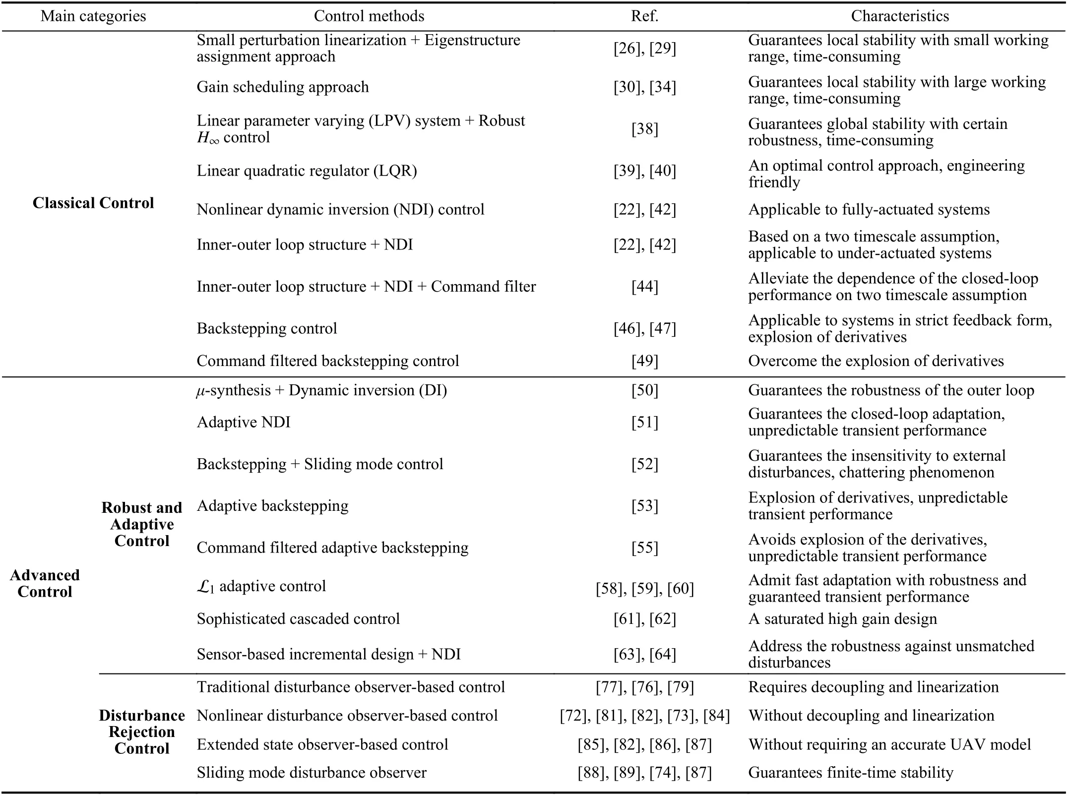
TABLE I CONTROL METHODS FOR UAVS
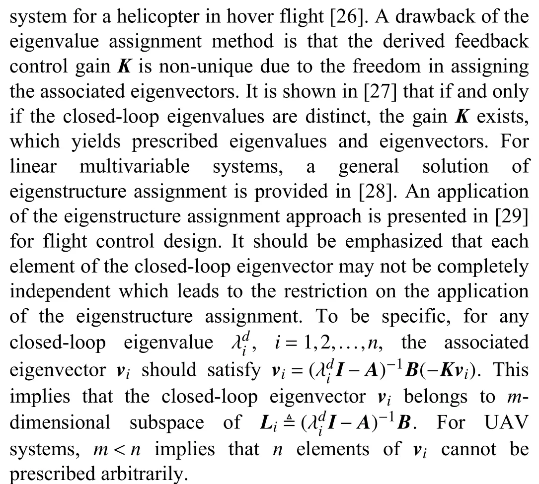
These classical synthesis methods are able to achieve satisfactory performance only in a small range of trimmed point where the linearized model (11) works. For a large flight envelope, the closed-loop performance may deteriorate significantly and even the closed-loop stability cannot be guaranteed. Gain scheduling [30] was once widely used in flight control systems, which involves interpolating the linear control law design at intermediate operating conditions. Based on the monitored operating condition, the gains in the linear controller are scheduled accordingly. The principles for gain scheduling include gain interpolation, neural network [31],genetic algorithm [32], and fuzzy logic [33]. Take the work[34] for instance, a fuzzy gain scheduled controller is presented for an unmanned helicopter to achieve attitude stabilization within large ranges. Two prominent gain scheduling guidelines [35] can be raised: i) the scheduling variable should capture the plant’s nonlinearities and ii) the scheduling variable should vary slowly. Hence, gain scheduling methodology cannot indeed guarantee global stability and robustness.
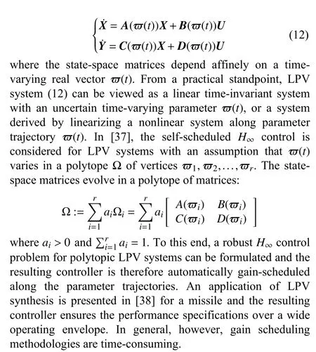
To remove these limitations due to gain scheduling, a theory for linear parameter varying (LPV) systems [36] is developed.The state space description of an LPV system can be written as follows:
Linear quadratic regulator (LQR) reduces the amount of work done by control engineers to optimize a controller. In early flight control system designs, LQR is commonly used and its successful applications include F-8C and X-29 prototypes. Essentially, LQR is an optimal control approach with a cost function described by a quadratic form. In [39], an application of LQR for the missile guidance is shown and the flight test results are also provided. In [40], a normal LQR controller is developed for a helicopter to achieve hovering flight, which combines an active model enhancement technique by means of the unscented-Kalman-filter (UKF)estimation.
2) Nonlinear control methods:It is shown in Section III that the motion equations of an aircraft present a highly nonlinear and coupling dynamics. Linearized model-based synthesis techniques encounter difficulties in guaranteeing stability and robustness in a full flight envelope. In addition to the performance limitation, flight missions achieved by classical control are relatively simple. As a result, for modern UAVs,nonlinear control techniques are more appealing and competitive in improving flight performance and reducing workload for flight engineers.
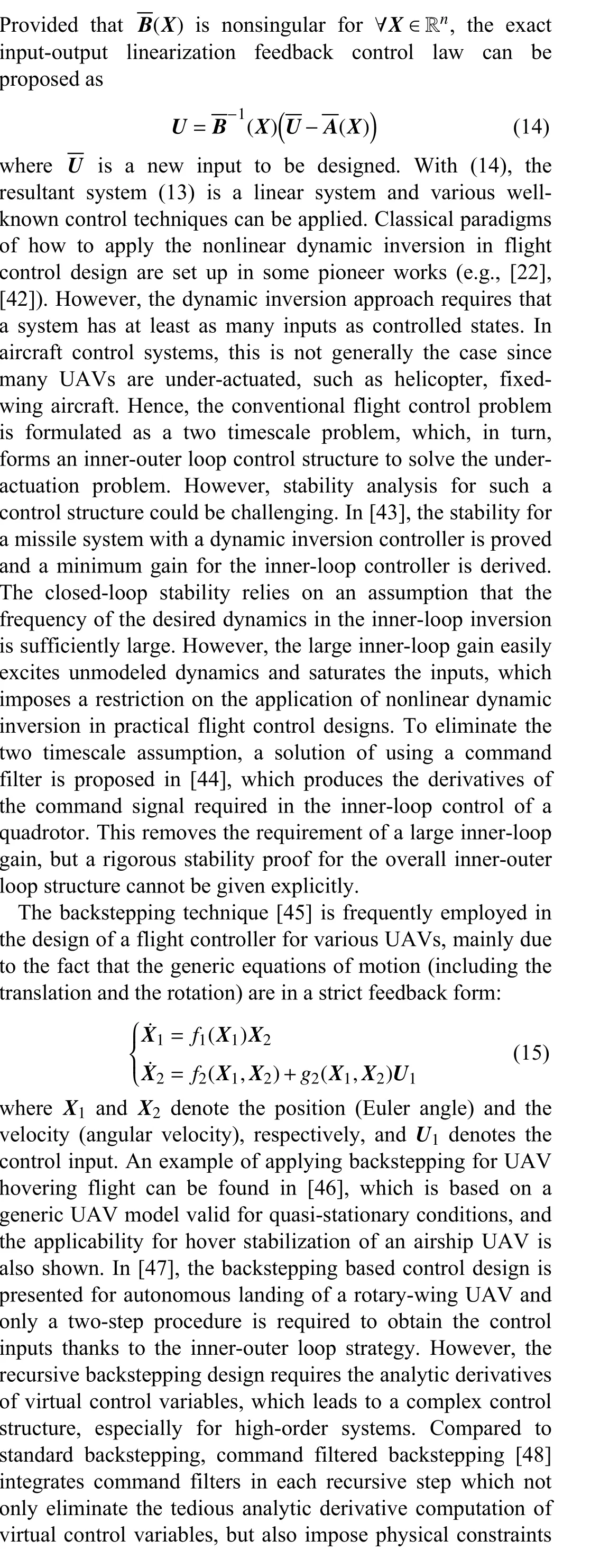
Linearization feedback or nonlinear dynamic inversion [41]technique provides a straightforward means of deriving control laws for nonlinear systems. In particular, the unwanted terms in the equations of motion are cancelled by the input using negative feedback of these terms. For example, given a set of outputsY=[y1,y2,···,ys]Tand their relative degrees are denoted byri,i=1,2,...,s, respectively, by successive differentiation, one obtains

B. Robust and Adaptive Control
The exact model-based control techniques discussed in Subsection IV-A are usually very sensitive to any variation of model parameters, thus lacking robustness and adaptation. In particular, exact dynamics of an aerial vehicle can hardly be established and some external disturbances cannot be measured either. This requires the development of more advanced control methodologies to handle model uncertainties as well as unknown disturbances.
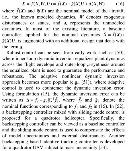
To account for system uncertainties and exogenous disturbances, the state-space equation of the aircraft can be rewritten as
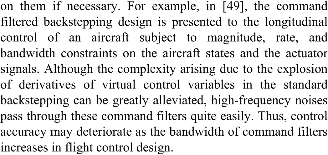
Similar to standard backstepping, the adaptive version also suffers from the problem of the explosion of complexity arising from the differentiation of intermediate virtual control.Command filtered adaptive backstepping [54] provides an implementation approach for adaptive backstepping control by introducing filters to generate compensating signals for adaptive parameter estimation. In [55], the command filtered adaptive backstepping design is presented to solve the trajectory tracking problem for a quadrotor with unknown a erodynamic drag coefficients and external disturbances. Note that the adaptation rate relates closely to the closed-loop performance and stability. In other words, the closed-loop transient performance is unpredictable and the high adaptation rate will deteriorate the closed-loop stability [56]. Notably,L1adaptive control theory [57] allows for fast adaptation with guaranteed robustness. The key properties of L1adaptive controller are validated in several benchmark flight tests as shown in [58], [59]. In particular, the L1adaptive backstepping design is presented for the translational dynamics of a multirotor UAV, using a piecewise constant adaptation law to estimate the lumped unknown term Δ in the presence of fast adaptation [60].
Robust controllers are also designed for VTOL UAVs. In[61], a sophisticated cascaded control structure is developed for a small helicopter by combining feed-forward control actions and high-gain controller with nested saturation function. It is proved in the experiments that the control design is able to robustly track the trajectory tracking with respect to various system uncertainties. A similar design approach is also applied to a ducted-fan UAV with solid experimental results [62].
Another interesting control design paradigm is the sensorbased incremental design combined with NDI [63] or other alternatives. It uses sensor measurements to replace part of the system model information when dealing with model mismatch uncertainties. This control scheme is demonstrated in flight tests with promising results [64]. It should be noted that there are many other control approaches also incorporating an observer to improve the robustness and control performance[65], [66].
C. Disturbance Rejection Control
Disturbance rejection control aims to actively compensate or attenuate the influence of external disturbances acting on the UAV dynamics, so as to improve the flight performance.The basic principle of disturbance rejection control is first to design an observer to estimate the lumped disturbance term Δ,as in (16), and then to exploit such an estimate Δˆ in control design to eliminate its influences. There are several observer design that can be applied for UAV fight control, including disturbance observers [67], extended state observers [68] and sliding mode observers [69], [70]. A comprehensive review on disturbance rejection control can be found in [71], with a focus on disturbance observer based control techniques.
As indicated in [71], the disturbance observer based design paradigm exhibits several advantages when it is applied to UAV flight control design. Such a technique can be regarded as a “patch” function to the existing flight controllers, which offers flexibility in control integration. In terms of UAV control, disturbance observer based control is integrated with nonlinear dynamic inversion [72], backstepping [73], sliding mode control [74], [75], andH∞[76], [77]. Another feature of disturbance observer based control is the capability of recovering the nominal control performance. The baseline feedback controller can focus on delivering the tracking performance and stability, while the disturbance rejection and robustness against uncertainties can be left to the compensation loop. This means in the absence of disturbances/uncertainties, the nominal control performance of a UAV thus can be retained.
A traditional disturbance observer in the frequency domain is proposed [78], which has two key steps: the inverse of a nominal plant model and the design of a low pass filter. Since this disturbance observer is mainly designed for single-inputsingle-output linear time-invariant systems, it is usually used to deal with decoupled and linearized dynamics of a UAV. In[77], linearized models around the hovering condition of a tail-sitter are obtained via a frequency sweep method and used in disturbance observer design. Similarly, in [76], a disturbance observer is applied to inner loop control of a quadrotor, but the nominal model used in disturbance observer design is an error dynamics obtained through feedback linearization. It should be noted that theH∞synthesis is employed to balance the robustness and the disturbance rejection performance [78], [76]. For more complicated UAV systems, such as a fully actuated thruster-tilting multicopter[79], a more sophisticated decoupling and simplification process will be required.
Compared to the disturbance observer in the frequency domain, a more flexible and effective formulation is a nonlinear disturbance observer proposed in [80]. This design allows the nonlinear model to be directly exploited in control design rather than being treated as disturbances, which also means that decoupling and linearization may not be necessary in flight control design. Such a scheme is deployed on a small helicopter to perform an accurate pirouette maneuver by addressing the coupling effect between the lateral and longitudinal dynamics [72] and on a quadrotor to improve the tracking performance under the ground effect [81]. Some variations of this disturbance observer structure have been developed in recent years to deal with many other difficulties.One direction is to incorporate a more comprehensive model to represent different types of disturbances. For example,exogenous disturbances, which include periodic disturbances caused by a slung payload or composed with different frequency harmonics, are addressed in [82] and [83],respectively. It should be noted that the original nonlinear disturbance observer design is a reduced-order observer,which means that all the system states should be available to the observer. Since the onboard sensors may be limited to small UAVs, the nonlinear disturbance observer has been extended to deal with partially measurable system states,which are often raised from actuator dynamics of the UAV.Examples include the disturbance observer design to accommodate unmeasurable flapping dynamics of an unmanned helicopter [73] and unknown actuator states of the control surfaces on a fixed-wing UAV [84].
Another popular disturbance rejection approach is based on an extended state observer (ESO). The traditional ESO design does not require a specific model of the system. Instead, the system dynamics needs to be cast into a chain of integrators based on the relative degrees [68]. This may be convenient in practice since it is not always easy to obtain an accurate UAV model. However, abandoning the knowledge of a system model may induce high frequency fluctuations in the control signal, especially when the system order is high. Therefore,ESO based controllers are normally used for low-order subsystems such as individual attitude/translational dynamics in the cascaded control structure to replace traditional PID controllers [85]. More recent design techniques such as feedback linearization are used to derive the linear models of quadrotors for ESO design [82], [86]), where the model information is partially incorporated. The nonlinear ESO design for quadrotors using a detailed angular velocity model is presented in [87] with promising experimental results against wind gusts.
A sliding mode disturbance observer is a powerful tool in flight control design. It does not rely on the complete knowledge of the disturbance model. Instead, with just information of disturbance bounds, the simple low-order observer design can be realized, which can also estimate the derivatives of disturbances. This feature is very useful as most of the disturbances on UAVs are difficult to model. After initially demonstrated on a reusable launch vehicle [88], an sliding mode disturbance observer is used on quadrotors [89],[74] and fixed-wing UAVs [87] for various applications. The sliding mode disturbance observer design also offers a framework to establish theoretical properties such as finitetime stability and incorporate high-order disturbance models.However, the benefit of using the high-order disturbance model still requires further evidence from flight tests, as most of the relevant studies still rely on numerical simulations.
V. TASK SPECIFIC CONTROL DESIGN
The ultimate goal of flight control design is to enable UAVs to perform specific tasks automatically. Some task requirements can be formulated or converted to a standard control problem, thus can be solved by using above mentioned control methods. The most common UAV tasks would be trajectory tracking and path following functions, which usually serve as the basis of more complicated flight missions,such as formation flight and drone racing. The main solution depends on the definition of a trajectory- or path-dependent error space to express the dynamic model of a UAV in such tasks. Then, various standard control methods can be applied to solve the trajectory tracking or path-following problem,such as gain scheduling [90], feedback linearization [91],sliding mode control [92], L1adaptive control [58].
A. Trajectory Tracking Problem

Trajectory tracking problems are concerned with controller design that force a vehicle to reach and follow a geometric path with an associated timing law. In this sense, the trajectory tracking based control system design is quite suitable for high maneuverability [93] and time-critical missions [94].
To solve the trajectory tracking problem, the difficulty highly relies on the configuration of an aircraft. For fullyactuated systems, the trajectory tracking problem has been well understood. However, many UAVs, including spacecraft,aircraft, helicopters and missiles, are typical under-actuated systems. The trajectory tracking problem for under-actuated UAVs is especially challenging because these systems are in general not fully feedback linearizable, and therefore standard tools, such as feedback linearization and backstepping, are not straightforwardly applicable [95].
The classical trajectory tracking control of under-actuated systems uses decoupling of a multi-variable model to steer the same number of degrees of freedom as the number of available control inputs. Taking a helicopter for example, it is common to separate the control problem into an inner-loop that stabilizes the attitudes and an outer-loop that controls the trajectories of the vehicle [96]. It should be emphasized that the desired trajectory does not need to be a trimming one and can be any sufficiently smooth bounded curve parameterized by time. This provides UAVs with more flexible task-oriented control design.
B. Path-Following Problem
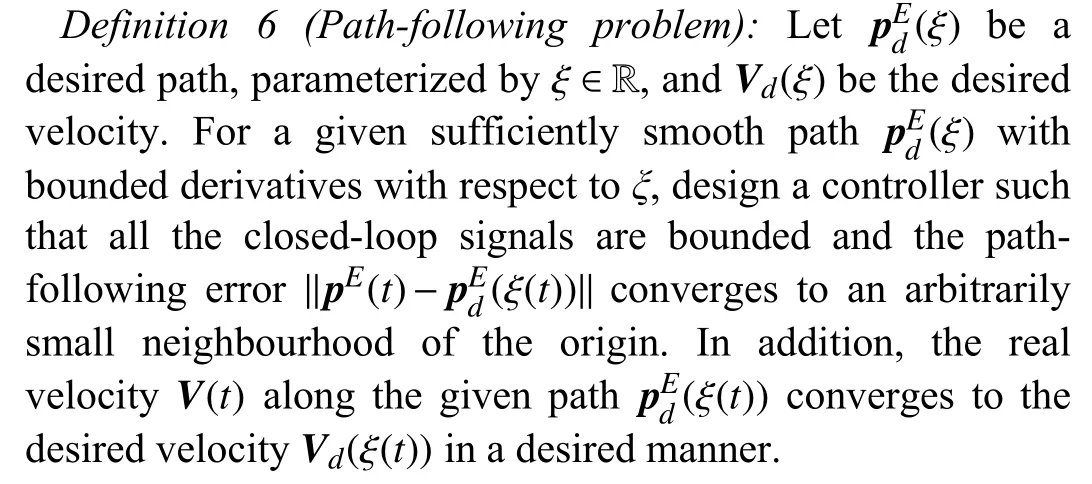
Different from the trajectory tracking control problem, the path-following control problem is decoupled into a geometric path-following problem and a speed-assignment problem. The geometric task is to stabilize a family of trajectories with the same geometric pattern but with diversely admissible speed profiles, called path following manifold [91], [98]. The remaining speed assignment, which is usually given as a timing law, determines the diversity. In some non-minimum phase systems, the timing law for ξ(t) can be well designed to stabilize the unstable zero dynamics [97]. Due to the extra timing law ξ˙(t), path-following control is more flexible than trajectory tracking control. In this sense, path-following control is quite suitable for some UAVs with physical speed restrictions, such as fixed-wing UAVs [99], [100], rotary-wing UAVs [101] and airships [102], [103], and for some specific missions without temporal requirements.
One of the typical missions is target tracking which covers many military applications, such as adversarial target observation and friendly convoy protection. In [104], a visionbased target tracking guidance algorithm is proposed with an image motion estimation system. The guidance law prescribes the UAV flying perpendicular to the line of sight vector and regulates the speed to maintain a constant range between two vehicles. Lyapunov guidance vector fields are developed for autonomous coordination of multiple unmanned aircraft [105],which yields feasible and globally stable paths with guaranteed target stand-off distance bounds. The loitering tracking strategy is further improved and extended in [106]and [107] by speeding the convergence process and imposing a curvature limitation, respectively.
VI. FUTURE CHALLENGES AND RESEARCH DIRECTIONS
As the principles of UAV flight control have been well understood over last two decades, commercial efforts and open-source community have delivered a good level of maturity for flying common UAV platforms in open space.The growth in technology readiness and reliability of UAVs has fueled the interest in deploying UAV platforms in wider and more challenging scenarios, which, in turn, poses higher requirements on flight control system design.
A. Challenging Issues
Loosely speaking, many of the remaining technical challenges may arise from two aspects, i.e., unknown/uncertain dynamics and external operating environments.
•Unknown/uncertain dynamics: Some UAV platforms,especially those with unconventional configurations, such as over-actuated multirotors [108], hybrid UAVs [109] and bioinspired UAVs [110], may suffer from complex and poorly unknown dynamics. The same issue may also be encountered when pushing UAVs to their dynamics limits, such as in drone racing and operating under partial faults. Another example is aerial transportation, including suspending the payload [111]or grasping the payload [112], where the influence of the payload could be difficult to capture. In such situations,traditional modeling means, such as wind tunnel testing and system identification may be too expensive to run or inadequate to provide satisfactory results within a desired time frame.
•Unknown/uncertain external operating environments:Many applications may require UAVs to be operated in an unknown, or partially known environment, which could be dynamically changing at the same time. Such an application may also include UAVs flying in close proximity to objects in the environment (e.g., for infrastructure inspection) or having physical interactions with the environment (e.g., aerial manipulators). The flight control design thus needs to take into account the performance or imperfection of the sensing and perception systems in a more systematical way.
It should be noted that the technical challenges from those two areas are often coupled. Physical interactions with operational environments usually exert external forces and moments on UAV dynamics, which are difficult to capture or model. Flying in unknown and dynamic environments may require the UAVs to take aggressive manoeuvres to avoid obstacles that can only be detected in a close range. To this end, the design and implementation of sophisticated control techniques that can work in conjunction with advanced estimation and perception algorithms would be a focal point of future research on UAV flight control.
B. Continuing Research
In recognition of those challenges in UAV flight control design, there are a number of emergency control design methods that have already shown the potential for addressing some of the issues.
Traditional control design methods to a large extent leverage the knowledge of the system dynamics in the form of a system model but could be less effective when incorporating knowledge of or influence from external environments (which are often regarded simply as disturbances or uncertainties). To this end,learning-based controlmethods, also known asintelligent control, may offer an alternative way of dealing with unknown dynamics [113], challenging environments[114] and even intelligent actuators [115] involved in UAV operations. Note in recent years that the confluence of big data and machine learning is steering a paradigm shift in the analysis and understanding of dynamical systems in UAV engineering. One of the most noteworthy is the so-called Koopman operator theory [116] which opens a path to identify intrinsic coordinate systems to represent nonlinear dynamics in a linear framework. It could be expected that obtaining linear representations of strongly nonlinear systems has the potential to revolutionize our ability to predict and control complex UAV systems in large-scale and dynamic changing environments [117]. Hence, the integration of data driven and learning based techniques with dynamical systems theory opens up a new opportunity to tackle previously unattainable challenge problems in modeling and control of UAVs without detailed system knowledge.
Control with safety guaranteesfor UAVs is another important area to be investigated, and there are several daunting technical problems to tackle especially when UAVs are making their way into civilian applications. New control technologies must be safe and reliable enough for the general public to have confidence that nothing will go wrong. Control design with constraints in mind, such as using a barrier Lyapunov function [118], would be a useful solution to realize the position constrained trajectory for UAVs deployed in confined areas. In addition, the UAV operation in close proximity to structures and the terrain is more difficult when navigation information is not fully available (e.g., GPS dropouts) and collision avoidance is obligatory. This requires an integrated control system in terms of perception [119], state estimation [120], and obstacle avoidance algorithms [121]. It is even more challenging when navigating multiple UAVs safely and efficiently in a large-scale airspace with both static and dynamic obstacles under wind disturbances. Data-driven based control methods (e.g., [122]) may have a great potential to enable safe and efficient UAV operations in a large-scale dynamic civilian environment. However, accidents may happen when the training data is noisy or the training process does not fit the real-world scenarios [123] and rigorous stability proof is usually unaccessible [124]. To this end,continuing research is required to establish more formal verification and validation frameworks to guarantee the safety of emerging control methods for UAVs.
VII. CONCLUDING REMARKS
As discussed in this survey, established model-based flight control methods have made a great success in delivering automatic flight functions for different types of UAVs. The maturity of basic flight control has in turn increased people’s expectation of using them in more public domains and civilian airspace. On one hand, UAVs can offer enormous potential for applications in urban environment, ranging from infrastructure monitoring to traffic surveillance, emergency response and medical payload delivery. On the other hand, the complexity and diversity of the tasks and the uncertainties in the operation environments have posed more challenges on the autonomy, intelligence and safety features of UAV systems, which may be beyond the reach of existing modelbased flight control methods.
Recent advances in machine learning and data-driven methods, as well as emerging sensing and perception capabilities from robotics, show a promising technical pathway to build more autonomous and intelligent UAV systems by allowing them to learn from experience and perceive the environment. The combination of advanced sensing modalities and learning based algorithms for flight control design creates a series of technical, theoretical and safety challenges:
• Comprehensive frameworks, either through theoretical analysis or using numerical verification, need to be established to examine the system stability of the UAV when large level of uncertainties are introduced by advanced perception systems.
• New methodologies are required to verify and analyze the learning based algorithms beyond basic flight stability analysis, because real-world situations may breach the scenarios or datasets used in the training process.
• Suitable specifications for assessing the functionality of UAVs need to be developed to ensure safety and reliability in response to the diversity of the tasks in dynamic and unpredictable urban environment.
• Ethical and legal issues in relation to responsibility and liability of UAV operations should also be considered when designing more autonomous and intelligent functions.
To enable deployment of UAVs in civilian airspace, these grand challenges need to be addressed jointly by the UAV research and development community, but it is envisaged that a wider and profound impact will then be delivered on the society.
杂志排行
IEEE/CAA Journal of Automatica Sinica的其它文章
- Energy Theft Detection in Smart Grids: Taxonomy,Comparative Analysis, Challenges, and Future Research Directions
- On the System Performance of Mobile Edge Computing in an Uplink NOMA WSN With a Multiantenna Access Point Over Nakagami-m Fading
- Continuous-Time Prediction of Industrial Paste Thickener System With Differential ODE-Net
- A Braille Reading System Based on Electrotactile Display With Flexible Electrode Array
- A Short-Term Precipitation Prediction Model Based on Spatiotemporal Convolution Network and Ensemble Empirical Mode Decomposition
- A Sandwich Control System with Dual Stochastic Impulses
