Formation of L10-FeNi hard magnetic material from FeNi-based amorphous alloys
2022-04-12YaocenWang汪姚岑ZiyanHao郝梓焱YanZhang张岩
Yaocen Wang(汪姚岑) Ziyan Hao(郝梓焱) Yan Zhang(张岩)
Xiaoyu Liang(梁晓宇)4, Xiaojun Bai(白晓军)1, and Chongde Cao(曹崇德)1,2,§
1School of Physical Science and Technology,Northwestern Polytechnical University,Xi’an 710072,China
2Innovation Center of Northwestern Polytechnical University in Chongqing,Chongqing 401135,China
3Ningbo Institute of Materials Technology and Engineering,Chinese Academy of Sciences,Ningbo 315201,China
4Institute of Multidisciplinary Research for Advanced Materials,Tohoku University,Sendai 980-8577,Japan
Keywords: L10-FeNi,hard magnetic materials,amorphous alloys,ab initio simulation
1. Introduction
In recent years, hard magnetic materials, or commonly called hard magnets, are playing more and more important roles in many fields due to their high coercivities and large maximum magnetic energy products,such as magnetic recording media, motors, electronics, aerospace industry, etc.[1-4]The application of rare-earth hard magnets like Sm-Co[5,6]and Nd-Fe-B[7,8]causes the massive consumption of rareearth elements. This seriously affects the sustainability in future industry,and the costly raw materials also limit the application of high-performance hard magnets.
Being a rare-earth free hard magnetic material,L10-FeNi has a chemically ordered structure, which is similar to facecentered-cubic (fcc) lattice with minor deformation alongcaxis and consists of alternating Fe and Ni atoms layers along the [001] direction. With excellent saturation magnetization(~1270 emu/cm3),[9]high uniaxial magnetic anisotropy (~1.3 J/cm3)and theoretically maximum magnetic energy product (~42 MGOe),[10,11]L10-FeNi appears to be a promising candidate to replace the rare-earth containing hard magnets.However, it was reported that L10-FeNi could be only stable below 320°C against the chemically disordered A1-FeNi phase, under which millions or billions of years are required for the atoms to be orderly arranged into L10-FeNi due to the lack of atomic diffusion ability, practically unacceptable for the industry.[12,13]Extreme conditions and modern fabrication techniques have been introduced for the artificial synthesis of L10-FeNi,such as high-energy particle irradiation,[9]alternate atom deposition,[14,15]pressure distortion,[16]and mechanical alloying,[17]but yet neither of them is promising for the mass production of materials with great application values. The small difference of free energy acting as phase transition driving force between A1-FeNi and L10-FeNi and the insufficient diffusion ability of Fe and Ni atoms below the order-disorder transition temperature, are always crucial problems for L10-FeNi fabrication,leaving almost no room for efficient fabrication of L10-FeNi.
Recently, Makinoet al.[18]reported a new method for L10-FeNi preparation through annealing the FeNi-based amorphous ribbons(Fe42Ni41.3Si8B4P4Cu0.7)and the coercivity reached 700 Oe, which appeared to be promising for the mass production of L10-FeNi hard magnetic material. However,the process still needs to be improved since the obtained parameters of materials are still much lower than the commonly used rare-earth containing counterparts. The understanding of this process such as the crystallization mechanism,optimum process condition, and other influence factors are still unknown.In this work,the annealing process of Fe42Ni41.3Si8B4P4Cu0.7amorphous alloy was studied to clarify the phase transition sequence and the L10-FeNi formation mechanism during the process. Such understanding could contribute to the improvement of the process and lead to the practical fabrication of L10-FeNi rare-earth free hard magnet in the future.
2. Experiment and simulation details
Fe42Ni41.3Si8B4P4Cu0.7amorphous ribbons with 20 µm thick were prepared by melt-spinning technique with the ingot pre-alloyed from pure elements (99.9 mass% Fe, Ni and B,99.99 mass%Cu and Si)and 99.7 mass%Fe3P compound.The annealing process was performed by sealing the amorphous ribbons into argon filled quartz tubes and heating with a program-controlled furnace.
The thermal properties of as-spun ribbons were investigated by a differential scanning calorimeter (DSC) at different heating rates of 5°C/min, 10°C/min, 20°C/min and 40°C/min,under argon atmosphere.The structures of as-spun and annealed ribbons were characterized via x-ray diffractometer (XRD). A transmission electron microscopy (TEM,FEI Talos F200X) was used for the microstructure measurements of annealed samples. The magnetic properties of asspun and annealed ribbons were examined by a vibrating sample magnetometer (VSM). Hysteresis loops were measured through applying magnetic fields in different directions with respect to the ribbon planes for the maximum coercivity value of each sample and the maximum magnetic field was 15000 Oe.
Viennaab-initiosimulation pack(VASP)was used to perform simulation works based on the density functional theory.Interactions between particles (ions and electrons) were described with projector augmented-wave pseudopotentials on the Perdew-Burke-Ernzerhof (PBE) type generalized gradient approximation basis. Canonical ensemble was applied as the number of atoms, the sampling volume and the temperature were configured. TheK-mesh was set to be 9×9×9 for the simulation of crystalline structure. The temperature was controlled by Nos´e thermostat.[19]
The following is the configuration of the simulation processes. The crystalline structures were initially configured as perfect L10-FeNi lattice with 32 atoms. Structural relaxations were performed with or without the cases of Si or Co inclusion. The original and stabilized structures were then subjected to the calculation of system energy and uniaxial magneto-crystalline anisotropy. The temperature in all simulation processes was set to be 300 K if needed.
3. Results and discussion
3.1. Thermal properties of the amorphous alloy
The fully amorphous structure of the as-spun ribbons could be confirmed from the XRD pattern as shown in Fig.1.
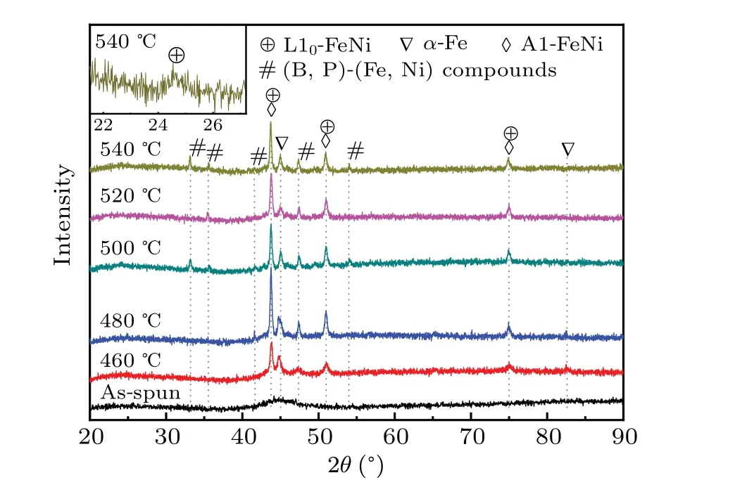
Fig. 1. XRD patterns of Fe42Ni41.3Si8B4P4Cu0.7 ribbons of as-spun state and annealed states at temperatures of 460-540 °C for 1 h with the insert showing(001)superlattice peak of L10-FeNi for the annealed sample at 540 °C for 1 h.

Fig.2. (a)DSC curves with the heating rates of 5 °C/min,10 °C/min,20 °C/min and 40 °C/min. (b) Kissinger plots corresponding to two crystallization stages of Fe42Ni41.3Si8B4P4Cu0.7 amorphous alloy.
After obtaining amorphous ribbons, annealing temperatures have to be determined referring to the DSC measurements. Figure 2(a) shows the DSC curves with the heating rates of 5°C/min,10°C/min,20°C/min and 40°C/min. Two steps of crystallization could be distinguished as two exothermic peaks were observed in each curve. The onset crystallization temperature at each stage(Tx1,Tx2)can be found increasing under higher heating rates asTx1varies from 379°C to 401°C andTx2varies from 465°C to 498°C,respectively.
Activation energies of crystallization can be calculated by linear fitting[Fig.2(b)]based on the Kissinger function[20]

whereβis the heating rate,Txis the onset crystallization temperature at each stage,Exis the activation energy of crystallization andRis the gas constant. As a result, the activation energies (Ex1,Ex2) of the two stages were 322 kJ/mol and 286 kJ/mol,respectively.
3.2. High temperature annealing
Annealing of the amorphous ribbons at 460-540°C for 1 h was performed to investigate the crystallization products with the completion of both crystallization stages. XRD patterns shown in Fig.1 indicate the information of the main crystallized phases during the annealing,includingα-Fe,A1/L10-FeNi and other compounds such as borides and phosphides.However, the fundamental diffraction peaks in L10-FeNi,which are overlapping with those in A1-FeNi,cannot be used to distinguish the A1 and L10phases through XRD patterns,and the L10-FeNi superlattice peaks such as the (001) and(110)ones,theoretically being extremely smaller than the fundamental ones,could only be distinguished in traces of the enlarged pattern as shown in the insert of Fig. 1. Nevertheless,being one of the most concerned property for hard magnetic materials, the coercivity versus temperature with 1 h annealing is plotted in Fig. 3. It is well-expected to find out from Fig.3 that beyond 480°C,higher temperatures lead to smaller coercivity, since it is reported that high temperatures could turn L10-FeNi into soft magnetic and chemically disordered A1-FeNi phase. It is also revealed that although being exposed above the order-disorder transition temperature[12]for 1 h, L10-FeNi phase is not fully removed as the coercivity is still higher than 500 Oe, indicating the phase transition in the FeNi-based alloy system is still very low so that L10-FeNi phase is not fully removed. In comparison, the amorphous ribbons were annealed at 600°C for 1 h, and the coercivity decreased to be less than 160 Oe. On the other hand, the temperature of 460°C seems too low for the amorphous alloy to be fully crystallized within 1 h, since the trace of residual amorphous halo peak can still be observable in XRD pattern(Fig.1).
Therefore,the temperature range of 480-540°C appears to be too high for effective synthesis of L10-FeNi from the amorphous alloy.Since the crystallization of amorphous phase could be completed within a few minutes under such temperatures,prolonged annealing time may only lead to the loss of L10phase,and higher temperatures will make the loss faster.
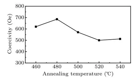
Fig.3. Annealing temperature dependence of coercivity of Fe42Ni41.3Si8B4P4Cu0.7 ribbons annealed at temperatures of 460-540 °C for 1 h.
3.3. Low temperature annealing
A temperature between the two crystallization stages,400°C,was chosen as the annealing temperature to further investigate the formation mechanism of L10-FeNi and improve the coercivity of materials. The structures of annealed ribbons for 10 min,1 h,24 h,138 h and 282 h,were characterized by XRD(Fig.4).Within 1 h annealing,only the diffraction peaks corresponding toα-Fe appear. L10,A1 and some other compound phases emerge and increase rapidly with prolonged annealing time. Despite of the difficulty in detecting superlattice peaks, the (001) superlattice peak was observed in annealed sample for 138 h,as shown in the insert of Fig.4,providing a convincing evidence of L10-FeNi formation.
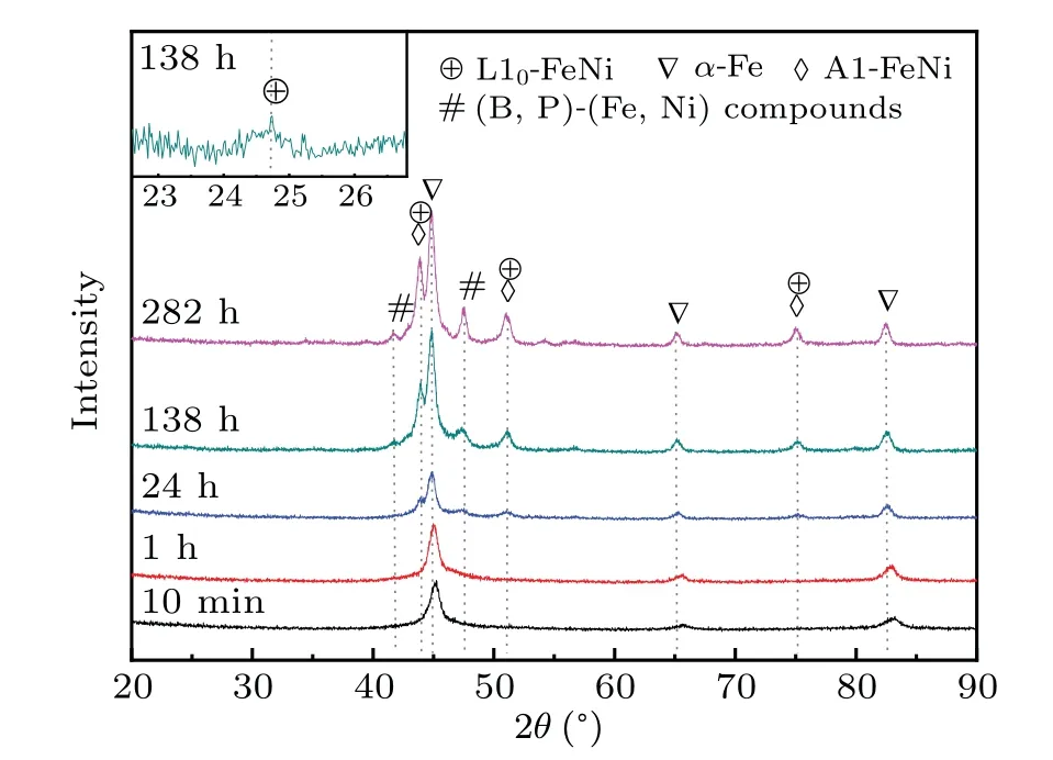
Fig. 4. XRD patterns of Fe42Ni41.3Si8B4P4Cu0.7 ribbons annealed at 400 °C for 10 min, 1 h, 24 h, 138 h and 282 h. The insert shows the(001)superlattice peak of L10-FeNi for the annealed sample at 400 °C for 138 h.
Figure 5(a)presents the hysteresis loops of as-spun state and annealed states(400°C for 10 min,1 h,24 h,138 h,282 h)with the insert of a magnified section at low field.The coercivity evolution of samples is extracted from the hysteresis loops and shown in Fig.5(b). Dramatic rise of coercivity can be observed from the figure as the annealing time reaches 24 h,and the largest coercivity of 861 Oe is obtained in the annealed sample for 138 h. In order to further confirm the existence of L10phase, TEM observation has been adopted. Bright-field TEM image,high-resolution image in TEM image marked by red circle, and diffraction pattern with fast Fourier transformation(FFT)corresponding to the square area(white line)of high-resolution image were shown Fig.6. Mean grain size of crystallized phases is distinguished to be around 27 nm. Diagram of theoretical (111) fundamental and (110) superlattice diffraction of L10-FeNi phase with an intersection angle of 35.3°was depicted in Fig.6(d)as a counterpart for comparison with experimental results. As shown in Fig.6(c),diffraction pattern was very similar to the theoretical diffraction pattern of L10-FeNi[Fig.6(d)]. The results provide a strong evidence for the formation of L10-FeNi in the annealed samples.
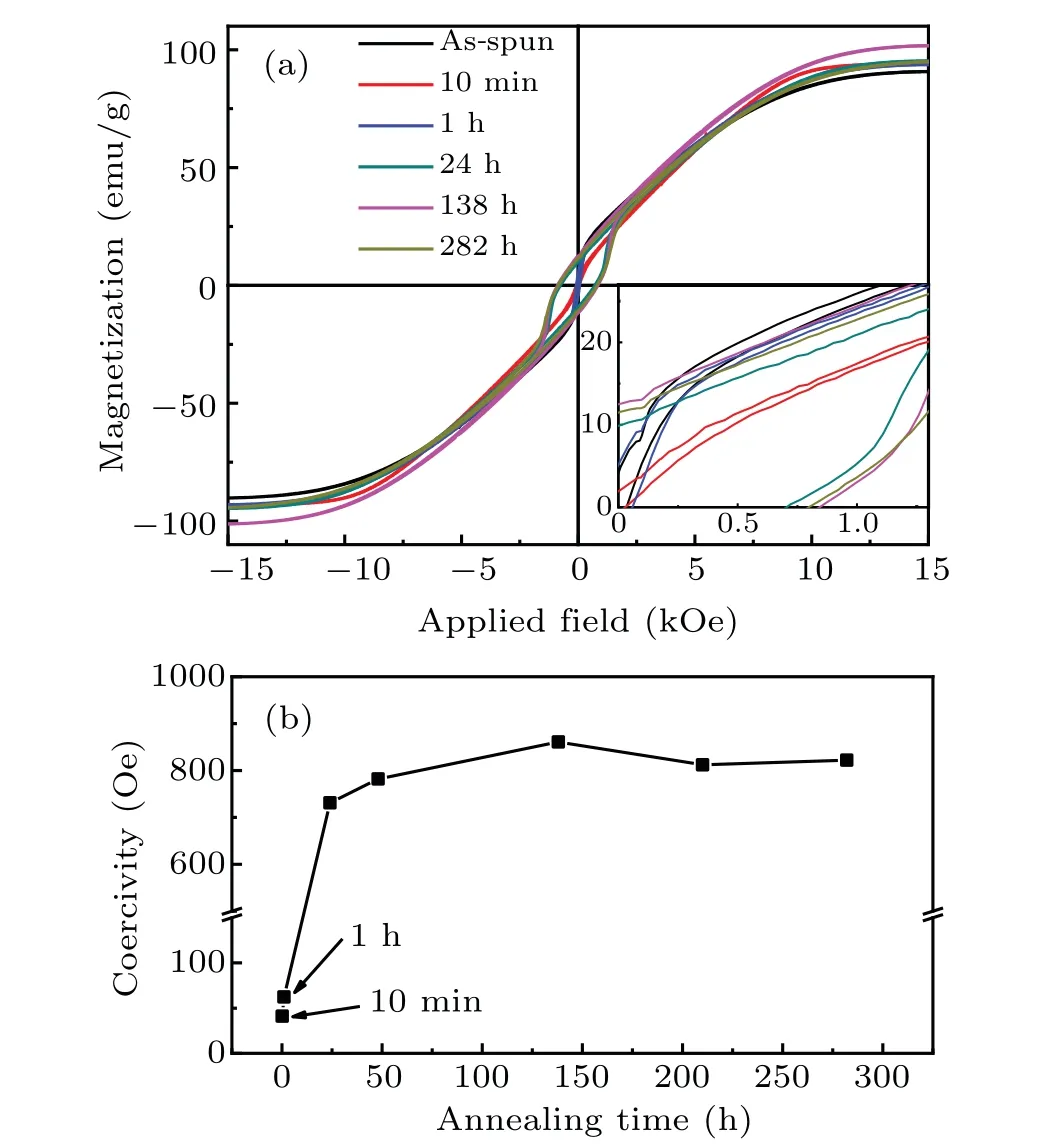
Fig.5. (a)Hysteresis loops of Fe42Ni41.3Si8B4P4Cu0.7 as-spun ribbons and those at 400 °C for 10 min, 24 h, 138 h and 282 h with the insert of a magnified section at low field. (b) Annealing time dependence of coercivity of annealed ribbons at 400 °C.
Both XRD patterns and magnetic measurements indicate that the formation of Fe-Ni phases and other compounds,corresponding to the second stage of crystallization, takes place when the samples are annealed at 400°C for 24 h. Such annealing temperature is lower than the respective onset temperature by more than 60°C,whereTx2is determined by DSC to be around 465°C with a heating rate of 5°C/min. Low stability of the residual amorphous phase is responsible for such behaviors. In fact, after the crystallization of the first stage,the residual amorphous may become more unstable since the activation energy of the second crystallization stage appears to be significantly lower than that of the first one[Fig.2(b)].
Nevertheless,the structure of ribbons continued to evolve for days under 400°C as the coercivity reaches its peak value of 861 Oe when samples have been annealed for 138 h.Such a slow process indicates that the diffusion activity of Fe and Ni in the amorphous alloy under this temperature is still sluggish.

Fig. 6. (a) Bright-field TEM image of annealed sample at 400 °C for 138 h. (b) High-resolution image corresponding to the region marked with red circle in(a). (c)Diffraction pattern after FFT of area marked with white line in(b).(d)Diagram of theoretical(110)fundamental and(111)superlattice diffraction of L10-FeNi phase.
3.4. Stability of L10-FeNi in the annealed ribbons
It was reported that L10-FeNi with highly ordered chemical arrangement could transform into chemically disordered A1-FeNi phase when the temperature goes beyond~320°C.[12]However, L10-FeNi refused to disappear when the alloy ribbons were annealed at 400°C for days in this study,indicating the stability of L10-FeNi formed in the alloy ribbons was somehow enhanced,as shown in Fig.5(b).
Since the transformation from L10-FeNi to A1-FeNi does not involve the participation of other phases or long-range redistribution of the elements,the stability of L10-FeNi against A1-FeNi should not be affected by the other phases. The variation of transformation temperature could only be attributed by the inclusion of other elements in L10-FeNi, and Si is the most possible element in the Fe-Ni-Si-B-P-Cu alloy that can be dissolved in L10phase.
In principle, the thermal stability of phases could be described by the free energy

whereG,H,TandSrepresent Gibbs free energy, enthalpy,temperature and entropy of the phases,respectively. LargerScould help bring downGwhenTrises, thus the chemically disordered A1 phase with larger entropy could become more stable than L10phase at high temperatures. However, the inclusion of other elements may help increase the entropy of L10phase so that it could withstand higher temperature against the A1 phase. With enhanced thermal stability, L10phase could be synthesized more efficiently at higher temperature,and the corresponding atoms should tend to form L10phase instead of A1 phase.
In order to confirm the solubility of Si and some other elements in L10-FeNi and investigate the consequent effects,ab initiomolecular dynamics simulation was carried out. The sampling region includes 2×2×2 unicells of L10-FeNi and one of the atoms (either Fe or Ni) was replaced by Si or Co to find out whether the addition of these elements could be introduced into L10-FeNi phase without seriously deteriorating the magneto-crystalline anisotropy. The systems with or without replacing atoms were firstly relaxed to remove artificial effects and bring lattice deformation that caused by the doping atoms. The system energy change after Si or Co atoms substitution for Fe/Ni was calculated to determine whether the doping atoms could be embedded in the L10-FeNi lattice. The magneto-crystalline anisotropies of systems were calculated to examine if the addition of these elements,which was aimed to enhance the thermal stability of the hard magnetic L10-FeNi phase, will inevitably seriously deteriorate the hard magnetic appearance of L10-phase.
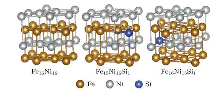
Fig.7.Simulated structures of Fe16Ni16,Fe15Ni16Si1,and Fe16Ni15Si1.
The simulated structures of Fe16Ni16, Fe15Ni16Si1and Fe16Ni15Si1are shown in Fig. 7, and the changes of free energy and magneto-crystalline anisotropy energy(Ku)at 300 K in Fe16Ni16X1, and Fe16Ni16X1(X=Si, Co) compared with those in Fe16Ni16are listed in Table 2. TheKuin L10-FeNi was calculated to be 8.02 J/mol(1.16 J/cm3),reasonably agreeing with the previously reported value of~1.30 J/cm3.Both Si and Co were found soluble in Ni substitutional sites of L10-FeNi as the free energy reduces. Moreover, the addition of Si could reduceKuto 3.98 J/mol,but the addition of Co is found much less harmful to it (7.06 J/mol). Therefore, with certain degree of Si addition,L10-FeNi could have its thermal stability increased due to the increased entropy but magnetic hardness significantly decreased, whereas the addition of Co might theoretically be an even better option since it is much less harmful to the hard magnetic properties.

Table 1. The free energy difference and magneto-crystalline anisotropy energy(Ku)of L10-FeNi with Si or Co addition at 300 K.
To further investigate the dynamical stability of Fe16Ni15X1(X= Si, Co) with L10lattice, phonon properties were simulated as shown in Fig. 8 with a counterpart of L10-FeNi phase for comparison. Positive frequency modes of all these phases indicate the dynamical stability of optimized structures of Fe16Ni15X1(X=Si,Co)and atoms have been in their local most stable positions,agreeing well with the results of system energies.

Fig.8. Phonon dispersion curves of(a)Fe16Ni16,(b)Fe16Ni15Si1 and Fe16Ni15Co1 with L10 lattice.
3.5. Origin of the L10-FeNi in the alloy ribbons
Further improvement of the process requires the clarification of the timing and origin of L10-FeNi formation in annealed ribbons. It is clear that L10-FeNi is not a direct product from the first stage of crystallization as samples annealed at 400°C within 1 h failed to exhibit a high coercivity and FeNi phase could hardly be observed in Fig.4,thus it could only be originated from the residual amorphous phase during second stage of crystallization and/or from pre-formed phases.
In order to clarify these possibilities, experiments were designed as the as-spun ribbons were firstly annealed at 520°C for 3 h or 24 h to be fully crystallized,then kept at 400°C for a period of time to find out whether the crystalline phases could contribute to the formation of L10-FeNi under such annealing temperature. Coercivity values of annealed samples were shown in Table 2. When it is annealed under 400°C,the rise of coercivity takes place mainly during the period from 1 h to 24 h, accomplished with the disappearance of residual amorphous signal in the XRD patterns,indicating that the L10phase is mainly precipitated from the residual amorphous during the second crystallization stage. However,slight increment of coercivity could also be observed during annealing under 400°C after full crystallization as have already been annealed under 520°C for 3 h or 24 h. Such increment is probably due to the limited transformation from other high temperature crystalline phases towards L10phase, or the removal of B from L10lattice and improvement of the ordering quality of the L10phase due to the reduced temperature from 520°C to 400°C.

Table 2.Coercivity evolution of annealed ribbons under various conditions.
3.6. Direction dependent hysteresis behavior of the sheet samples
It is reasonable to believe that the microstructures of annealed samples are isotropic since they were made from amorphous structure without external stress or other anisotropic effects. However, hysteresis loops of annealed samples as well as the coercivity appear to be different at various directions,as shown in Fig. 9, thus the anisotropic shape of sample should be the main reason.
The annealed samples consist of hard magnetic L10-FeNi phase, soft magneticα-Fe and A1-FeNi phases, and some other compound phases. During a magnetic reversal process,some of soft magnetic regions will yield to the external magnetic field easily,and the increasing magnetic field will expand the reversed regions as the domain wall propagates. The hard magnetic L10-FeNi grains,which have their magnetic moment hard to change,will act as pinning sites that prevent the propagation of the domain walls,leading to the rise of coercivity.
In samples with a shape of sheet,the domain wall should always be perpendicular to the sheet plane to minimize the area as well as the energy of it, thus only the in-plane part of the magnetic field is effective to the propagation of domain wall. Overcoming the pinning sites requires the effective magnetic field to reach a certain threshold. When the angle between the field and sample plane (θ) increases,larger coercivity is measured following a simplified Kondorsky model, and such a phenomenon is well-discussed in previous reports.[21,22]

Fig. 9. (a) Hysteresis loops of Fe42Ni41.3Si8B4P4Cu0.7 annealed ribbons at 400 °C for 138 h with applied magnetic field in the angle of 0 °,82 ° and 90 ° with respect to the sample plane. (b) Direction dependence of coercivity of ribbons annealed at 400 °C for 24 h,138 h 210 h and 282 h.
The monotonic increase of coercivity withθbecomes reversed whenθgoes close to 90°. At high angles, instead of easy reversal, the moments of soft magnetic regions are confined to reduce the net out-of-plane moment due to the strong demagnetization effect. In order to cancel the magnetic moment of hard magnetic phases,the soft magnetic phase will exhibit opposite magnetic moment to form magnetic dipoles,and the changing of external magnetic field could only take effect on forming or breaking these dipoles. Thus,no sharp change of magnetic moment could be observed from the hysteresis loops at 90°,and the coercivity becomes greatly reduced since the demagnetization field already takes strong effect on reducing the magnetic moment towards zero in the measured direction.
Therefore, the difference of magnetic behaviors in various directions of the sample is determined by both domain wall pinning effect and demagnetization effect, the former of which is dominant at low angles with respect to the sample plane and the latter become dominant at high angles.
3.7. Discussion on the improvement of the process
Up to now, achieving 861 Oe by annealing FeNi-based amorphous ribbons is still far from the purpose of fabricating application-worthy L10-FeNi hard magnets.To further improve L10-FeNi magnets by annealing amorphous alloys, we should mainly focus on the following factors.
Firstly,the addition of some elements,such as Si or Co,is considered promising to improve the thermal stability of L10-FeNi. With enhanced thermal stability, amorphous structure will tend to crystallize into more L10-FeNi instead of A1-FeNi,and the process could be operated at higher temperature for faster synthesis.
Secondly, amorphous alloy composition with lowTxof the critical stage should be found. Since L10-FeNi always has higher chemical ordering and smaller entropy than A1-FeNi,lower temperature will make the free energy difference between L10-FeNi and A1-FeNi become larger,thus the amorphous alloy will prefer to crystallize into L10-FeNi more rather than A1-FeNi.
Besides, it is found that the first stage of crystallization has hardly any direct contribution to the formation of L10-FeNi. Therefore, the alloy composition could be redesigned to remove part of Fe and to remove Cu that is practical in promotingα-Fe formation but not effective for the formation of L10-FeNi. The volume fraction of L10phase probably is increased and the coercivity would be improved when the precipitation ofα-Fe is suppressed.
4. Conclusion
The formation mechanism of L10-FeNi through annealing Fe42Ni41.3Si8B4P4Cu0.7amorphous alloy has been studied. The maximum coercivity of 861 Oe was obtained in the sample prepared by annealing amorphous ribbons at 400°C for 138 h. Annealing at higher temperature will result in smaller coercivity since L10-FeNi could transform into A1-FeNi, but too low temperature could greatly slow down the preparation progress. L10-FeNi in the annealed ribbons was mainly precipitated from the residual amorphous alloy during the second crystallization stage.A slight increase of coercivity was found for fully crystallized samples annealed at 400°C,probably due to limited transformation from other high temperature crystalline phases towards L10phase,or the removal of B from L10lattice and improvement of the ordering quality of the L10phase due to the reduced temperature from 520°C to 400°C.
It is found that the L10-FeNi formed during annealing at 400°C is stable. According the computational simulation,the substitution of Si or Co for Ni sites in L10-FeNi lattice could enhance the stability of L10phase.
It is revealed that the difference of magnetic behaviors in various directions of the sheet samples is caused by the domain wall pinning effect and demagnetization effect, leading to the phenomenon of non-monotonic direction dependent coercivity with peak values lies in the angle of 82°to sample plane.
Acknowledgements
This work was supported by the National Natural Science Foundation of China (Grant Nos. 51971179 and 51971180),the Natural Science Foundation of Chongqing, China (Grant No. cstc2019jcyj-msxmX0328), Shaanxi Provincial Natural Science Foundation, China (Grant No. 2020JM-112),Guangdong Provincial Science and Technology Program,China (Grant No. 2019B090905009), the Fundamental Research Funds for the Central Universities of China (Grant No. D5000210731), and Shaanxi Provincial Key R&D Program, China (Grant No. 2021KWZ-13). The computational work was performed on supercomputing system in Institute for Materials Research,Tohoku University.
猜你喜欢
杂志排行
Chinese Physics B的其它文章
- Helium bubble formation and evolution in NiMo-Y2O3 alloy under He ion irradiation
- Dynamics and intermittent stochastic stabilization of a rumor spreading model with guidance mechanism in heterogeneous network
- Spectroscopy and scattering matrices with nitrogen atom:Rydberg states and optical oscillator strengths
- Low-overhead fault-tolerant error correction scheme based on quantum stabilizer codes
- Transmembrane transport of multicomponent liposome-nanoparticles into giant vesicles
- Molecular dynamics simulations of A-DNA in bivalent metal ions salt solution
