Function Analysis and Simulation Research on Powertrain for Fuel Cell Electric Vehicles
2022-04-08WuQinglongYuChanghongWangYanLiuLiyuan
Wu Qinglong · Yu Changhong · Wang Yan · Liu Liyuan
(1. New Energy Vehicle Development Institute, China FAW Corporation Limited, Changchun 130013; 2. State Key Laboratory of Comprehensive Technology on Automobile Vibration and Noise & Safety Control, Changchun 130013)
【Abstract】This paper introduces the powertrain structures of fuel cell electric vehicles. The system functions, drive modes and control strategies of the fuel cell electric vehicle are analyzed. Based on CRUISE simulation software, the whole vehicle and powertrain models of a fuel cell electric vehicle are built. The performance simulation and analysis on the fuel cell electric vehicle are carried out under NEDC driving cycles. The results show that the simulation software can predict the vehicle performance index in advance. At the same time, the developments of fuel cell electric vehicle are prospected at the end of this paper, and relevant suggestions are put forward to provide references for engineering designers.
Key words: Fuel Cell Electric Vehicle (FCEV), Powertrain, System structure, Function analysis,Modeling and simulation

BMS Battery Management System CAN Controller Area Network DC/DC Direct Current to Direct Current converter FCEV Fuel Cell Electric Vehicle FCCU Fuel Cell Control Unit FCS Fuel Cell System HCU Hybrid Control Unit HMI Human Machine Interface
HV High Voltage IC Instrument Cluster MCU Motor Control Unit NEDC New European Driving Cycle SOC State Of Charge UDC Urban Driving Cycle EUDC Extra Urban Driving Cycle
1 Introduction
At present,in order to deal with the energy crisis and environmental issues,the fuel consumption laws and regulations of various countries are becoming much stricter.The advantages of new energy vehicles in energy conservation and environmental protection have attracted more and more attentions. FCEV has the advantages of zero emission, long driving range, fast fuel filling and low noise. The research and development on FCEV have gradually become one of research hot spots in automotive industry around the world. Hydrogen fuel can be produced through a variety of disposable energy sources,and is expected to become one of the conventional fuels in the future.
The technologies of FCEV across the globe have developed rapidly, and significant technology breakthroughs have been observed in fuel cell materials and stacks. Relevant accessory suppliers are also actively entering into the field of fuel cell technology research and product development. Meanwhile the development processes of FCEV industry have been promoted.Nowadays,many countries have promoted fuel cell electric vehicles to the development stage of industrialization. Automobile manufacturers represented by Toyota, Honda and Hyundai have vigorously promoted fuel cell electric vehicles.Fuel cell vehicle types,such as Hyundai ix35FCV,Toyota Miraiand Honda Clarity, have been mass-produced and pumped into markets since 2014, while premium car manufacturers, such as Mercedes Benz, BMW and Audi,have been promoted the research of fuel cell technology.
Based on a fuel cell electric vehicle, this paper introduces the configuration schemes of powertrain,and analyzes the system functions, driving modes and control strategies. Based on CRUISE simulation software, the whole vehicle and powertrain models are built based on the fuel cell electric vehicle(sample vehicle),and the vehicle performance simulation calculation and analysis are carried out to provide references for relevant designers.
2 Structural Scheme of Powertrain
The powertrain system structural scheme of the fuel cell vehicle is shown in Fig. 1. It mainly includes: hydrogen cylinder,fuel cells,fuel cell control unit(FCCU),HV battery,BMS,HCU,MCU,Inverter,traction motor and transmission components. The fuel cells system(FCS) is connected with the inverter through the booster DC/DC to realize the decoupling control of HV battery and fuel cells.The power battery is directly connected with the inverter through the DC/DC output terminal.

Fig.1 The structure of FCEV powertrain
Fuel cell electric vehicle has the advantages of dynamic performance and economy performance, and can realize the unique system functions. The system functions of powertrain mainly include fuel cell independent drive, HV battery independent drive, and combined drive, driving power generation, parking power generation, energy recovery, flat road crawling and slope road crawling.The system functions of various modes are elaborated and summarized in the following chapters.
3 Powertrain System Functions
3.1 Fuel Cell Independent Drive
As shown in Fig. 2, in case of fuel cell independent drive, the fuel cell provides electric energy to the motor to drive the vehicle. HCU calculates the driver’s required torque according to vehicle speed,accelerator and brake pedal position, transmission gear, and the power of fuel cell. HCU sends the required torque to the motor and drives the vehicle.

Fig.2 Energy flow of fuel cell independent drive
3.2 HV Battery Independent Drive
As shown in Fig. 3, in case of HV battery independent drive, the HV battery provides electric energy to the motor to drive the vehicle when the SOC value is higher than the setting value. HCU calculates the driver’s required torque according to vehicle speed,accelerator and brake pedal position, transmission and the power of HV battery. HCU sends the required torque to the motor and drives the vehicle.

Fig.3 Energy flow of power cell independent drive
3.3 Combined Drive
As shown in Fig. 4, in case of combined drive, the fuel cell and HV battery cell jointly provide electric energy to the motor to drive the vehicle.HCU calculates the driver’s required torque according to vehicle speed, accelerator and brake pedal position,transmission gear,and the power of fuel cell and HV battery. HCU sends the required torque of combined drive to the motor and controls the motor to drive the vehicle. The required torque is different under different gears and driving modes, and the torque output at the motor end is different.

Fig.4 Energy flow of combined drive
The combined drive of fuel cell and HV battery can ensure the dynamic performance of the vehicle and the service life of the battery. When the required power driven by the vehicle is greater than the maximum power of the fuel cell, the fuel cell operates at the maximum power,and the rest is supplemented by the HV battery to ensure dynamic performance of the vehicle. When the fuel cell works in a stable range,the power demand of the vehicle under variable load can be supplemented by the HV battery to ensure the service life of the fuel cell.
3.4 Driving Power Generation
If the SOC of the HV battery is lower than a certain threshold value during the vehicle driving, the fuel cell can be switched to increase the power output to charge the HV battery. The entry condition of the driving power generation mode is when the SOC of HV battery is lower than 30%, the fuel cell can be adopted to charge the HV battery. The exit condition is when the SOC of HV battery is higher than 70%.
As shown in Fig. 5, when the SOC of HV battery is at the medium level, if the driving power demand at this time is less than the minimum power that the fuel cell can output, the fuel cell can be controlled to work at the minimum power point, and the excess power output is used to charge the HV battery.When the SOC of HV battery is at low level, the fuel cell can supply power to the motor and charge the HV battery at the same time, so as to maintain the balance of the SOC of HV battery.

Fig.5 Energy flow of driving power generation
3.5 Parking Power Generation
When the vehicle pulls over, if the SOC of HV battery is lower than a certain threshold value, the fuel cell can be used to generate electricity to charge the HV battery. As shown in Fig.6,the entry condition of parking power generation mode is that the SOC of HV battery is lower than 30%,and the fuel cell can charge the HV battery.The exit condition is that the SOC of HV battery is higher than 40%.

Fig.6 Energy flow of parking power generation
3.6 Energy Recovery
When the vehicle shift lever is in D or R gear, the vehicle speed exceeds a certain threshold value (e.g. 10 km/h) and the SOC of HV battery is lower than a certain threshold value, the ABS and ESP system have no fault.At this time, if the driver releases the accelerator pedal and brake pedal, the vehicle will enter the sliding state,and the motor will enter the power generation mode to convert the dynamic energy into electric energy and store it in HV battery. HCU calculates the required negative torque of the motor according to the vehicle sliding state and sends the negative torque value to MCU. MCU controls the motor to generate power and charge the battery,the energy flow of recovery is shown in Fig.7.
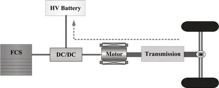
Fig.7 Energy flow of recovery
When one of the following conditions occurs,the energy recovery function shall be exited.
(1)The driver places the shift lever in N or P gear;
(2)The driver depresses the accelerator pedal;
(3) Energy recovery is not allowed for motor or battery in some conditions;
(4) The vehicle speed is less than a certain threshold value(e.g.10 km/h);
(5)There are some faults in ABS or ESP system.
3.7 Flat Road Crawling
In case of the flat road crawling,when the shift lever is in D or R gear, and the accelerator pedal and brake pedal are not pressed by the driver, if the vehicle starts crawling from stationary,the speed shall be controlled to maintain at a stable speed of 4 ~6 km/h on the flat road.When the driver shifts the vehicle, depresses the brake pedal or depresses the accelerator pedal, the flat crawl mode will be exited.
3.8 Slope Road Crawling
In case of slope road crawling, when the shift lever is in D or R gear, and the accelerator pedal and brake pedal are not pressed by the driver, if the vehicle starts crawling from stationary,the speed shall be controlled to maintain at a stable speed which is lower than that of the flat road, and the maximum crawling slope during electric crawling shall not exceed a certain value (e.g. 8%). The maximum torque in the crawling process is fixed which can be calibrated,and the crawling speed decreases gradually with the increase of slope. When the driver shifts the vehicle, depresses the brake pedal or depresses the accelerator pedal,the slope crawl mode will be exited.
4 Vehicle Driving Mode Analysis
4.1 Driving Mode schemes
There are 3 driving modes designed for the fuel cell electric vehicles in this paper, including normal mode, sport mode and E-pedal mode.
Normal mode is a default driving mode, this model fully considers the dynamic and economy of the vehicle.In this driving mode, the power of the traction motor and the capacity of the air conditioner are not limited, and the deceleration of vehicle sliding with gear is small.This driving mode meets the needs of most drivers.
Sport mode is mainly adopted to meet the requirements of the vehicle dynamic performance. The accelerator pedal response is much faster than that of normal mode. The vehicle shows good acceleration dynamic performance.
In E-pedal mode, the driver can accelerate and decelerate the vehicle through the accelerator pedal. At the same time,the driver can release the accelerator to a certain extent without stepping on the brake pedal.If the vehicle needs to have a large deceleration, the brake pedal needs to be pressed. This mode can be used for special working conditions such as intense driving and mountain driving.
The comparative analysis of the three driving modes is shown in Table 1.
4.2 Driving Mode Display
In order to further increase the HMI,different instrument display schemes can be designed based on the system functions of fuel cell electric vehicle and driving modes,so as to improve the driving experience of users.During the operation of fuel cell electric vehicle, HCU sends the display signals of energy flow and driving mode to IC,and then IC displays the corresponding mode information. The sending signals from HCU to IC are shown in Fig. 8, and the specific network signals are shown in Table 2.

Fig.8 Energy flow and driving mode signals

Table 1 Comparative analysis of the driving modes

Table 2 CAN-bus network signals
When IC receives the energy flow signal sent by HCU, it displays the different graphic. For example, in case of the combined drive, IC shall be able to display the energy flow status of engine operation, motor output torque and battery discharge. When IC receives the driving mode signal sent by HCU, it displays a driving mode according to the value of the signal. Different graphics are helpful for the driver to understand the current operation state of the powertrain system.
5 Modeling and Simulation
In CRUISE simulation software, the models of various components of the fuel cell electric vehicle are established.Based on the above functional analysis,the different models of control strategies are built,including driving control modes, combined drive, separate drive and other strategy modules. The CRUISE simulation software is used to calculate the dynamic and economy of the vehicle.The established simulation model of the fuel cell electric vehicle is shown in Fig.9.The relevant parameters of the fuel cell electric vehicle are shown in Table 3,and the parameters of each component are shown in Table 4.

Table 3 Relevant parameters of FCEV
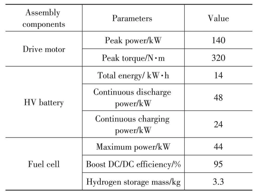
Table 4 Parameters of main components

Table 5 Simulation results of vehicle performance

Fig.9 Simulation model of fuel cell vehicle
According to the parameters of the fuel cell electric vehicle and various components of the powertrain system,the models are built in the CRUISE simulation software.The economy performance simulation calculation of the vehicle is carried out under NEDC cycle conditions. The NEDC working condition spectrum is shown in Fig. 10.For the data statistics of specific working conditions,please refertothenationalStandardsGB/T 18386—2017.

Fig.10 NEDC cycle spectrum
The NEDC cycle consists of 4 Urban Driving cycles(UDC) and 1 Extra Urban Driving Cycle(EUDC). The driving distance is 11.022 km and the time is 1 180 s.The UDC cycle is conducted to simulate urban road conditions. Each UDC includes acceleration, deceleration,uniform speed and idle speed.The duration of the 4 UDC conditions is 780 s and the theoretical driving distance is 4.067 km. EUDC cycle is carried to simulate suburban road conditions, with a duration of 400 s, a theoretical driving distance of 6.956 km and a maximum speed of 120 km/h.
Fig. 11 to 13 show the motor output speed, torque and power under the NEDC driving cycle. The established software model can realize normal driving according to the control strategies, including fuel cell independent drive, HV battery independent drive, combined drive and driving power generation.The simulation calculation is based on CRUISE software, and the simulation results of vehicle performance are shown in Table 5. The established simulation model can be applied to simulate the dynamic performance and economy performance of fuel cell electric vehicle, and has the effects of prediction in the early stage of vehicle development.

Fig.11 Speed output of traction motor
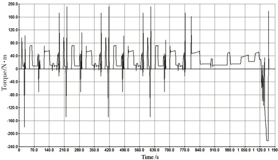
Fig.12 Torque output of traction motor
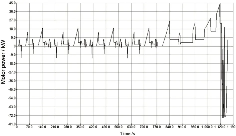
Fig.13 Power output of traction motor
6 Conclusion
This paper analyzes the system function, drive modes and control strategies of fuel cell electric vehicle. Based on CRUISE software, the performance of a fuel cell electric vehicle is simulated and analyzed. In the stage of vehicle design and development, the simulation software is applied for calculation and research, which can be used to provide references for engineering designers.
At present, the development of hydrogen fuel cell electric vehicles has obvious advantages, and the relevant technologies of hydrogen fuel cell vehicles have made substantial breakthroughs,and the policy is also increasing guidance. However, there are still some constraints.For large-scale development in the future,in addition to improving the core technologies, the improvement of infrastructure is necessary and imperative to speed up, such as the establishment of multiple hydrogenation stations which can be used to improve the convenience of hydrogen filling for customers. In addition, the vigorous development of fuel cell electric vehicles also requires the joint efforts of the governments and enterprises, continuously strengthen the demonstration operation,and appropriately explore new business operation modes.
