X-ray focusing using an x-ray lens composed of multi-square polycapillary slices
2022-02-24KaiPan潘凯TianChengYi易天成ZhaoWang王瞾MoZhou周末YuDeLi李玉德ZhiGuoLiu刘志国XiaoYanLin林晓燕andTianXiSun孙天希
Kai Pan(潘凯), Tian-Cheng Yi(易天成), Zhao Wang(王瞾), Mo Zhou(周末), Yu-De Li(李玉德),†,Zhi-Guo Liu(刘志国), Xiao-Yan Lin(林晓燕)1,, and Tian-Xi Sun(孙天希)
1College of Nuclear Science and Technology,Beijing Normal University,Beijing 100875,China
2Beijing Key Laboratory of Applied Optics,Beijing 100875,China
3Key Laboratory of Beam Technology,Ministry of Education,Beijing 100875,China
4Spallation Neutron Source Science Center,Dongguan 523803,China
5Institute of Applied Electronics,China Academy of Engineering Physics,Mianyang 621900,China
A new type of x-ray lens composed of multi-square polycapillary slices (ASPXRL) used in focusing parallel x-ray beam was presented in this paper.Compared with conventional x-ray polycapillary lens,ASPXRL can provide smaller and brighter focus.The effects of the manufacturing imperfections on focusing quality of ASPXRL were evaluated with the values of transmission efficiency and discussed.It is suggested that ASPXRL has application prospects as a condenser lens for x-ray microscopy and flux collectors for x-ray analytical instruments.
Keywords: x-ray optics,polycapillary x-ray lens with square channels
1.Introduction
The x-ray optics has grown rapidly in recent years to satisfy numerous actual applications.As an important branch of x-ray optics, different kinds of optical elements have been developed to transport radiation from source to sample.These optical elements include K–B mirror optics,[1]lobster-eye lens,[2]x-ray multilayer mirrors,[3]polycapillary lens,[4]and so on.They can provide more powerful, highly concentrated or approximately monochromatic beams through different controlling mechanisms.As one kind of widely used optical elements for all types of x-ray analysis, x-ray polycapillary lenses illustrated their utility in x-ray lithography,[5]x-ray astronomy,[6]x-ray diffraction analysis,[7]x-ray fluorescence,[8]medicine,[9]and other scientific fields.
Polycapillary x-ray lenses have been used cooperatively with conventional x-ray sources successfully.These lenses are fabricated with bundles of hollow glass capillary tubes.They focus, collimate and filter x-ray radiation based on the principle of total external reflection (TR).Collimating polycapillary optics (CPO) can convert a highly divergent beam into a quasi-parallel beam with small divergence angle.When used in large area diffraction,quasi-parallel beam increases the diffraction intensity of a crystal.[10]In addition,CPO provides nearly complete scatter rejection when implemented in x-ray medicine imaging.It can be used to magnify or demagnify the x-ray imaging with improved contrast and resolution.[11]For conventional CPO,arrangement of circular channels leaves the problems of triangular-shaped nonfunctional spaces between the capillaries.This structural flaw leads the lower flux gain when it is used in x-ray diffraction analysis.Moreover,especially in x-ray medical imaging,lacks of the feature points of the images will make important diagnostic information missing.To overcome these shortcomings, a new type of x-ray lens composed of multi-square polycapillary slices was proposed.In our previous papers, we studied the transmission of x-ray in an ideal 84-mm long CPO and discussed its potential applications for spatial image.[12]However, as further investigations,[13]it is hard to manufacture such a long monolithic polycapillary with square channel due to the limitation of technological level at present.Therefore,we assembled an xray lens with multi-square polycapillary slices.The structural support was obtained through three-dimensional(3D)printing technique and the printing material was polylactic acid(PLA).
In this paper, we presented an x-ray lens composed of multi-square polycapillary slices (ASPXRL).ASPXRL was arranged with a stack form in a 3D printing skeleton.We corrected previous numerical model to comply with the actual situation of this lens.In experimental part,ASPXRL was used for x-ray focusing.The primary parallel beam was obtained by a polycapillary parallel x-ray lens with circular channels.Compared with conventional polycapillary x-ray lens,ASPXRL produced much higher quality focusing.In addition,errors including displacement and axis deviation were considered to explain the imperfections of the focus.
2.Materials and methods
2.1.Geometric structure
As introduced in previous work,[13]manufacturing of square polycapillary slices has four main procedures: drawing,arraying,slicing,and corroding.Because the square channels are bended,smooth internal surface cannot be guaranteed while corroding the square core rod.Hence, considering machining efficiency as well, the thickness of final product of these slices are controlled between 0.5 mm to 3.0 mm.To realize a long length x-ray polycapillary lens,we selected a simple assembled manner.As shown in Fig.1, the geometric structure is constituted of two parts: structural support and square polycapillary slices.The holding structure was machined using 3D printing technique and the material is PLA.0.5-mm width and 1.0-mm depth slots were cut along the transverse direction in the inner bottom surface of the groove.Different sizes of polycapillary slices were imbedded in the center of the 3D printing blocks.Then, these blocks were inserted into the slots.The centers of the slices should be kept in a unitive optic axis in standard.Through this stack-like arrangement,shape of the external walls of ASPXRL can be perceived as a quadratic curve.Each slice contributed a discrete arc in the curve, as illustrated in Fig.2(a).Figure 2(b) shows the scanning curve of the square cone multi-fiber bar before being sliced.Because of tiny mechanical vibration and temperature control in the process of drawing rods, here exists a fluctuation.We selected a segment of the fitted quadratic curve based on the scanning data.The parts with big relative fluctuation in either two scanning directions (vertical and horizontal) were dropped when manufacturing the slices.In fact,limited by the precision of 3D printing technology,ASPXRL was assembled after some practice to make sure each slice placed in the right position.

Fig.1.(a)Idealized structure of ASPXRL.(b)Actual device for experiment.(c) Individual square slice No.43 imbedded in the center of ASPXRL.(d)Microphotography of the square polycapillary slices.

Fig.2.(a)Schematic diagram of the arrangement of ASPXRL.(b)Scanning curve of the square cone multi-fiber bar before being sliced, S1–S5 correspond to the five slices used in assembly, and other parts of the rod will be dropped due to obvious fluctuations in either two scanning directions(horizontal and vertical).
2.2.Simulation model
Based on our previous works,[12–15]the simulation model is illustrated in Fig.3.Entire assembled lens was positioned in a Cartesian coordinate system.Thezaxis passed through the central channel and served as an optical axis.The center of an extended Gaussian area source was placed with coordinate(0,0,ls).The source function is denoted by

whereN0is the primary number of x-ray photons emitted per second from the source,rsis the radius of the source, andr=corresponds to the emission position of the photons.
Five slices S1–S5 were placed in order of sizes,S1 has the smallest cross section area while S5 has the largest.The intervals between two adjacent slices are determined by the width of the dropped parts,which have been illustrated by Fig.2(b)before.The intervals are denoted bytaij.For example, the interval between S1 and S2 ista12.The incident plane of S5 coincides with planeXOYand served as the lens entrance.Its edge length is 2Din.The output plane of S1 served as the lens exit and its edge length is 2Dout.For the shape curve of ASPXRL is quadratic,it has a simple expression

wherea0andb0can be obtained from the scanning data of Fig.2(b).

Fig.3.Schematic diagram of the simulation model.Rays emitted from an extended source S at a distance ls from the center of slices.Then,guided by ASPXRL and projected to the detector plane at a distance li from the output plane.
Assumed that the assembled lens has(2n+1)×(2n+1)channels.For an individual square channel in row m,column n, its internal width isdinand wall thickness is t in the input plane.Equations of the four internal walls(the upper,the lower,the left and the right)can be expressed as follows:

wheretsiis the thickness of the slices andkdenotes the label number of the slices.
Put this model into the field of geometric optics.Rays leaving the source reflected off the interior walls of the channels of the slices and transmitted through the air intervals alternately.The detector plane was divided into(2n+1)×(2n+1)square blocks with edge length resdµm.And the pixels of the detectors have a one-to-one correspondence with the square channels of ASPXRL.The value of resdwas determined by the resolution of the CMOS camera in practice.By recording counts in each pixel,many optical properties such as output intensity distribution, divergence angle, transmission efficiency and gain can be calculated.
2.3.Experimental arrangement
Figure 4(a) shows the schematic diagram of the experimental setup and figure 4(b) is a photography of the experimental setup.The x-ray beam was generated by an x-ray tube with a Cu target[MCBM 50-0.6B,RTW,Germany].The focal spot was ~50µm in diameter.The ASPXRL was placed between a quasiparallel polycapillary x-ray lens with circle channels (PPXRL1) and a CMOS camera.PPXRL1 was used to obtain parallel x-ray beams.The slices used in assembly was designed and manufactured by the College of Nuclear Science and Technology of Beijing Normal University.Detailed parameter of individual slices and the entire assembled lens are listed in Table 1.At the end of the setup was an x-ray imaging system[C11440-42U30,Hamamatsu,Japan]which was used to detect the output counts of the detected x-ray.The resolution of the x-ray imaging system was 6.5 µm.For comparison,the ASPXRL was then replaced by another conventional polycapillary x-ray lens (PPXRL2).Detailed parameters of PPXRL1 and PPXRL2 are listed in Table 2.

Table 2.Detailed parameters of PPXRL1 and PPXRL2.

Fig.4.(a)Schematic diagram of the experimental arrangements.(b)Photograph of the experimental setup.
3.Results and discussion
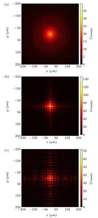
Based on the simulation model, we used a Monte-Carlo raytracing program to do the numerical calculations.Because of the limitation of output area of PPXRL1, ASPXRL was partly illuminated by the quasi-parallel beam.Because open area ratio and irradiated area of PPXRL2 and ASPXRL are the same,the input flux of these lens were the same.Figure 5 shows the simulation results.The focal length was 30.00 mm in all cases.The incident photon numbers used in simulations is 2×10⁷.For conventional polycapillary lens with circular channels, the shape of its focal spot is a circle.A halo exists at the edge of the spot for divergency.Figures 5(b) and 5(c)are the cases of the ideal and real conditions of ASPXRL.In Fig.5(b), ASPXRL was a monolithic lens with no intervals.In Fig.5(c),the lens was assembled with five slices and there existed air intervals.Both in the two cases,the shape of the focal spot was a cross.In the process of multiple total reflection,in real condition,the rays cannot be guided rightly because of the existence of the air intervals.This caused intensity loss in the central part of the focal cross and some dark stripes that had no recorded photons in the cross arm.Meanwhile, misguided rays contributed to the background that are useless for focus.This problem can be overcome by decreasing the length of the intervals which rely on the development of the corrosion technology.

Fig.5.Simulation results of focal spot: (a) conventional polycapillary lens PPXRL2;(b)ASPXRL without air intervals;(c)ASPXRL with air intervals.
Figure 6 shows the experimental results.The voltage and currents of the x-ray tube were set to 30 kV and 400µA.The exposure time of the camera was set to 2 seconds.The focal length of PPXRL2 and ASPXRL were 35.0 mm and 36.0 mm,respectively.In good agreement with the simulation results,using ASPXRL for focusing, the focal spot was a cross with bright center and twodimensional cross arms.Here existed some dark stripes that have no recorded photons for the photon loss in the air intervals.And the background caused by the misguided rays was obvious.The full width of the crosslike focal spot was 600µm,while the full width of the circular focal spot was 400µm.Figure 7(a)is the intensity profile in one dimension(orange line marked in Fig.6)of the focal spot for PPXRL2 and ASPXRL.The profiles showed similar Gaussian distributions.The full width at half maxima(FWHM)of the fitted curves was 156 µm for PPXRL2 and 104 µm for ASPXRL.In the range of FWHM,the integrated intensity for ASPXRL was about 1.5 times as PPXRL2.Compared with conventional polycapillary x-ray lens,using ASPXRL can obtain smaller and brighter focal spot.Due to the existence of the background caused by misguided rays, the full width of ASPXRL is larger than PPXRL2.Figure 7(b)shows the measurement results of divergence of PPXRL2 and ASPXRL.The x-ray camera was moved with a step of 1 mm.As distance between the lens exit and the camera increases, the FWHM of the transverse beam size first decreases and then increases.The value reaches the minimum in the position of focal length.The measured divergence of PPXRL2 was 8.4 mrad and of ASPXRL was 8.0 mrad.The depth of focus was shorter for ASPXRL compared with PPXRL2.In theory,the depth of focus is same for the two lenses because of the same geometric structure in longitude.The difference mainly comes from the fluctuation in the curve shape during manufacturing.

Fig.6.Experimental results of focal spot using ASPXRL and PPXRL2 for focusing.
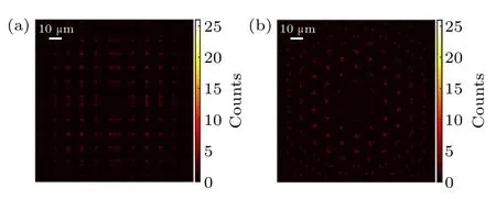
Similar divergence and depth of focus suggested that ASPXRL could be used in the same field as that of the conventional polycapillary x-ray lens.The advance of this new type lens is that it can provide smaller and brighter focal spot as mentioned above.This owes to the “corner cube” effect of square channels.[16]With circular channels,there exists a central line along the cylindrical channel.Rays parallel to the central line will reflected back to the optic axis.If the hit point of TR is away from the central line, the rays will divert away from the optic axis and cause severe focusing errors.Figure 8 is the simulated results of the photon distribution in the exit plane of these two lenses.The photon distribution in ASPXRL is square-like while in PPXRL2 is crescent.With “corner cube” effect, the photons guided by ASPXRL contributes to the cross-like focal spot with a magnitude depends on the channel width.As shown in Fig.8(b),with layer number increasing,more photons hit on the circular channels with a position away from the central line.It leads to significant focusing errors.Thus,it can be explained that using ASPXRL produces higher quality focusing compared with lens with circular channels.

Fig.7.(a)Intensity profiles in one dimension of the focal spot for PPXRL2 and ASPXRL.(b)Divergence of PPXRL2 and ASPXRL.

Fig.8.Simulated results of the photon distribution in the exit plane of (a)ASPXRL and(b)PPXRL2.

Fig.9.(a) Diagram of displacement error.(b) Diagram of axis deviation error(transverse and longitudinal).

Fig.10.Focal spot effected by manufacturing imperfections: (a) 5.00-µm random displacement error; (b) 0.1-rad transverse axis deviation error; (c)0.01-rad longitudinal axis deviation error.

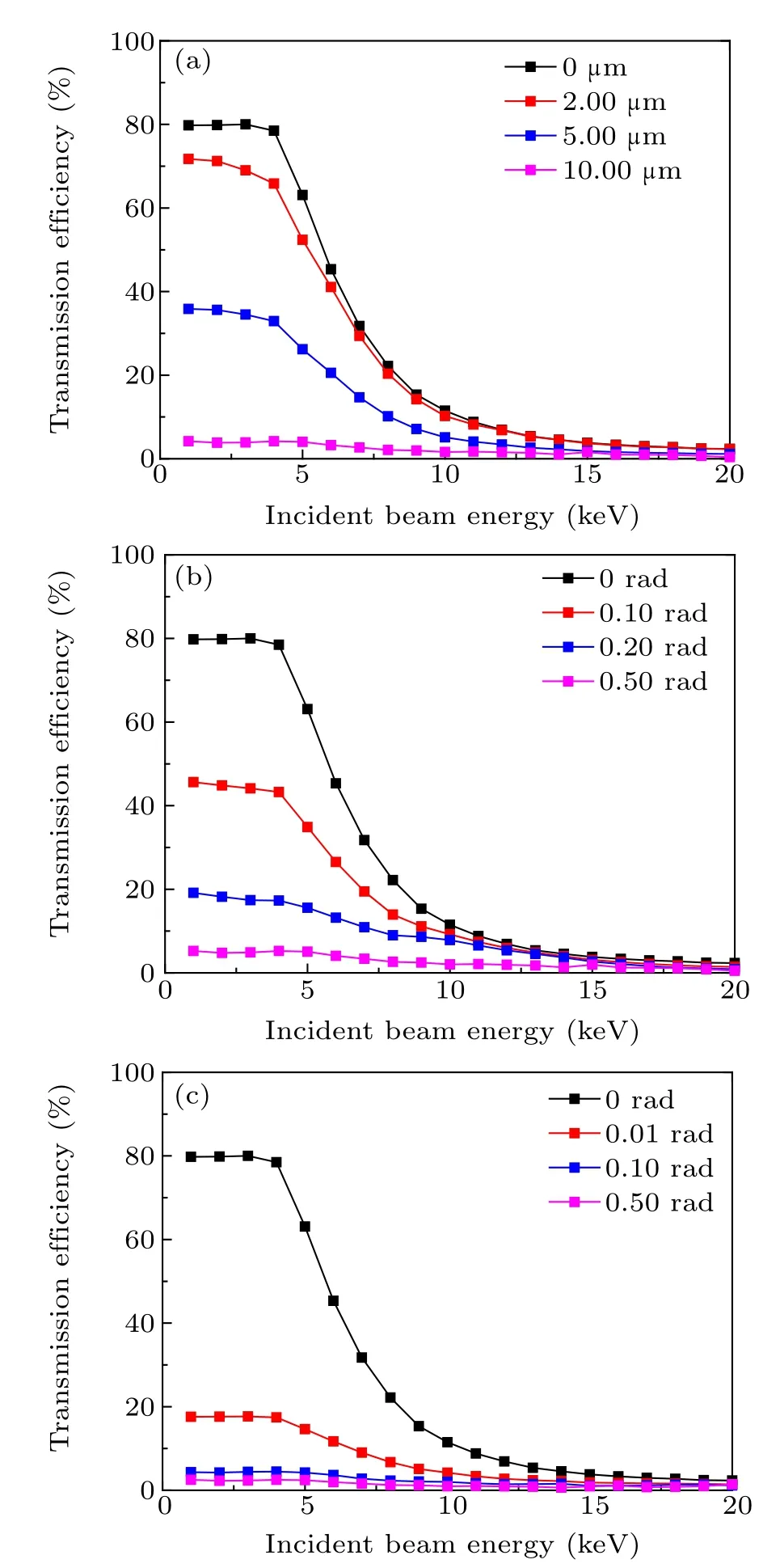
Fig.11.Transmission efficiency versus incident beam energy with:(a)0.00-,2.00-, 5.00-, and 10.00-µm random displacement errors; (b) 0.00-, 0.10-,0.20-, and 0.50-rad transverse axis deviation errors; (c) 0.00-, 0.01-, 0.10-,and 0.50-rad longitudinal axis deviation errors.
As figure 6(a)shows,the focusing quality using ASPXRL was not satisfactory due to the existence of air intervals and manufacturing imperfections.Air intervals leads to the generation of dark stripes and useless background.And manufacturing imperfections would cause distortion of the shape of the focal spot.Figure 9 is a diagram of the two common imperfections:displacement error and axis deviation error.It should be noted that the imperfections of ASPXRL is hard to be measured experimentally.Therefore,simulations were conducted to analyze the cause of the distortion of the focus shape qualitatively.Figure 10 shows the simulation results of the focal spot when different types of imperfections were taken into accounts individually.From Fig.10(a), it can be seen that random displacement error caused shift of the cross arm of the focal spot.Figures 10(b) and 10(c) show that transverse axis deviation errors caused rotation of the cross and longitudinal axis deviation errors caused defocusing directly.These simulated distortions could also be observed in Fig.6(a).The experimental measurement result of the transmission efficiency of ASPXRL is 15% while the design value is 21% at 8.04 keV.To evaluate the effects of the imperfections on focusing capability of ASPXRL, we calculated its transmission efficiency in different conditions.As figure 11 shows, the transmission efficiency of ASPXRL decreases with increasing incident energy in general.At a given incident energy,the decline quantity increases observably with increasing error values.In these three conditions, the effect of the longitude axis deviation error is the most significant.To avoid the potential disadvantages these manufacturing imperfections would bring in,the manufacturing technique should be improved to avoid their generation.This is our next research goal including producing longer square hollow channels which was mentioned above.
4.Conclusion and perspectives
A new type of x-ray lens composed of multi-square polycapillary slices (ASPXRL) used in focusing parallel x-ray beam was presented in this paper.The simulation of the focusing process was based on an improved Monte-Carlo raytracing method.The theory was in good agreement with experiments.Both in simulations and experiments,it suggested that ASPXRL can provide higher focusing quality compared with conventional polycapillary x-ray lens.This is credited to the “cube corner” effect that benefits the family of arrays composed of square channels appears to offer the best focusing performance out of all possible channel cross sections.
However, the current ASPXRL is not perfect.The limitation of manufacturing technique makes the thickness of the slices could not be greater than 3.0 mm.This leads to the existence of air intervals between the slices when assembled.Owing to these intervals,primary incident rays would be misguided and cause the dark stripes and useless background.In addition, manufacturing imperfections such as displacement and axis deviation errors could also affect the focusing quality and make the focal spot aberrated.This is also considered in this work.For difficulty in measurement of ASPXRL in experiments,simulations were conducted to analyze these effects and evaluated using the transmission efficiency.It shows that these imperfections will cause the decrease of the transmission efficiency in general and the effect of longitudinal axis deviation error is the most significant.Thus,our next research goals are longer hollow square channel and less manufacturing imperfections.In summary, it is suggested that ASPXRL can be used to replace conventional polycapillary lens for better focusing performance.This type of lens has application prospects as a condenser lens for x-ray microscopy and flux collectors for x-ray analytical instruments.
Acknowledgment
Project supported by the National Natural Science Foundation of China(Grant No.11875087).
猜你喜欢
杂志排行
Chinese Physics B的其它文章
- A broadband self-powered UV photodetector of a β-Ga2O3/γ-CuI p-n junction
- High-sensitive terahertz detection by parametric up-conversion using nanosecond pulsed laser
- High efficiency,small size,and large bandwidth vertical interlayer waveguide coupler
- High-fidelity resonant tunneling passage in three-waveguide system
- An analytical model for cross-Kerr nonlinearity in a four-level N-type atomic system with Doppler broadening
- Determine the physical mechanism and source region of beat wave modulation by changing the frequency of high-frequency waves
