泵站水力瞬变的二阶Godunov格式模型构建
2022-02-06胡安妮吴金远
周 领,胡安妮,吴金远
泵站水力瞬变的二阶Godunov格式模型构建
周 领1,2,胡安妮1,吴金远1
(1. 河海大学水利水电学院,南京 210098;2. 河海大学长江保护与绿色发展研究院,南京 210098)
为了提高复杂泵站系统水力瞬变数值模拟的高效性和稳定性,该研究基于泵站系统水力瞬变问题,建立有限体积法Godunov格式的数学模型,对简单管道系统和复杂泵站系统进行模拟研究。与常用的特征线法求解泵站水力模型方程不同,该模型引进有限体积法二阶Godunov格式对模型进行离散,用Riemann求解器对离散通量进行求解。使用MUSCL-Hancock方法进行界面数值重构,采用MINMOD斜率限制器避免虚假震荡。提出双虚拟单元边界处理方法,实现计算区域与边界同时达到二阶精度。将所建模型计算结果与精确解、经典算例数据进行对比,并针对库朗数取值和计算网格数进行敏感性分析。结果表明:所建模型模拟结果与精确解、经典算例数据吻合较好;与特征线法相比,二阶Godunov格式更加准确、稳定且高效。对于简单管道系统,特征线法计算耗时0.227 s,二阶Godunov格式计算耗时0.017 s。对于实际泵站系统,由于存在多特性的管道结构,二阶Godunov格式模拟时需稍微降低库朗数。而采用特征线法进行泵站水力过渡过程计算时,若不调整管道长度或者波速,管道中库朗数会小于1,在该文算例中,库朗数为0.72~0.76,模拟计算结果偏差很大。所以需要调整局部管道长度或波速,以达到库朗数为1的条件,这样处理因改变管道特性而引入计算误差。综上,二阶Godunov格式模拟方法可以更有效提高传统泵站系统水力瞬变模拟的高效性、稳定性以及准确性。
泵站;模型;有限体积法;二阶Godunov格式;水力过渡过程;特征线法;一阶Godunov格式
0 引 言
泵站输水系统在启、停机过程因流量变化而发生水力瞬变(或水锤),如果水力控制元件操作或水锤防护设施设置不当,会引起异常的压力波动,从而导致机组损坏、爆管等重大安全事故。准确模拟泵站系统水力瞬变对保证泵站系统安全稳定运行、实现智慧精准化调度运行极为重要[1-4]。
常采用特征线法(Method of Charicteristic, MOC)对泵站系统水力瞬变进行建模模拟[5]。对于简单管道系统,该方法具有简单、准确的优势。然而,在实际工程建设中,泵站系统会存在复杂多特性管道结构,水力计算时,为了满足库朗数为1的稳定计算条件,MOC需要改变局部管段波速、网格长度(管道长度),产生计算误差[5]。
近年来,有限体积法逐渐被用于有压管道水力瞬变计算。Guinot等[6]将有限体积法一阶和二阶格式数值解与精确解进行比对,指出有限体积法可以准确模拟简单管路中水锤压力波动。Zhao等[7]基于Godunov格式(有限体积法的一种数值格式)与Riemann求解器,得到了一阶和二阶的水锤求解格式,并指出Godunov格式可以用于水锤计算,具有较好的准确性和稳定性,但是在边界处理时需要与特征线法相结合。赵越等[8]针对有压管道内水力瞬变问题,采用有限体积法Godunov格式进行一维数学建模,发现一阶Godunov格式与特征线法的计算精度一致,库朗数变化会影响计算精度。Zhou等[9]提出一种基于Godunov格式的二阶显式有限体积法,并将其应用基于特征线法的经典离散空穴模型,发现有限体积法模拟值与试验数据吻合较好,并且可以避免虚假数值震荡。上述研究主要针对简单管道水力瞬变,而实际泵站系统含水泵、阀门、各种特性管道等,水力计算更为复杂。
本文采用有限体积法二阶Godunov格式[10-16]对泵站系统水力过渡过程进行建模,提出将虚拟单元体与水库、水泵等边界元件相结合,通过通量求解模拟管道水锤变化。详细分析了库朗数和计算网格数对MOC方法和有限体积法Godunov格式的数值耗散影响,并采用Chaudhry泵站系统经典算例数据[17]与本文有限体积二阶Godunov格式计算值进行对比。针对某实际泵站系统,对比分析MOC方法和二阶Godunov格式模拟结果。
1 数学模型
1.1 水锤基本控制方程
泵站输水系统中,管道内水锤的基本控制方程[18-22]可由以下连续方程和动量方程进行描述:


式中是测压管水头,m;为沿管轴线方向的长度,m;为时间,s;是水锤波速,m/s;是重力加速度,m/s2;是断面平均流速,m/s;是管道直径,m;是按照Darcy-Weisbach方程求得的摩阻系数。
将水锤基本控制方程(1)~(2)以矩阵形式表示:

采用黎曼求解格式进行求解,将式(3)可改写为常系数双曲方程(4):


1.2 水泵控制方程
1)机组转动方程

式中是机组转动部分加上进入该部分液体的转化惯量,kg·m2;M是电机转矩,N·m;是泵的轴力矩,N·m。
根据机组转动方程式,用泰勒展开作近似变换得到泵的转速平衡方程为

式中、是本时刻机组的转速和力矩相对值;0、0是上一时刻机组的转速和力矩相对值;T为机组的惯性时间常数(s),表示机组在额定轴力矩作用下,额定转速减小到0所需要的时间,表征机组惯性的大小。
2)水头平衡方程

联立机组转动方程(6)和水头平衡方程(8),利用牛顿迭代法可求得水力瞬变过程中每一时刻机组的水头、流量、转速、力矩等参数。
1.3 Godunov求解格式
1.3.1 通量计算
有限体积法将管道离散成若干单元体,每个控制单元内的数值是连续的,但是在两个单元控制单元相交的各个界面处的数值是间断的。采用Godunov格式进行求解时,可通过黎曼问题计算出每个界面上的离散通量,具体如下:


1.3.2 一阶Godunov格式
一阶Godunov格式通过计算单元内变量的平均值来表示界面左右的值:
方程(12)中边界通量由黎曼解确定,先根据黎曼不变量方程对边界处的离散通量进行计算,然后再计算控制单元内的离散通量。通过虚拟边界处理方法,对计算区域内边界和控制单元的离散通量统一模拟。
本文为统一计算整个计算区域的通量值,分别在管道上游边界和管道下游边界加入1个虚拟单元0和虚拟单元+1。
由式(12)以及负向特征线方程可推导出如下的黎曼不变量方程:

由式(12)以及正向特征线方程可推导出如下的黎曼不变量方程:

1.3.3 二阶Godunov格式

1)数据重构


将式(18)代入(17)可以得到:

2)推进时间计算


3)Riemann问题的近似求解

将式(23)~(24)代入式(12)即可得到具有二阶精度的Godunov格式每个计算单元界面+1/2处的数值通量。
1.3.4 虚拟边界
一阶Godunov格式为实现全瞬变区域内的统一模拟,在上下游边界处各加入一个虚拟单元。由于计算精度的提高,二阶Godunov格式需在上游边界处左边和下游边界处的右边分别加入2个虚拟单元0、-1和虚拟单元+1、+2。
对于上游水库:


对于下游水库:


对于泵站机组,将式(29)~(32)代入式(8)中即可求解虚拟边界下的水头平衡方程:


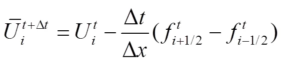
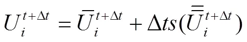
1.3.5 时间积分

一阶Godunov格式通过欧拉法进行,二阶Godunov格式采用具有二阶精度龙格库塔法进行计算,如下:

2 算例分析
2.1 模型验证
2.1.1 简单管道水锤问题
设置一上游为水库,下游为阀门的简单管道。管道长20.0 m,水锤波速为1 319 m/s,上游水库水位为30.0 m,初始流速为0.1 m/s,重力加速度为9.8 m/s2,计算网格数为16,下游阀门设置为瞬时关闭,光滑管道(无摩阻)。图1和图2中精确解是根据水锤基本控制方程[5]求解得到,在上文式(1)~(2)中,无摩阻项时,基本方程变成线性偏微分方程,理论上解析解即精确解[23-27]。则结果中的所有压力衰减均是由于数值耗散引起的。
图1和图2给出了库朗数=0.2、0.6、1.0时,MOC、一阶Godunov格式(First-order Godunov scheme, 1st-order GTS)、二阶Godunov格式(Second-order Godunov scheme, 2nd-order GTS)模拟阀门处水锤计算结果。

图1 不同库朗数条件下水锤压力计算结果(计算网格数Ns=16)
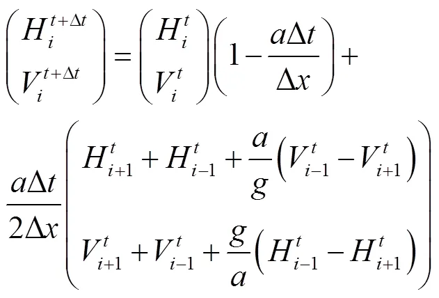
如图1a所示,在=1条件下,MOC方法与一阶Godunov格式模拟结果与精确值完全吻合。当1时,MOC方法与一阶Godunov格式模拟结果精度完全一致,且越小,数值衰减越严重。从数值模型方面分析,两种方法是相似的。MOC模型可写成如下形式:


式中下标代表待求节点,-1代表左边节点,+1代表左边节点。
式(37)~(39)也可写作式(40):

如图1b所示,在=1的条件下,二阶Godunov格式方法模拟结果与精确值完全吻合。在<1时,与MOC和一阶Godunov格式方法相比,二阶Godunov格式能有效抑制数值耗散。
此外,考虑计算网格数对数值模拟结果的影响,如图2所示,增加计算网格数量,使=256,对比不同库朗数条件下MOC方法和二阶Godunov格式数值耗散程度。

图2 不同库朗数条件下水锤压力计算结果(计算网格数Ns=256)
如图2所示,对于MOC方法,适当增加计算网格数对计算结果影响很大,网格数的增加会使数值耗散减小。对于二阶Godunov格式,计算网格数的影响较小。同样库朗数情况下,二阶Godunov格式下稀疏网格(=16)的模拟结果与MOC方法网格加密后(=256)的模拟结果基本一致。在相同精度要求下,=256时,MOC的计算耗时0.227 s,二阶Godunov格式(=16)计算耗时0.017 s。这说明二阶Godunov格式效率更高。
2.1.2 泵站系统水力瞬变模拟验证
为验证水泵模型的准确性,本文模型计算值与Chaudhry[17]经典数据(被学者们广泛用于仿真模型验证)进行对比。水泵系统包括2台水泵,阀门,上下游水库。水泵采用并联,水泵直接与上游水库相连。2台泵的参数一致:水泵中液体的综合转动惯量2=16.85,额定效率η=0.84,额定转速N=1 100 r/min,额定流量Q=0.25 m3/s,额定扬程H=60 m。管道参数如表1所示。

表1 Chaudhry算例的管道参数[17]
采用特征线法对该系统进行水力分析,水泵转速、流量以及水泵出口水头计算结果如表2所示。
如表2所示,本文提出的二阶Godunov格式和已有常用的特征线法进行水泵失电工况计算。与Chaudhry[17]计算结果对比(图3),水泵流量峰值均为0.25 m3/s;水泵转速峰值均为1 100 r/min;水泵扬程峰值均为87 m。泵转速、流量、压力的最小值也基本吻合。因此,本文所建立的二阶Godunov格式模型能准确模拟泵站系统水力瞬变。
2.2 复杂泵站系统瞬态计算
2.2.1 泵站参数
某泵站系统设置4台设计轴功率为3 500 kW的水泵机组,采用“2用2备”运行方式,水库1水位6.4 m,水库2水位3.15 m。2台泵的参数一致:设计扬程=52.7 m,设计流量=5.0 m3/s,额定转速=500 r/min,转动惯量2=14.5 t·m2,设计轴功率=3 500 kW。布置方式如图4所示,管道参数如表3所示。

图3 Chaudhry泵站算例计算结果

图4 某泵站系统示意图
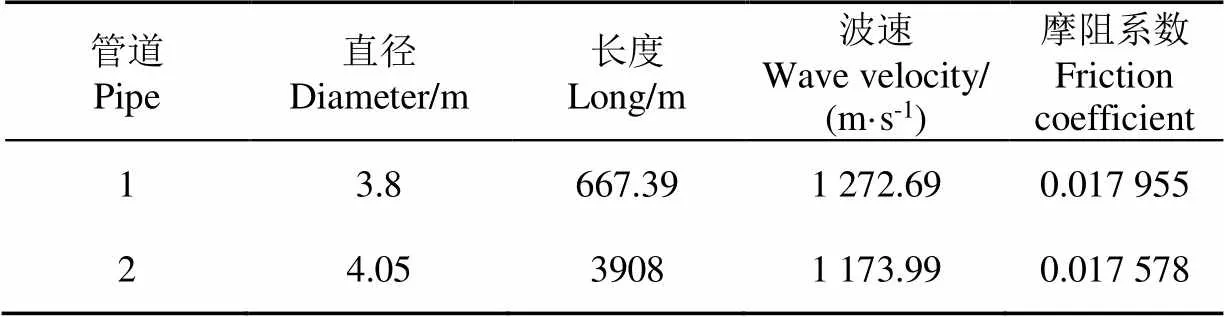
表3 泵站系统管道参数
2.2.2 计算结果
针对泵机组失电工况进行计算分析,采用两阶段关阀规律[28-30],快关时间30 s,总关阀时间90 s,拐点处阀门开度为0.166 7。实际泵站系统水力计算时,MOC一般采用调整各管道水锤波速,以保证库朗数为1(计算方案1:Case1);另外也可采用保持各管道水锤波速不变,库朗数小于1(计算方案2:Case2)。
本文主要计算库朗数变化对MOC方法、二阶Godunov格式数值耗散的影响,以及2种计算方案对计算结果的影响,相应库朗数取值见表4。
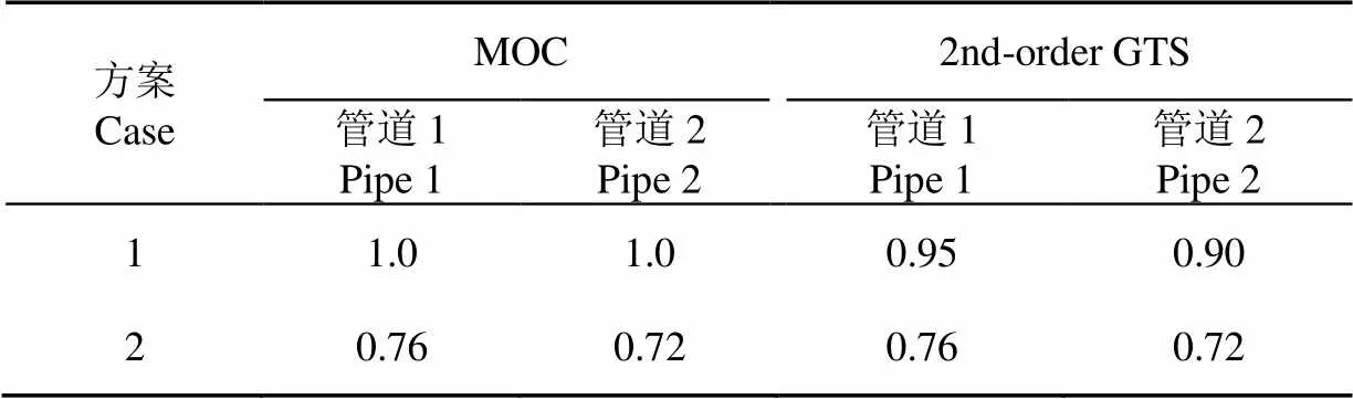
表4 两种计算方案Cr取值
如表5所示,方案1中MOC方法对管道波速进行调整,二阶Godunov格式方法管道波速取原值。方案1管道系统参数见表5。
2种方法模拟泵站系统发生失电后120 s水力瞬变过程。整个计算时段内水泵最大反转转速、最大倒流流量、水泵出口阀后最小压力、水泵出口阀后最大压力见表6所示。

表5 计算方案1中管道系统参数处理
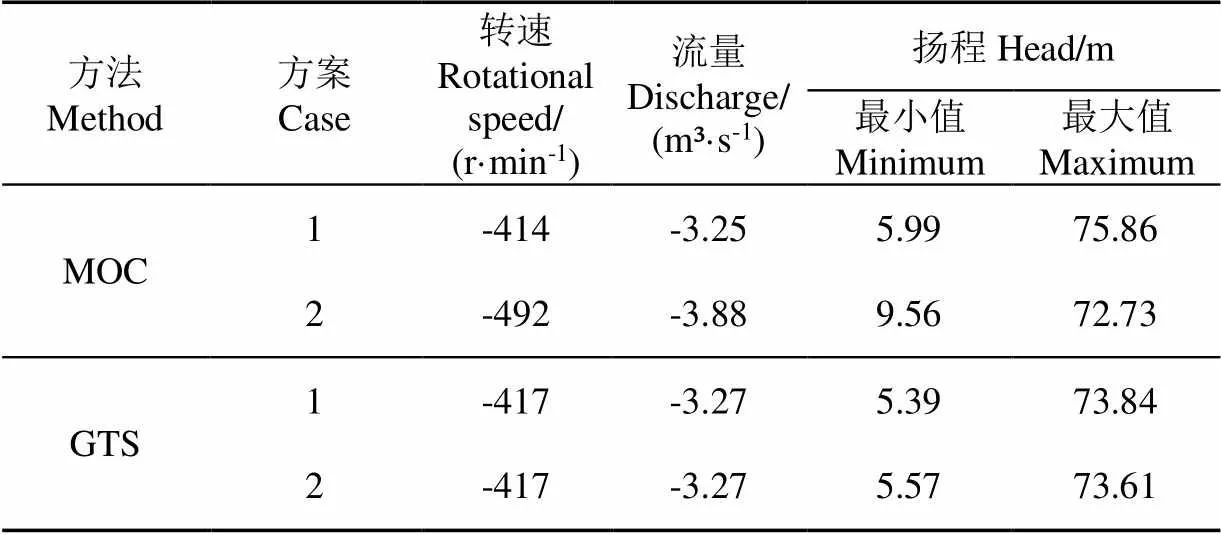
表6 两种计算方案下不同计算方法的计算结果
如表6所示,在实际泵站系统中,库朗数条件的变化对于二阶Godunov格式模拟结果影响很小,水泵最大反转转速稳定在−417 r/min,水泵最大倒流流量稳定在−3.27 m³/s,扬程峰值变化范围很小,这说明二阶Godunov格式模拟结果稳定,这与简单管道结论一致。然而,对于MOC方法,方案1的管道波速经调整后,均高于实际管道波速,故水泵出口阀后压力峰值增大,而方案2采用管道实际波速,扬程峰值减小3.13 m,倒流流量变化至−3.88 m3/s,库朗数条件的变化使水泵最大反转转速、最大倒流流量、水泵出口阀后最大、最小压力的峰值和周期均出现较大误差。因此对于水泵系统水力瞬变模拟,本文采用的二阶Godunov格式更具有稳定性、准确性。机组转速、流量、水泵出口阀后压力变化过程线见图5。

图5 泵站系统计算结果
为考虑网格数对计算结果的影响,在上文2个算例基础上设置方案3和方案 4,参数设置如表7所示。
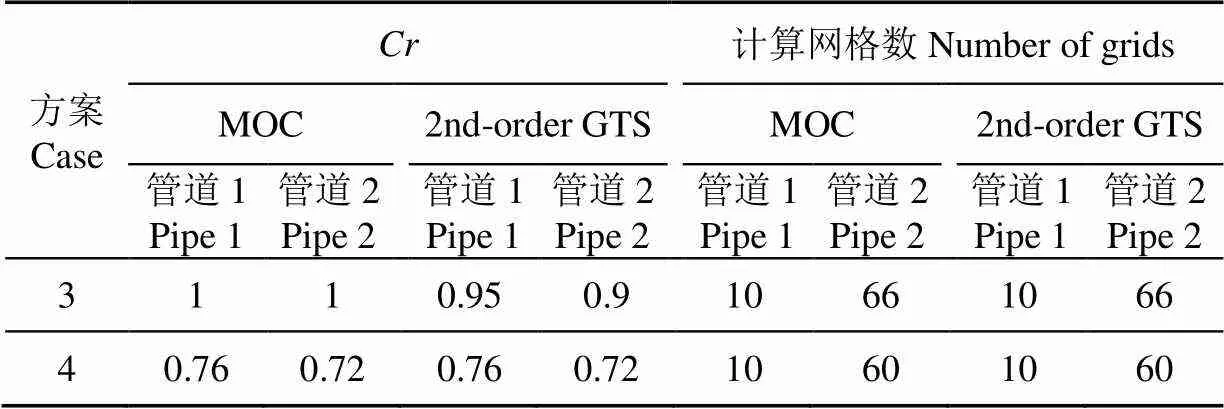
表7 方案3、4的参数设置
如图6a所示,对于MOC方法,库朗数小于1时,增加网格数可以适当提高计算结果精确度,但是计算耗时将成倍增加(MOC中Case2和Case4的计算耗时分别为0.063和0.094 s)。如图6b所示,对于二阶Godunov格式,库朗数等于或小于1,网格数对计算结果精确度影响均很小,但计算耗时会增大(二阶Godunov中Case2和Case4的计算耗时分别为0.077 和0.109 s)。因此,当模拟水泵系统瞬变过程面临库朗数小于1情况,为达到相同精度要求,MOC需要更精细网格,其计算耗时将大于二阶Godunov格式。

图6 泵站系统水泵转速模拟结果
3 结 论
本文采用有限体积法二阶Godunov格式对泵站系统水力瞬变进行建模模拟,管道边界采用虚拟边界的处理方法,水力元件边界采用传统的特征线法进行处理。将数值模拟结果与MOC计算所得结果进行对比分析。主要结论:
1)本文建立的二阶Godunov格式可以准确模拟水泵系统水力瞬变过程中水泵转速、流量、压力等参数变化过程线。通过与已有文献计算结果对比可知,本文建立模型模拟结果精确,水泵流量峰值均为0.25 m3/s;水泵转速峰值均为1 100 r/min;水泵扬程峰值均为87 m。泵转速、流量、压力的最小值也基本吻合。
2)与MOC模型相比,二阶Godunov模型具有更好的稳定性、准确性以及高效性。当库朗数<1时,二阶Godunov格式能保持较高的计算精度、结果稳定性。简单管道系统中,在相同精度要求下,同一台计算机中特征线法计算耗时是0.227 s,二阶Godunov格式计算耗时是0.017 s。复杂泵站系统,相同精度要求下,MOC计算耗时在二阶Godunov格式基础上成倍增加,二阶Godunov格式计算效率更高。
3)在实际泵站系统中,为避免数值耗散,MOC模型需要对管道波速和管道分段进行前处理,例如调整波速或者网格长度,或者直接忽略短管,这样处理不仅繁琐,而且因改变管道特性而引入计算误差。对于有限体积法二阶Godunov格式,管道波速或者管道分段无需调整,因为库朗数变化对于二阶Godunov格式模拟结果影响很小。在本文实际算例中,水泵最大反转转速稳定在−417 r/min,水泵最大倒流流量稳定在−3.27 m³/s,扬程峰值变化范围很小,这说明二阶Godunov格式模拟结果稳定。既简单方便,又可保证计算精度。
[1] 刘金昊,吴建华. 西山供水工程事故停泵水力过渡过程计算及水锤防护[J]. 水电能源科学,2021,39(7):113-116.
Liu Jinhao, Wu Jianhua. Calculation of hydraulic transition process and water hammer protection for accidental pump-stop in xishan water supply project [J]. Water Resources and Power, 2021, 39(7): 113-116. (in Chinese with English abstract)
[2] 黄伟,杨开林,郭新蕾,等. 抽水蓄能电站极端甩负荷工况球阀协同调节[J]. 清华大学学报(自然科学版),2019,59(8):635-644.
Huang Wei, Yang Kailin, Guo Xinlei, et al. Coordinated regulation of ball valves in pumped storage stations for extreme conditions[J]. Journal of Tsinghua University (Science & Technology), 2019, 59(8): 635-644. (in Chinese with English abstract)
[3] 杨玉思,徐艳艳,羡巨智. 长距离高扬程多起伏输水管道水锤防护的研究[J]. 给水排水,2009,45(4):108-211.
Yang Yusi, Xu Yanyan, Xian Juzhi. Research on water hammer prevention in high lift, hilly and long distance water transmission pipeline[J]. Water & Wastewater Engineering, 2009, 45(4): 108-211. (in Chinese with English abstract)
[4] 方永,周宏. 管道系统中的水锤及其防护研究[J]. 石化技术,2016,23(2):115.
Fang Yong, Zhou Hong. Water hammer and preventive measures in pipeline[J]. Petrochemical Industry Technology, 2016, 23(2): 115. (in Chinese with English abstract)
[5] Wylie E B, Streeter V L, Suo L. Fluid transients in systems[M]. Englewood Cliffs, NJ: Prentice Hall, 1993.
[6] Guinot V. Riemann solvers for water hammer simulations by Godunov method[J]. International Journal for Numerical Methods in Engineering, 2000, 49(7): 851-870.
[7] Zhao M, Ghidaoui M S. Godunov-type solutions for water hammer flows[J]. Journal of Hydraulic Engineering-ASCE, 2004, 130(4): 341-348.
[8] 赵越,周领,刘德有,等. 基于有限体积法Godunov格式的水锤计算模型[J]. 水利水电科技进展,2019,39(1):76-81.
Zhao Yue, Zhou Ling, Liu Deyou, et al. Water hammer model based on finite volume method and Godunov-type scheme[J]. Advances in Science and Technology of Water Resources. 2019, 39(1): 76-81. (in Chinese with English abstract)
[9] Zhou L, Wang H, Liu D Y, et al. A second-order finite volume method for pipe flow with water column separation [J]. Journal of Hydro-environment Research, 2016, 17: 47-55.
[10] 向小华,吴晓玲,牛帅,等. 基于显式有限体积法的一维河网模型[J]. 水利水电科技进展,2015,35(4):6-9,43.
Xiang Xiaohua, Wu Xiaoling, Niu Shuai, et al. Construction of one-dimensional river network model based on explicit finite volume method[J]. Advances in Science and Technology of Water Resources, 2015, 35(4): 6-9, 43. (in Chinese with English abstract)
[11] Hu Y Y, Zhou L, Pan T W, et al. Godunov-type solutions for free surface transient flow in pipeline incorporating unsteady friction[J]. Journal of Water Supply: Research and Technology-Aqua, 2022, 71(4): 546-562.
[12] 郑劼恒,蒋明,郭芮,等.顺序输送管道水力瞬变模拟的有限体积法[J]. 计算力学学报,2015,32(3):418-422,428.
Zheng Jieheng, Jiang Ming, Guo Rui, et al. Finite volume method for hydraulic transient simulation of batching pipeline[J]. Chinese Journal of Computational Mechanics, 2015, 32(3): 418-422, 428. (in Chinese with English abstract)
[13] 杨开林. 电站与泵站中的水力瞬变及调节[M]. 北京:中国水利水电出版社,2000.
[14] Toro E F. Riemann solvers and numerical methods for fluid dynamics[M]. Berlin: Verlag Berlin Heidelberg, 2009: 115-125.
[15] 刘锦涛,章少辉,许迪,等. 灌溉输配水系统明满流的全隐式耦合模拟及验证[J]. 农业工程学报,2017,33(19):124-130.
Liu Jintao, Zhang Shaohui, Xu Di, et al. Coupled simulation and validation with fully implicit time scheme for free-surface-pressurized water flow in pipe/channel[J]. Transactions of the Chinese Society of Agricultural Engineering(Transactions of the CSAE), 2017, 33(19): 124-130. (in Chinese with English abstract)
[16] 王振华,马习贺,李文昊,等.基于改进4-方程摩擦模型的输水管道水锤压力计算[J]. 农业工程学报,2018,34(7):114-120.
Wang Zhenhua, Ma Xihe, Li Wenhao, et al. Calculation of water hammer pressure of flow pipeline based on modified four-equation friction model[J]. Transactions of the Chinese Society of Agricultural Engineering(Transactions of the CSAE), 2018, 34(7): 114-120. (in Chinese with English abstract)
[17] Chaudhry M H. 实用水力瞬变过程[M]. 北京:中国水利水电出版社,2015.
[18] Lyu J W, Zhang J, Wang T Y. Study on water hammer protection of the siphon breaking structure in the water supply system[J]. AQUA-Water Infrastructure, Ecosystems and Society, 2022, 71(3): 478-489.
[19] Abdel-Fatah M A, Amin A, Al Bazedi G A. Model and protected design of water piping system to minimize the water hammer effect[J]. Egyptian Journal of Chemistry, 2022, 65(1): 1-2.
[20] Lupa S I, Gagnon M, Muntean S, et al. The impact of water hammer on hydraulic power units[J]. Energies, 2022, 15(4): 1526.
[21] 富友,蒋劲,李燕辉,等. 改进双流体模型计算有液柱分离的管路水锤压力[J]. 农业工程学报,2018,34(15):58-65.
Fu You, Jiang Jing, Li Yanhui, et al. Calculation of pipe water hammer pressure with liquid column separation by improved two-fluid model[J]. Transactions of the Chinese Society of Agricultural Engineering(Transactions of the CSAE), 2018, 34(15): 58-65. (in Chinese with English abstract)
[22] 周领,陆燕清.排水管道瞬变流的SWMM模拟能力研究[J]. 中国给水排水,2022,38(5):108-115.
Zhou Ling, Lu Yanqing. SWMM simulation capability for transient fow in drainage pipe[J]. Water & Wastewater Engineering, 2022, 38(5): 108-115. (in Chinese with English abstract)
[23] 吴峰. 输水管道中含气水流瞬变特性试验研究及数值模拟[D]. 西安:西安理工大学,2021.
Wu Feng. Experimental Research and Numerical Simulation on Transient Characteristics of Air-Bearing Water Flow in Water Pipeline[D]. Xi’an: Xi’an University of Technology, 2021. (in Chinese with English abstract)
[24] 丁泽. 有压管道中阀门工作状态检测研究[D]. 哈尔滨:哈尔滨商业大学,2019.
Ding Ze. Research on Valve Working State Detection in Pressurized Pipeline[D]. Harbin: Harbin University of Commerce, 2019. (in Chinese with English abstract)
[25] 赵思茂. 输水管道内瞬变流特性的三维数值模拟研究[D]. 西安:西安理工大学,2020.
Zhao Simao. Three Dimensional Numerical Simulation of Transient Flow in Water Pipeline[D]. Xi’an: Xi’an University of Technology, 2020. (in Chinese with English abstract)
[26] Al-Khayat R H, Kadhim A A, Al-Baghdadi M A R S, et al. Flow parameters effect on water hammer stability in hydraulic system by using state-space method[J]. Open Engineering, 2022, 12(1): 215-226.
[27] Waqar M, Louati M, Ghidaoui M S. Time-reversal of water-hammer waves[J]. Journal of Hydraulic Research, 2022, 60(1): 25-45.
[28] Li Y J, Hu X D, Zhou F J, et al. A new comprehensive filtering model for pump shut-in water hammer pressure wave signals during hydraulic fracturing[J]. Journal of Petroleum Science and Engineering, 2022, 208: 109796.
[29] Kim S G, Lee K B, Kim K Y. Water hammer in the pump-rising pipeline system with an air chamber[J]. Journal of Hydrodynamics, 2014, 26(6): 960-964.
[30] Wan W Y, Li F Q. Sensitivity analysis of operational time differences for a pump-valve system on a water hammer response[J]. Journal of Pressure Vessel Technology, 2016, 138(1): 011303.
Construction of the second-order Godunov scheme model for hydraulic transients in pumping stations
Zhou Ling1,2, Hu Anni1, Wu Jinyuan1
(1.,,210098,; 2.,,210098,)
This study aims to implement a more efficient and stable numerical simulation of the hydraulic transient in a complex pumping station system. A finite volume method (FVM) Godunov scheme was established to simulate the simple pipeline and complex pumping station system. The FVM was then introduced to discretize the mathematical models, while the Riemann solver was selected to solve the discrete flux. The MUSCL-Hancock method was utilized to reconstruct the numerical data at the interface of control volumes. The higher numerical accuracy and stability were realized in the Godunov scheme, compared with the frequently-used method of characteristics. Meanwhile, the MINMOD slope limiter was used to avoid false oscillation. The boundary processing of the dual virtual unit was then presented for the second-order accuracy of both the computational region and the boundary, particularly for the simpler computation. The simulation of the improved model was in good agreement with the exact solution and the classical examples. The sensitivity analysis was also performed on the Courant and grid number. Furthermore, a more accurate, stable, and efficient performance was achieved in the second-order Godunov scheme, compared with the method of characteristics. More importantly, there was more outstanding attenuation with the decrease of the Courant number for a simple pipeline system. The computation time of the second-order Godunov scheme was 0.017 s at the same accuracy, compared with the method of characteristics (0.227 s). Consequently, a more stable and efficient performance was achieved in the second-order Godunov scheme. In the actual pumping system with the multiple-characteristics pipe structure, the second-order Godunov scheme required only a slight reduction in the Courant numbers, indicating the simple and convenient way for high numerical accuracy. Once the method of characteristics was used to calculate the hydraulic transition of the pumping station, the Courant number in the pipeline was less than 1 at the same length or wave velocity of the pipeline. By contrast, the Courant number was 0.72-0.76 in this case, indicating a very different simulation from the actual. Therefore, it is necessary to adjust the local pipeline length or wave velocity for the condition that the Courant number was 1. The tedious operation can lead to calculation errors, due to the change in pipeline characteristics. The accuracy can be improved but with less computational efficiency, if the wave velocity remained unchanged to increase the number of computational grids. In the method of characteristics, the number of grids can properly improve the accuracy of the calculation but with the doubled computation time, when the Courant number was less than 1. In the second-order Godunov scheme, there was little effect of grid number on the accuracy of the calculation but with the longer calculation time, whether the Courant number was equal to or less than 1. Therefore, a finer grid was preferred in the method of characteristics for the same accuracy requirements, when the Courant number was less than 1 in the transient process of the simulated pump system. Therefore, the second-order Godunov scheme can accurately simulate the process lines of rotational speed, discharge, and outlet pressure parameters during the hydraulic transient of the pump system. Anyway, the second-order Godunov scheme can be expected to effectively improve the efficiency, stability, and accuracy of hydraulic transient simulation of traditional pumping station systems.
pump station; models; finite volume method; second-order Godunov scheme; hydraulic transition process; method of characteristics; first-order Godunov scheme
10.11975/j.issn.1002-6819.2022.19.005
TV143.1
A
1002-6819(2022)-19-0042-09
周领,胡安妮,吴金远. 泵站水力瞬变的二阶Godunov格式模型构建[J]. 农业工程学报,2022,38(19):42-50.doi:10.11975/j.issn.1002-6819.2022.19.005 http://www.tcsae.org
Zhou Ling, Hu Anni, Wu Jinyuan. Construction of the second-order Godunov scheme model for hydraulic transients in pumping stations[J]. Transactions of the Chinese Society of Agricultural Engineering (Transactions of the CSAE), 2022, 38(19): 42-50. (in Chinese with English abstract) doi:10.11975/j.issn.1002-6819.2022.19.005 http://www.tcsae.org
2022-05-12
2022-08-24
国家自然科学基金项目(51679066,51839008);霍英东教育基金会青年教师基金(161068)
周领,博士,教授,研究方向为水电站、泵站、输水工程水力学。Email:zlhhu@163.com
