Analysis of large deformation geotechnical problems using implicit generalized interpolation material point method*
2021-11-21WeihaiYUANHaochengWANGKangLIUWeiZHANGDingWANGYuanWANG
Wei-hai YUAN, Hao-cheng WANG, Kang LIU, Wei ZHANG, Ding WANG, Yuan WANG
Analysis of large deformation geotechnical problems using implicit generalized interpolation material point method*
Wei-hai YUAN1, Hao-cheng WANG1, Kang LIU2, Wei ZHANG†‡3, Ding WANG4, Yuan WANG5
University, Nanjing 210098, China School of Civil Engineering, Hefei University of Technology, Hefei 230009, China College of Water Conservancy and Civil Engineering, South China Agricultural University, Guangzhou 510642, China Hunan Provincial Water Transportation Construction & Investment Group Co., Ltd., Changsha 410200, China College of Water Conservancy and Hydropower, Hohai University, Nanjing 210098, China †E-mail: zhangwei@scau.edu.cn
This paper presents a quasi-static implicit generalized interpolation material point method (iGIMP) with B-bar approach for large deformation geotechnical problems. The iGIMP algorithm is an extension of the implicit material point method (iMPM). The global stiffness matrix is formed explicitly and the Newton-Raphson iterative method is used to solve the equilibrium equations. Where possible, the implementation procedure closely follows standard finite element method (FEM) approaches to allow easy conversion of other FEM codes. The generalized interpolation function is assigned to eliminate the inherent cell crossing noise within conventional MPM. For the first time, the B-bar approach is used to overcome volumetric locking in standard GIMP method for near-incompressible non-linear geomechanics. The proposed iGIMP was tested and compared with iMPM and analytical solutions via a 1D column compression problem. Results highlighted the superiority of the iGIMP approach in reducing stress oscillations, thereby improving computational accuracy. Then, elasto-plastic slope stabilities and rigid footing problems were considered, further illustrating the ability of the proposed method to overcome volumetric locking due to incompressibility. Results showed that the proposed iGIMP with B-bar approach can be used to simulate geotechnical problems with large deformations.
Material point method (MPM); Large deformation; Implicit generalized interpolation material point method (iGIMP); Volumetric locking; B-bar method
1 Introduction
The material point method (MPM) originated from the particle-in-cell method in fluid mechanics, and was first developed and applied to solid mechanics by Sulsky et al. (1994). MPM shows great potential in simulating large deformation problems and therefore has attracted the interest of researchers from different fields for many years. MPM has been successfully applied in various applications, including granular flows (Bardenhagen et al., 2000; Cummins and Brackbill, 2002; Coetzee, 2004), impact problem (Huang et al., 2011; Li et al., 2011, 2014), metal forming (Lemiale et al., 2010), sea ice models (Sulsky et al., 2007), and mechanics of cells (Guilkey et al., 2006), and more recently has been applied in the geotechnical field (Wiȩckowski, 2004; Coetzee et al., 2005; Beuth et al., 2011; Bandara and Soga, 2015; Sołowski and Sloan, 2015; Yerro et al., 2015; Soga et al., 2016; Wang et al., 2016a, 2016b; Zhao et al., 2021).
MPM divides a continuum body into a set of Lagrangian particles, i.e. material points, which are tracked during the computation process. The information of the continuum is associated with each material point rather than the grid nodes. In MPM, a separate Eulerian grid (background mesh) is used to solve the governing equations. This is in contrast to other mesh-free methods where the governing equations are solved on the particles. As the background mesh carries no permanent information, it can be reset to its initial position, or other positions for the convenience of computation, after each time/loading step. Therefore, the mesh distortions that may occur when simulating large deformations in standard finite element method (FEM) are avoided. By using this mixed Lagrangian-Eulerian formulation, MPM combines the advantages of both Eulerian and Lagrangian formulations (Beuth et al., 2011).
Despite some advantages in dealing with large deformations in solid mechanics, the traditional MPM with low-order shape functions suffers from so-called cell crossing instabilities. As the material points cross a cell boundary, the gradients of the interpolation functions result in discontinuities between elements, which cause discontinuities in the stress calculation. In severe cases, this can abruptly terminate the simulation. Thus, many efforts have been conducted to improve the stress performance. Bardenhagen and Kober (2004) proposed the so-called generalized interpolation material point (GIMP) method, in which each material point is assigned a domain and a characteristic function is introduced in formulating the interpolation basis functions. In this way, the GIMP method can reduce the cell crossing instabilities as it provides extra degree of smoothness to the solution.
It is well-known that incompressible material behaviour or undrained conditions may lead to volumetric locking of the low-order elements in the FEM. MPM suffers from the same issue since low-order elements are typically used. Volumetric locking introduces a spurious increase in stiffness and numerical oscillations, which eventually lead to numerical instability. To overcome the volumetric locking issue, various approaches have been developed in MPM. These include the use of higher-order interpolation functions (i.e. B-spline functions) (Steffen et al., 2008), mixed displacement-pressure formulations (Iaconeta et al., 2019), the B-bar approach (Bandara and Soga, 2015; Wang et al., 2018), the F-bar approach (Coombs et al., 2018), the fractional step method (Jassim et al., 2013; Yamaguchi et al., 2020), the reduced integration method (Abe et al., 2014), and the enhanced volumetric strain approach (Jassim et al., 2013).
Note that the GIMP method cannot overcome the volumetric locking issue; thus, many solutions have been proposed to solve this problem. For example, Mast et al. (2012) adopted the Hu–Washizu multi-field method which applies a smoothing approach on deviatoric and volumetric components of the strain and stress fields. An F-bar approach was applied in quasi-static GIMP by Coombs et al. (2018). Although these approaches have been shown to overcome volumetric locking in GIMP, the Hu–Washizu multi-field method introduces additional non-physical smoothing approaches, and the F-bar method needs additional linearization to the stiffness matrix. Both approaches add significant complexity to GIMP.
MPM has so far been solved mostly using explicit time integration schemes. Thus, the time step size is limited by the Courant-Friedrichs-Lewy (CFL) condition (Yuan et al., 2019, 2020; Zhang et al., 2021). Moreover, for two-phase dynamic explicit formulation in MPM, the time step size is also limited by permeability (i.e. the critical time step size decreases with permeability) (Mieremet et al., 2016; Zheng et al., 2021). Meanwhile, the use of explicit time integration may results in inaccuracy for elasto-plastic problems. Moreover, errors may accumulate over time. Increasing the number of sub-increments can improve accuracy, but the computational cost may then become unacceptable. Therefore, many implicit MPM formulations have been proposed. Cummins and Brackbill (2002) proposed a matrix-free implicit-MPM method to simulate the quasi-static loading of granular materials. Sulsky and Kaul (2004) developed a similar framework of MPM and discussed three Newton–Krylov solvers for numerical efficiency. Later, Nair and Roy (2012) extended this implicit algorithm to the GIMP method. In contrast, Guilkey and Weiss (2003) explicitly formed the tangent stiffness matrix, and solved the discretized governing equations using the Newton-Raphson method. Beuth et al. (2011) proposed an MPM implementation to simulate quasi-static problems using an implicit integration scheme. More recently, Wang et al. (2016c) provided a quasi-static and dynamic implicit MPM framework. Charlton et al. (2017) and Coombs et al. (2018) proposed an implicit GIMP method for large deformations.
In this paper, a quasi-staticimplicit generalized interpolation material point method (iGIMP)framework is proposed by combining the GIMP interpolation function, the B-bar approach, and the implicit integration scheme. The quasi-static iGIMP with B-bar scheme is computationally efficient and can greatly reduce cell crossing errors and volumetric locking, thereby improving the accuracy of the algorithm. The rest of this paper is organized as follows: in Section 2, a brief introduction to the iGIMP formulations is presented. In Section 3, the proposed approach is validated and thoroughly compared with implicit material point method (iMPM) and iGIMP via a 1D column compression problem, and then two slope failure problems and a rigid footing problem are used to further highlight the advantages and capabilities of the proposed approach in modeling large deformation geotechnical applications.
2 Governing equations of the quasi-static problem
2.1 Mechanical equilibrium equations
In the update Lagrangian (UL) formulation, all variables must be transferred to the current geometrical configuration of the continuum to solve the mechanical equilibrium equation. So the equilibrium equation for a deformable body of volumeVat time+∆, bounded by surfaceS, can be written in its weak form as (Bathe, 1996; Wang et al., 2016c)
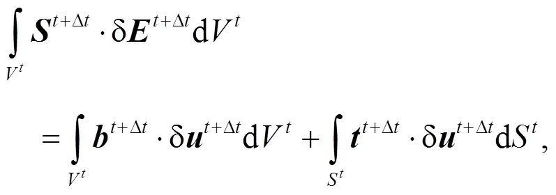
whereis the second Piola-Kirchhoff (PK2) stress tensor,is the Green–Lagrange strain tensor, δis the virtual displacement, andandare body forces and boundary tractions, respectively. Using the last known configuration at timeas a reference, the PK2 stress tensor can be expressed in the incremental form as

whereis the Cauchy stress.
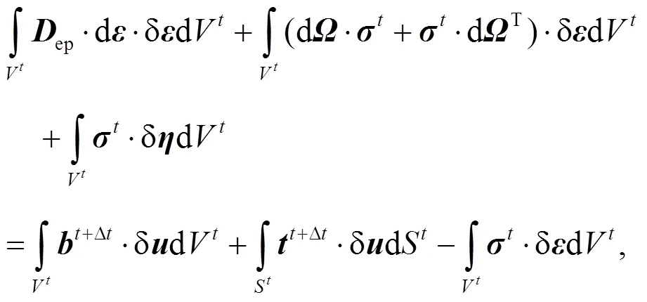
By considering the frame-independent Jaumann stress rate, and ignoring the high-order terms, the linearized governing equation for equilibrium is obtained as

2.2 Spatial discretization for MPM
For a quantitative solution, Eq. (3) is discretized in space by finite elements using the Galerkin procedure. By introducing the shape functions, the following system of equilibrium equations in matrix form can be obtained as

whereis the global stiffness matrix,is the residual vector, and the subscriptindicates the iteration number. Due to material and geometric nonlinearity, this equation must be solved using the Newton-Raphson method, and the iterative updating scheme is
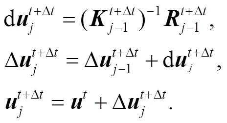
Note that the nodal coordinates are reset to the initial position after each time/load step in the MPM approach.
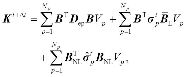
In MPM, the weak form is integrated at the material points instead of Gauss points. For example, the material point based integration of the material stiffness matrix yields



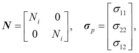

2.3 Generalized interpolation material point method
In the GIMP method, a general characteristic functionχis chosen to replace the Dirac delta in the original MPM, and the shape functionScan thus be defined by the convolution of the characteristic functionχand the grid shape functionNas

The choosing of these two functions is in general arbitrary, while in practice, the tent-shaped grid functionNis usually used in typical GIMP as
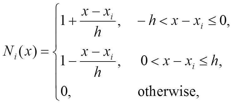
wherexis the node location anddenotes the cell spacing. The simplest choice of 1D particle characteristic function is taken as

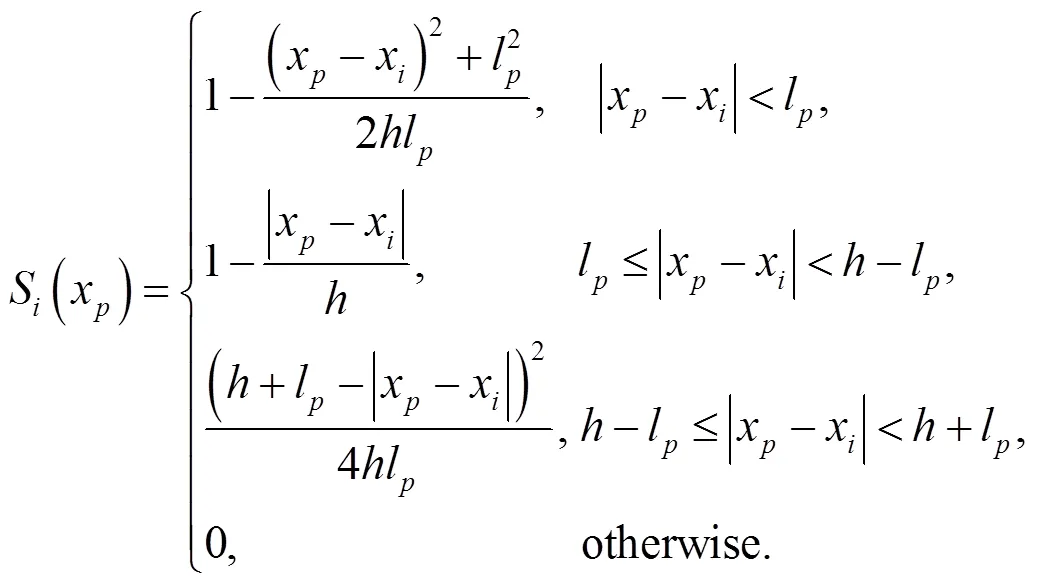
where lis the half length of the particle. The initial particle length is determined by dividing the cell spacing by the number of particles per cell. The GIMP shape function can be written as (Bardenhagen and Kober, 2004):
The space derivative of the GIMP shape function is given as
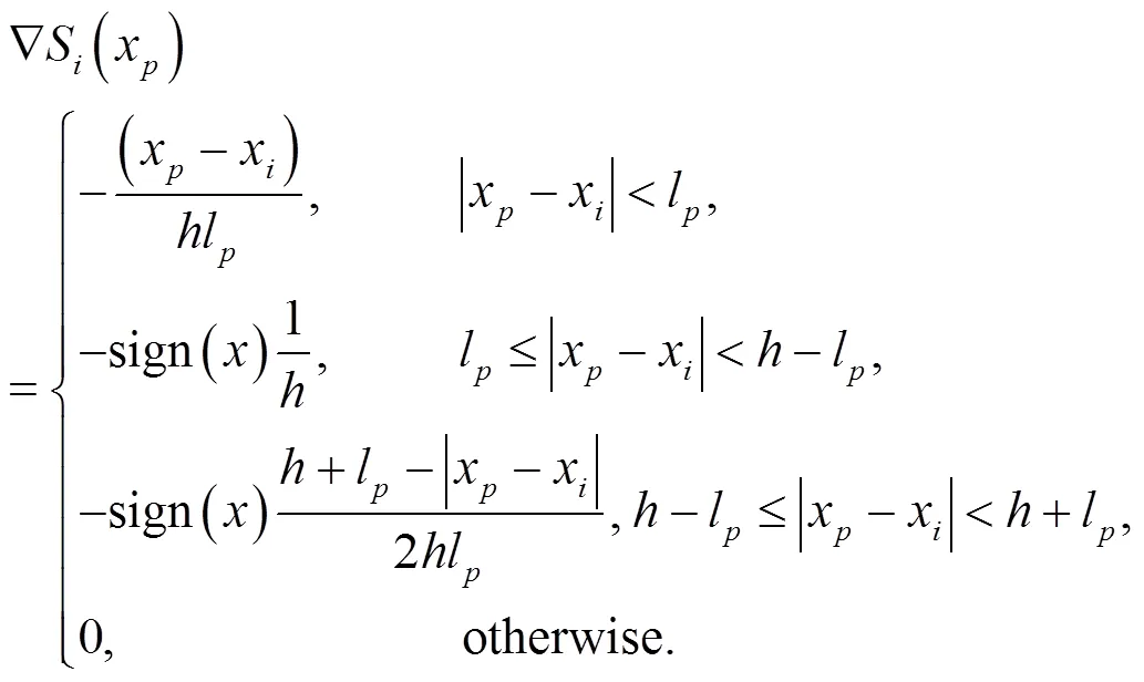
Examples of the GIMP shape function and space derivatives of the shape function are given in Fig. 1. In multi-dimensional problems, the GIMP shape functions are constructed based on the 1D shape functions, e.g.S(,)=S()S() for 2D problems.
2.4 Mitigating volumetric locking in GIMP

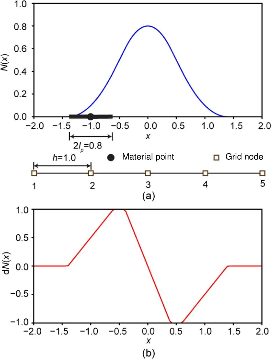
Fig. 1 Typical GIMP shape function (a) and space derivative of the shape function (b)

whereis the nodal displacement vector, in which


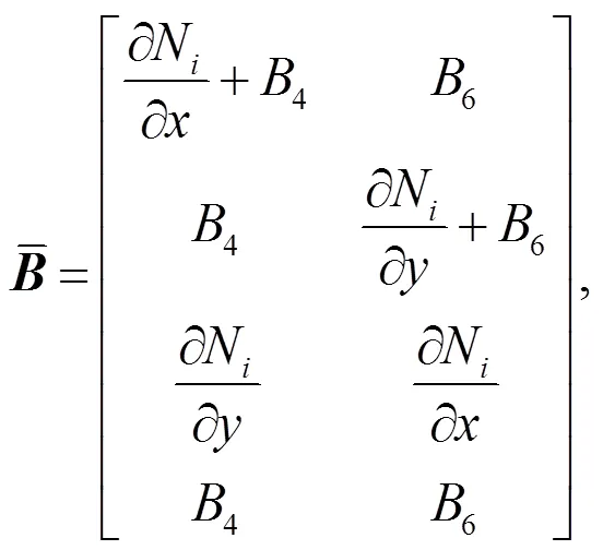

Although the B-bar method has been successfully used in standard MPM, this is the first time it has been extended to the iGIMP method. For the standard MPM, the gradient of the shape function at the centre of the element can be calculated as in the FEM. However, in the GIMP method, a material point has an influence domain that may affect multiple elements. The gradient of the generalized interpolation function at the centre of the element needs to consider the contributions of the influence elements they overlap. To evaluate the gradient of the generalized interpolation shape functions at the centre of the element, the approach proposed by Coombs et al. (2018) for the implementation of the F-bar GIMP method is used. The shape function at the centre of the element is given by

which can be further written as
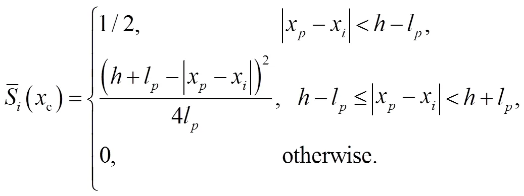
Note that the derivatives of the 1D GIMP shape functions are unchanged. As mentioned in the previous section, the multi-dimensional GIMP shape functions are constructed as tensor products of the 1D shape functions. Thus, derivatives of the 2D generalized interpolation functions at the centre of the element can be calculated as
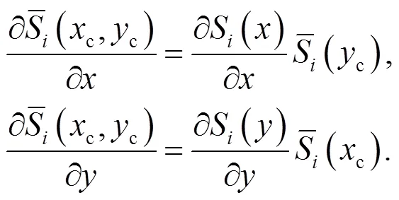

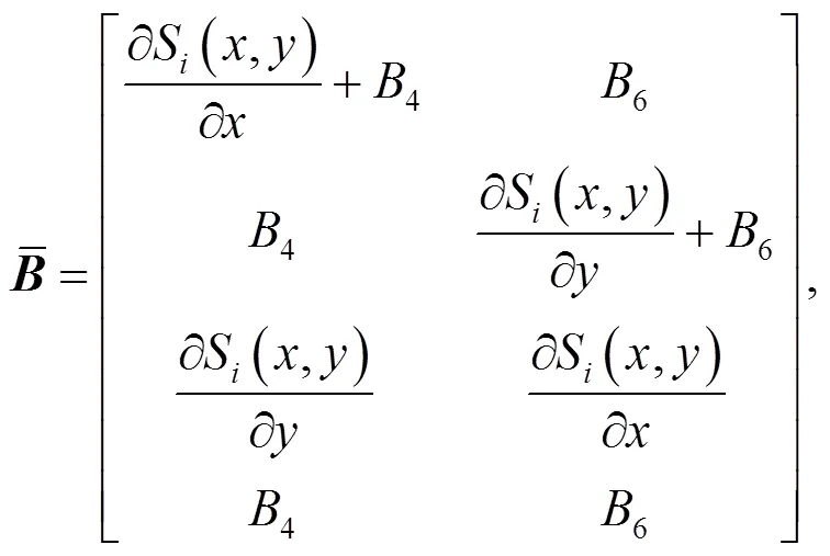
with
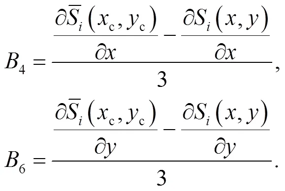
3 Numerical examples
In this section four numerical examples of increasing numerical complexity are presented: (a) 1D column compression, (b) slope failure in von Mises soil, (c) slope failure in Mohr-Coulomb soil, and (d) penetration of a rigid footing in Tresca soil. The performance of the proposed method in reducing cell cross error and volumetric locking was evaluated. In the first two examples, a thorough comparison of the results from the iMPM and iGIMP methods highlights the improvement of iGIMP in reducing the cell crossing error. In the last two examples, the improvement of iGIMP with B-bar in overcoming stress oscillations due to volumetric locking is demonstrated. For the purpose of the development of the proposed iGIMP with B-bar formulation, an in-house objected oriented MPM program was coded in C++.
3.1 One-dimensional column in compression
A 1D column in gravity compression as described by Bardenhagen and Kober (2004) was simulated here as a verification of iMPM and iGIMP implementations. The column has an initial height of=50 m and an initial width of=1.0 m. The following material parameters were used: Young’s modulus=1.0 MPa, Poisson’s ratio=0.0, and the unit weight=10 kN/m3. The self-weightof the column was increased from 0 to 10 kN/m3in a total of 10 load steps with linear load increments. The geometry and boundary conditions of the column are shown in Fig. 2. The column is divided into 50 four-node linear elements. To validate the proposed approach, the iMPM and iGIMP results were compared with the analytical solution (Bardenhagen and Kober, 2004; Zhang et al., 2011). The analytical solution of the stress and displacement can be written as (Zhang et al., 2011)

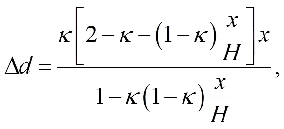
whereis the current coordinate of the column, and ∆is the displacement.
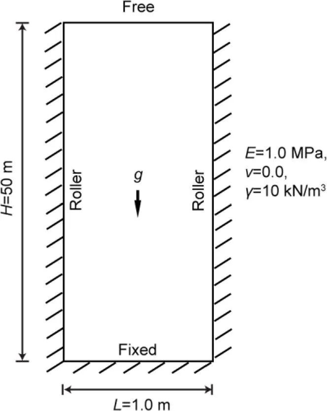
Fig. 2 Geometry and boundary conditions of the column
The initial positions of the material points did not have much influence on the accuracy of the result in MPM. The simplest way to initialize the locations of the material points is to use Gauss integration point positions. However, in this study the initial positions of the material points were evenly spaced over the domain instead of located at the Gauss integration point positions, as the gaps or overlaps in particle characteristic functions decrease the accuracy of the result in GIMP.
The vertical stress against the column height using iMPM and iGIMP with various particle densities at the final load step is shown in Fig. 3. A significant stress oscillation was found in the iMPM results, with four particles per cell. Increasing the number of particles (i.e. 25 particles per cell) only slightly decreased the stress oscillation. However, when GIMP was used, the stress oscillation greatly decreased, even with four particles per cell being used. Increasing the number of particles per cell to 25 greatly decreased the stress oscillation and improved the accuracy of iGIMP. Fig. 4 shows the vertical stress contour profile along the column at the final load step using iMPM and iGIMP. The iMPM results (Fig. 4a) showed significant numerical noise. As discussed in previous sections, the numerical noise of the stress profile is caused by cell crossing of the material points; the error of displacement in iMPM is caused by this numerical noise as well. In contrast, the stress results of iGIMP (Fig. 4b) showed a much smoother stress profile.
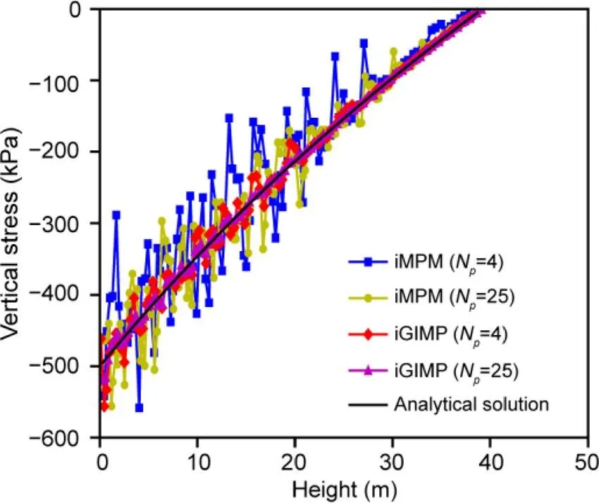
Fig. 3 Vertical stress plot along the column for iMPM, iGIMP, and analytical solutions
To quantitatively compare the performance of the various algorithms investigated in this paper, the tip displacement of the column was used as an accuracy check. The relative error of the tip displacement with various material point densities, is defined as
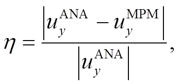
3.2 Slope stability in von Mises soil
In this section we describe the analysis of a slope stability problem using an elastic perfect-plastic soil model. A similar problem was studied by Beuth et al. (2011) using the iMPM. The soil of the slope was modelled using the von Mises failure criterion. To evaluate the performance of the proposed iGIMP with B-bar approach in simulating nearly-incompressible material, an undrained condition was assumed. The following material parameters were used: Young’s modulus=100 kPa, Poisson’s ratio=0.495, and cohesion=1.0 kPa. The selected material parameters were the same as those used by Beuth et al. (2011), except that a Poisson’s ratio=0.33 was adopted by Beuth et al. (2011). The slope has a height () of 1 m, a base length (2) of 2 m, and a slope angle () of 45° (Fig. 6). The following boundary conditions were assumed: the bottom of the mesh is fixed, whereas the left and right boundaries are fixed only in the horizontal direction, and the rest boundaries of the slope are free. The slope was loaded by increasing the unit weight of the soil to a value of=10 kN/m3. The background mesh was made up of 4-node linear square elements with a length of 0.05 m. The slope was discretized into 9760 and 15 250 material points when using initially 16 and 25 material points per element, respectively. The initial material point locations and background mesh of the slope are shown in Fig. 7.
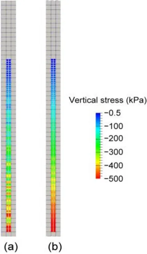
Fig. 4 Vertical stress of particles for iMPM (a) and iGIMP (b) analyses
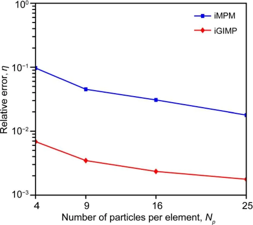
Fig. 5 Results of a convergence study for the iMPM and iGIMP analyses, for various particle densities
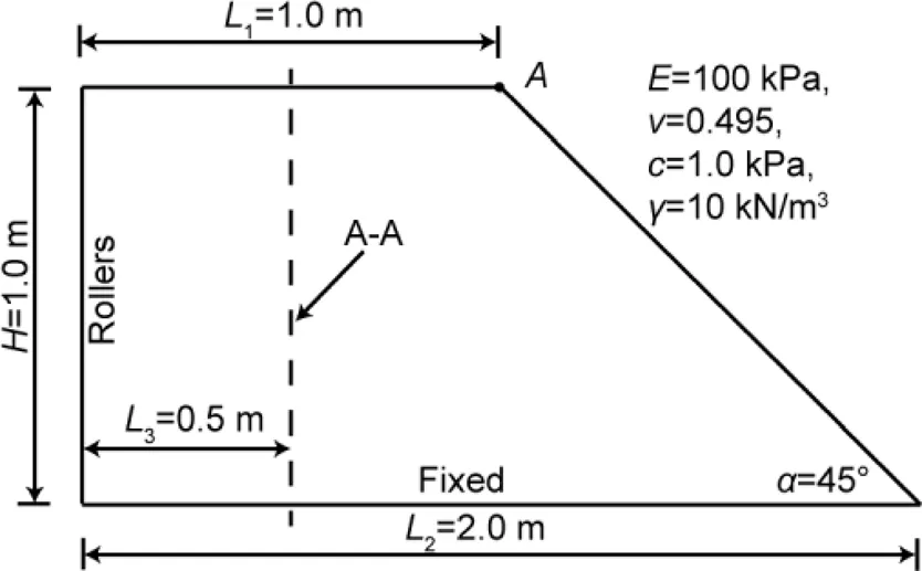
Fig. 6 Geometry and boundary conditions of the von Mises soil slope
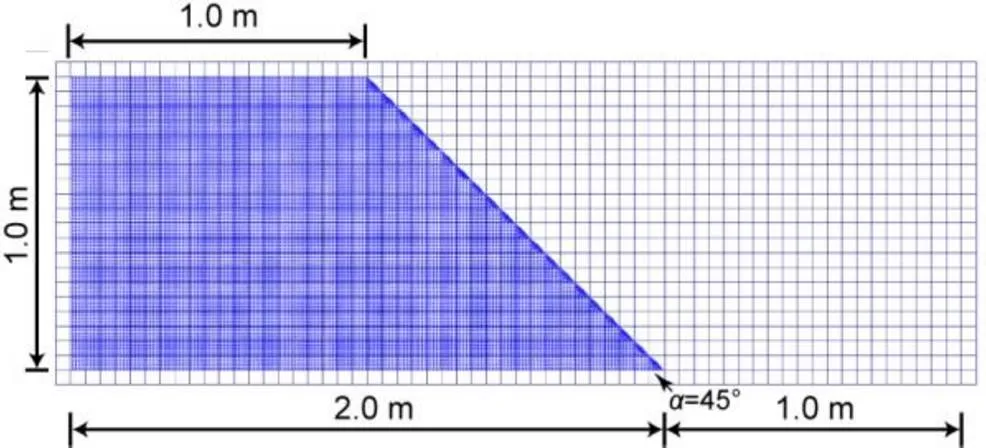
Fig. 7 Initial material points and background mesh
The soil unit weight as a function of the total displacement of the slope crest for both iMPM and iGIMP with 16 and 25 material points per element are presented in Fig. 8. Since the undrained condition was considered in this analysis, both the iMPM and iGIMP results were much “stiffer” than those with the B-bar approach, indicating that the volumetric locking issue was observed. Furthermore, it demonstrated that the GIMP method cannot overcome the volumetric locking issue, and an extra solution such as the B-bar approach is necessary for iGIMP. The vertical stress along the center of the background mesh column 0.5 m from the left (see cross-section A-A in Fig. 6) at a gravitational loading of= 10 kN/m3is plotted in Fig. 9. The iMPM simulation shows clear numerical noise in the stress plot. In contrast, the iGIMP results are much smoother and show much less numerical noise.
The vertical stress contours of the slope at the final load step for iGIMP, iGIMP with B-bar, and iMPM with B-bar with 25 particles per cell are shown in Fig. 10. Serious stress oscillations and a checkerboard pattern are observed for the iGIMP results due to the nearly incompressible constraints. On the other hand, excellent solution stability is observed for both the iMPM with B-bar and iGIMP with B-bar analyses. Moreover, due to volumetric locking, the displacements of the iGIMP were much smaller than those of the iGIMP with B-bar and iMPM with B-bar. This clearly demonstrates that volumetric locking was eliminated using the B-bar approach. Although small stress oscillations could be found for both the iMPM with B-bar and iGIMP with B-bar analyses, the iGIMP with B-bar results were much smoother than those of the iMPM with B-bar. Note that the average iterations per step with 16 particles per cell were 3.99 for iMPM and 5.58 for iGIMP. In general, the Newton iterative procedure showed a slower convergence rate for iGIMP analysis than for iMPM analysis. This is caused by the use of the non-physical modification of the gradient of shape function in iGIMP. Note that a quasi-static implicit formulation is not able to capture the whole dynamic failure process of landslides, and further extension to dynamic formulations is necessary in future work.
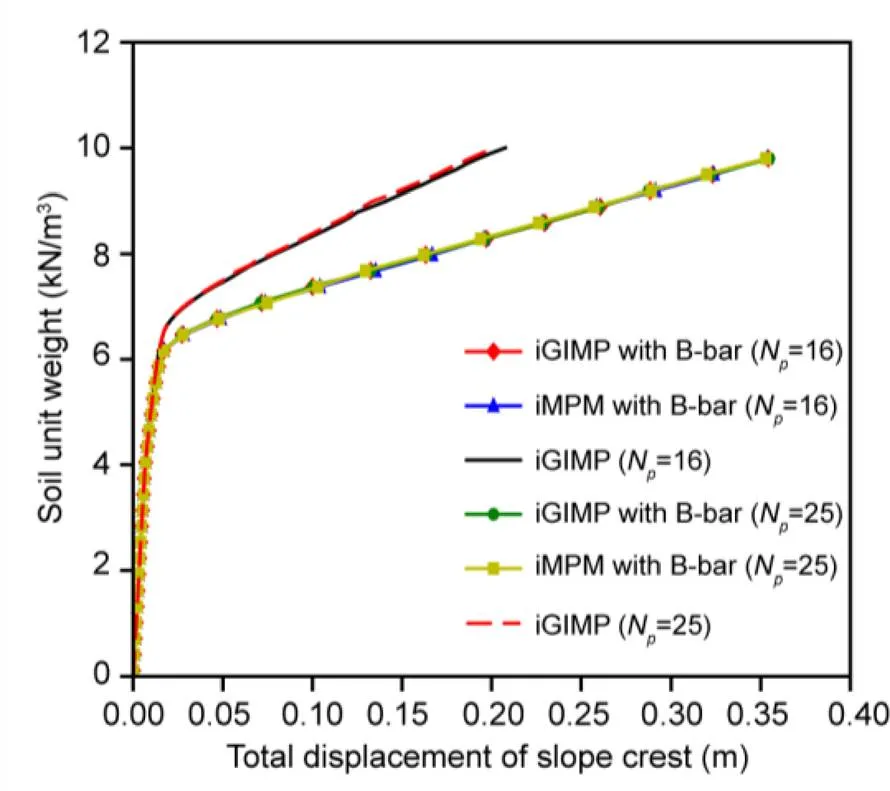
Fig. 8 Load-displacement curves for iMPM and iGIMP analyses for various particle densities
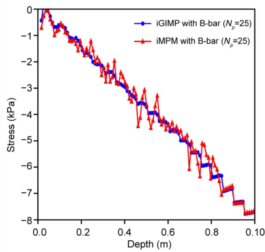
Fig. 9 Vertical stress along the cross-section A-A for iMPM and iGIMP analyses at a gravity loading of γ=10 kN/m3
3.3 Slope stability in Mohr-Coulomb soil

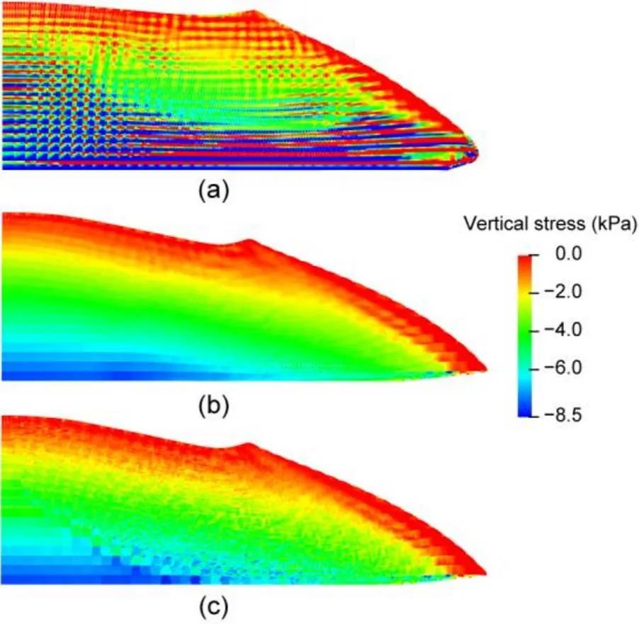
Fig. 10 Contours of vertical stress for iGIMP (a), iGIMP with B-bar (b), and iMPM with B-bar at a gravity loading of γ=10 kN/m3

Fig. 11 Geometry and boundary conditions of the Mohr-Coulomb soil slope
The same material parameters were used for the Mohr-Coulomb model as shown in (Smith et al., 2014): Young’s modulus,=100 MPa; Poisson’s ratio,=0.3; cohesion,=15 kPa; friction angle,=20°; unit weight,=20 kN/m3. Moreover, the dilation angle was=0°, thus, a non-associated rule was considered. The background mesh was made up of 23 254 four-node linear square elements with a length of 0.2 m. The slope was initially divided into 60 200 material points with four material points per element. The geometric configuration and the initial material point distribution of a homogeneous soil slope are given in Fig. 12.

Fig. 12 Initial material points and background mesh
The gravity loading was divided into 100 load steps, and no initial stress field was considered. A series of shear strength reduction factors (i.e. 1.0, 1.2, 1.4, 1.5, 1.55, 1.6, and 1.8) were simulated to obtain the FOS. The final maximum displacements of the slope versus strength reduction factors are given in Fig. 13. The maximum displacement increased rapidly at a strength reduction factor of 1.6, indicating an FOS of about 1.6. The calculated FOS is consistent with those obtained from the limit equilibrium method (LEM) (1.60) and FEM (1.59) (Smith et al., 2013). Furthermore, the maximum displacements of the slope for strength reduction factors (SRFs) smaller than 1.6 also agree well with those obtained using small strain FEM by Smith et al. (2013), which further verifies the proposed iGIMP with B-bar approach. The vertical stress distribution and the deformed material points obtained by iGIMP and iGIMP with B-bar at an SRF of 1.8 are given in Fig. 14. Again, strong oscillations were observed in the vertical stress field distribution simulated with the iGIMP method due to volumetric locking. The vertical stress field distributions show a typical checkerboard pattern (Fig. 14a). On the other hand, the checkerboard pattern caused by volumetric locking was mitigated by the iGIMP with B-bar approach (Fig. 14b).
3.4 Penetration of rigid footing in Tresca soil
The final numerical example given in this paper is that of rigid footing penetration into a weightless Tresca soil in the plane-strain condition. This benchmark example was considered by Sołowski and Sloan (2015) using an explicit GIMP approach, and the limit analysis solution based on rigid plastic is also available. Thus, it can be used as a benchmark to further validate the proposed iGIMP with B-bar approach in simulating large deformation problems.
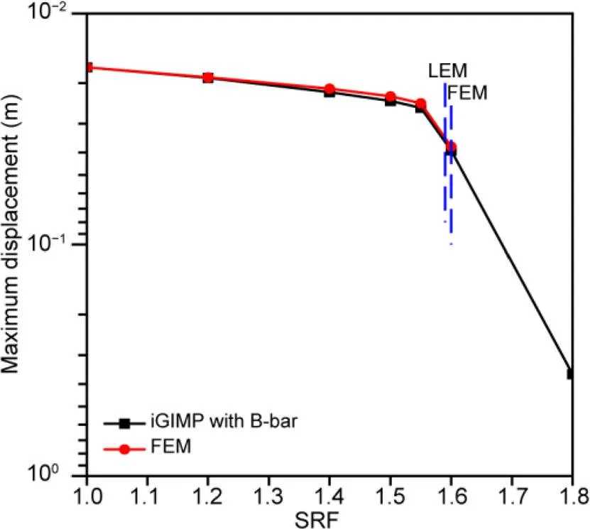
Fig. 13 Maximum displacement versus SRF from iGIMP with B-bar and FEM analyses
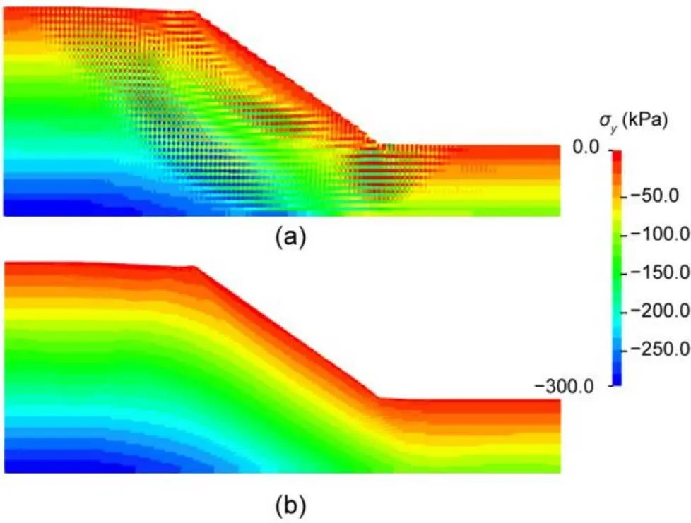
Fig. 14 Contours of vertical stress (σy) for iGIMP (a) and iGIMP with B-bar (b) with SRF=1.8
Due to symmetry, only half of the problem domain was considered and the footing had a half width of 1.0 m. The soil domain had a height of 5and a width of 5, whereis the width of footing. The bottom boundary was fixed in both vertical and horizontal directions, and the left and right boundaries were fixed only in the horizontal direction (Fig. 15). The background mesh had a height of 6and a width of 5, which is slightly larger than the soil domain to allow for deformations. A non-uniform initial distribution of material points was used (Fig. 16); the same setups were adopted by Sołowski and Sloan (2015) for their analysis of rigid footing (note that the material point density was not identical to that used by Sołowski and Sloan (2015)). A prescribed vertical displacement of 2 m was applied on the footing, with an incremental displacement of 0.001 m per step. The following Tresca material parameters were considered: undrained shear strength,u=1.0 kPa; Young’s modulus,=100 kPa; Poisson’s ratio,=0.495. The material parameters used were not identical to those used by Sołowski and Sloan (2015).
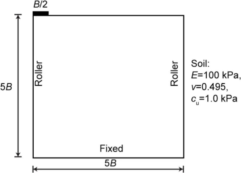
Fig. 15 Geometry and boundary conditions of the rigid footing problem
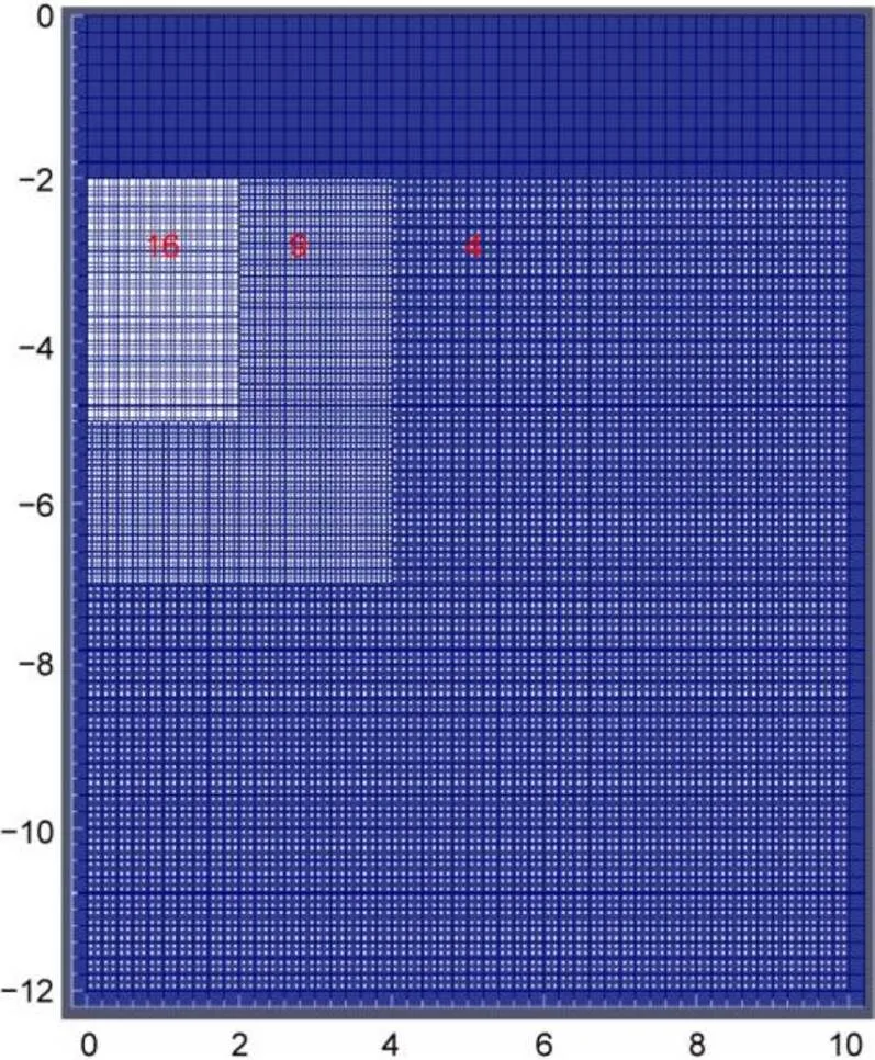
Fig. 16 Initial material points and background mesh with different initial material points per element
The normalized vertical resistance force (/u) versus penetration depth (/) curves obtained from the iGIMP with B-bar approach are shown in Fig. 17. This result was compared with that obtained from the limit analysis solution (Silva et al., 2011), and from numerical solutions such as particle finite element method (PFEM) (Yuan et al., 2021) (which was implemented in the commercial software Abaqus) and explicit GIMP (Sołowski and Sloan, 2015). In general, the result obtained by the proposed iGIMP with B-bar approach agrees well with the results of PFEM and explicit GIMP, whereas the standard iGIMP formulation provided a much stiffer response and failed to converge towards the reference results. To investigate the effect of mesh sensitivity, three simulations with different mesh and particle densities were considered. The results obtained by the iGIMP with B-bar approach (Fig. 17) converged towards the limit analysis solution of Silva et al. (2011) as the number of particles increased, which is consistent with the finding of Sołowski and Sloan (2015).
The profiles of incremental displacement magnitude, accumulated plastic strain invariant and the shear stresses are given in Fig. 18. The distributions of these fields obtained by the iGIMP with B-bar approach (the first row of Fig. 18) are consistent with those obtained by the Abaqus PFEM approach (the second row of Fig. 18) (Yuan et al., 2021). The vertical stress distributions at the end of the analysis for the standard iGIMP and iGIMP with B-bar approaches are given in Fig. 19. Similar to the previous example, the iGIMP solutions contained strong stress oscillations caused by nearly incompressible constraints, and a typical checkerboard pattern can be observed in most of the computational domain (Fig. 19a). The stress contour shown in Fig. 19b illustrates the correct compressive region underneath the footing, indicating that the checkerboard pattern caused by volumetric locking was mitigated by the iGIMP with B-bar approach.
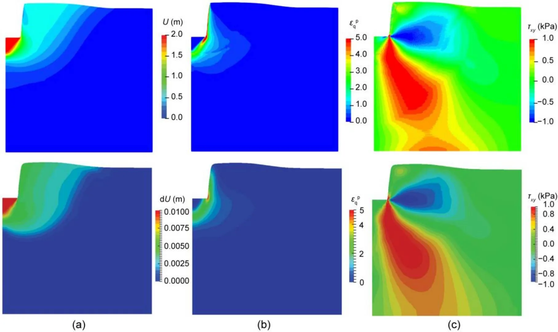
Fig. 18 Contour of displacements (U) (a), accumulated plastic strain invariant (εqp) (b), and shear stress (txy) (c) at a penetration depth of 1B obtained from iGIMP with B-bar (up) and PFEM (down) solutions. Reprinted from (Yuan et al., 2021), Copyright 2021, with permission from Springer Nature
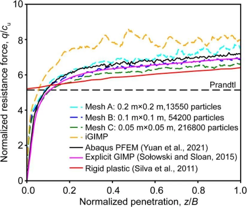
Fig. 17 Normalized resistance force versus penetration depth
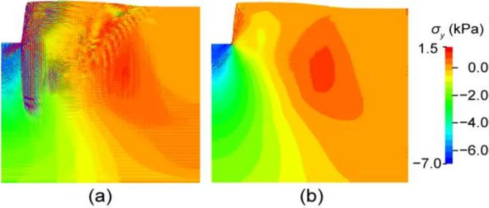
Fig. 19 Contours of vertical stress for iGIMP (a) and iGIMP with B-bar (b) at a penetration depth of 1B
4 Conclusions
A new iGIMP method framework with B-bar has been developed for large deformation geotechnical problems. The superiority of iGIMP with B-bar in terms of reducing the cell crossing error and overcoming volumetric locking was highlighted through four numerical examples. Detailed descriptions of the approach formulation and implementation procedures were provided. For the first time the B-bar method has been used to overcome volumetric locking in the GIMP method for near-incompressible large deformation geotechnical problems. It is straightforward to implement the B-bar method into existing iGIMP methods, without any extra restriction on the form of the constitutive model or additional linearization to the stiffness matrix.
The performance of the iGIMP approach was first demonstrated via a compression study of a 1D column compression problem, in which the results obtained from iMPM and FEM analyses were compared. The superiority of the iGIMP approach in reducing cell crossing error, and thereby improving computational accuracy was illustrated. Additionally, an elasto-plastic slope stability problem was considered, to further illustrate the performance of the iGIMP method in overcoming cell crossing error in a 2D case. Finally, the performance of the proposed iGIMP with B-bar approach in overcoming volumetric locking was examined using two numerical examples: a slope stability problem with shear strength reduction and a rigid footing penetration. The results demonstrated that the proposed iGIMP with B-bar approach can overcome volumetric locking due to incompressibility and reduce stress oscillations. All the results show that the proposed iGIMP with B-bar approach can handle these large deformation problems well in geotechnical engineering.
Contributors
Wei-hai YUAN: conceptualization, methodology, software, writing-original draft. Hao-cheng WANG: methodology, software, writing-review & editing. Kang LIU: methodology, writing-review & editing. Wei ZHANG: methodology, writing-review & editing. Ding WANG: writing-review & editing. Yuan WANG: writing-review & editing.
Conflict of interest
Wei-hai YUAN, Hao-cheng WANG, Kang LIU, Wei ZHANG, Ding WANG, and Yuan WANG declare that they have no conflict of interest.
Abe K, Soga K, Bandara S, 2014. Material point method for coupled hydromechanical problems., 140(3): 04013033. https://doi.org/10.1061/(ASCE)GT.1943-5606.0001011
Bandara S, Soga K, 2015. Coupling of soil deformation and pore fluid flow using material point method., 63:199-214. https://doi.org/10.1016/j.compgeo.2014.09.009
Bardenhagen SG, Kober EM, 2004. The generalized interpolation material point method., 5(6):477-495. https://doi.org/10.3970/CMES.2004.005.477
Bardenhagen SG, Brackbill JU, Sulsky D, 2000. The material-point method for granular materials., 187(3-4):529-541. https://doi.org/10.1016/S0045-7825(99)00338-2
Bathe KJ, 1996. Finite Element Procedures. Prentice Hall, Englewood Cliffs, USA.
Beuth L, Więckowski Z, Vermeer PA, 2011. Solution of quasi-static large-strain problems by the material point method., 35(13):1451-1465. https://doi.org/10.1002/nag.965
Charlton TJ, Coombs WM, Augarde CE, 2017. iGIMP: an implicit generalised interpolation material point method for large deformations., 190: 108-125. https://doi.org/10.1016/j.compstruc.2017.05.004
Coetzee CJ, 2004. The Modelling of Granular Flow Using the Particle-in-cell Method. PhD Thesis, University of Stellenbosch, Stellenbosch, South Africa.
Coetzee CJ, Vermeer PA, Basson AH, 2005. The modelling of anchors using the material point method., 29(9):879-895. https://doi.org/10.1002/nag.439
Coombs WM, Charlton TJ, Cortis M, et al., 2018. Overcoming volumetric locking in material point methods., 333:1-21. https://doi.org/10.1016/j.cma.2018.01.010
Cummins SJ, Brackbill JU, 2002. An implicit particle-in-cell method for granular materials., 180(2):506-548. https://doi.org/10.1006/jcph.2002.7101
Guilkey JE, Weiss JA, 2003. Implicit time integration for the material point method: quantitative and algorithmic comparisons with the finite element method., 57(9):1323-1338. https://doi.org/10.1002/nme.729
Guilkey JE, Hoying JB, Weiss JA, 2006. Computational modeling of multicellular constructs with the material point method., 39(11):2074-2086. https://doi.org/10.1016/j.jbiomech.2005.06.017
Huang P, Zhang X, Ma S, et al., 2011. Contact algorithms for the material point method in impact and penetration simulation., 85(4):498-517. https://doi.org/10.1002/nme.2981
Hughes TJR, 1980. Generalization of selective integration procedures to anisotropic and nonlinear media., 15(9):1413-1418. https://doi.org/10.1002/nme.1620150914
Iaconeta I, Larese A, Rossi R, et al., 2019. A stabilized mixed implicit material point method for non-linear incompressible solid mechanics., 63(6):1243-1260. https://doi.org/10.1007/s00466-018-1647-9
Jassim I, Stolle D, Vermeer P, 2013. Two-phase dynamic analysis by material point method., 37(15):2502-2522. https://doi.org/10.1002/nag.2146
Lemiale V, Nairn J, Hurmane A, 2010. Material point method simulation of equal channel angular pressing involving large plastic strain and contact through sharp corners., 70(1): 41-66. https://doi.org/10.3970/cmes.2010.070.041
Li F, Pan JZ, Sinka C, 2011. Modelling brittle impact failure of disc particles using material point method., 38(7):653-660. https://doi.org/10.1016/j.ijimpeng.2011.02.004
Li JG, Hamamoto Y, Liu Y, et al., 2014. Sloshing impact simulation with material point method and its experimental validations., 103:86-99. https://doi.org/10.1016/j.compfluid.2014.07.025
Mast CM, Mackenzie-Helnwein P, Arduino P, et al., 2012. Mitigating kinematic locking in the material point method., 231(16):5351-5373. https://doi.org/10.1016/j.jcp.2012.04.032
Mieremet MMJ, Stolle DF, Ceccato F, et al., 2016. Numerical stability for modelling of dynamic two-phase interaction., 40(9):1284-1294. https://doi.org/10.1002/nag.2483
Nair A, Roy S, 2012. Implicit time integration in the generalized interpolation material point method for finite deformation hyperelasticity., 19(6):465-473. https://doi.org/10.1080/15376494.2010.550082
Smith IM, Griffiths DV, Margetts L, 2014. Programming the Finite Element Method, 5thEdition. John Wiley & Sons, New York, USA.
Soga K, Alonso E, Yerro A, et al., 2016. Trends in large-deformation analysis of landslide mass movements with particular emphasis on the material point method., 66(3):248-273.https://doi.org/10.1680/jgeot.15.LM.005
Sołowski WT, Sloan SW, 2015. Evaluation of material point method for use in geotechnics., 39(7):685-701. https://doi.org/10.1002/nag.2321
Steffen M, Kirby RM, Berzins M, 2008. Analysis and reduction of quadrature errors in the material point method (MPM)., 76(6):922-948. https://doi.org/10.1002/nme.2360
Sulsky D, Kaul A, 2004. Implicit dynamics in the material-point method., 193(12-14):1137-1170. https://doi.org/10.1016/j.cma.2003.12.011
Sulsky D, Chen Z, Schreyer HL, 1994. A particle method for history-dependent materials., 118(1-2):179-196. https://doi.org/10.1016/0045-7825(94)90112-0
Sulsky D, Schreyer H, Peterson K, et al., 2007. Using the material-point method to model sea ice dynamics., 112(C2):C02S90.https://doi.org/10.1029/2005JC003329
Wang B, Hicks MA, Vardon PJ, 2016a. Slope failure analysis using the random material point method., 6(2):113-118. https://doi.org/10.1680/jgele.16.00019
Wang B, Vardon PJ, Hicks MA, 2016b. Investigation of retrogressive and progressive slope failure mechanisms using the material point method., 78:88-98. https://doi.org/10.1016/j.compgeo.2016.04.016
Wang B, Vardon PJ, Hicks MA, et al., 2016c. Development of an implicit material point method for geotechnical applications., 71:159-167. https://doi.org/10.1016/j.compgeo.2015.08.008
Wang B, Vardon PJ, Hicks MA, 2018. Rainfall-induced slope collapse with coupled material point method., 239:1-12. https://doi.org/10.1016/j.enggeo.2018.02.007
Wiȩckowski Z, 2004. The material point method in large strain engineering problems., 193(39-41):4417-4438. https://doi.org/10.1016/j.cma.2004.01.035
Yamaguchi Y, Takase S, Moriguchi S, et al., 2020. Solid–liquid coupled material point method for simulation of ground collapse with fluidization., 7(2):209-223. https://doi.org/10.1007/s40571-019-00249-w
Yerro A, Alonso EE, Pinyol NM, 2015. The material point method for unsaturated soils., 65(3):201-217. https://doi.org/10.1680/geot.14.P.163
Yuan WH, Wang B, Zhang W, et al., 2019. Development of an explicit smoothed particle finite element method for geotechnical applications., 106:42-51. https://doi.org/10.1016/j.compgeo.2018.10.010
Yuan WH, Liu K, Zhang W, et al., 2020. Dynamic modeling of large deformation slope failure using smoothed particle finite element method., 17(7):1591-1603. https://doi.org/10.1007/s10346-020-01375-w
Yuan WH, Wang HC, Zhang W, et al., 2021. Particle finite element method implementation for large deformation analysis using Abaqus., 16:2449-2462.https://doi.org/10.1007/s11440-020-01124-2
Zhang DZ, Ma X, Giguere PT, 2011. Material point method enhanced by modified gradient of shape function., 230(16):6379-6398. https://doi.org/10.1016/j.jcp.2011.04.032
Zhang W, Zhong ZH, Peng C, et al., 2021. GPU-accelerated smoothed particle finite element method for large deformation analysis in geomechanics., 129:103856.https://doi.org/10.1016/j.compgeo.2020.103856
Zhao EJ, Dong YK, Tang YZ, et al., 2021. Numerical investigation of hydrodynamic characteristics and local scour mechanism around submarine pipelines under joint effect of solitary waves and currents., 222:108553.https://doi.org/10.1016/j.oceaneng.2020.108553
Zheng XC, Pisanò F, Vardon PJ, et al., 2021. An explicit stabilised material point method for coupled hydromechanical problems in two-phase porous media., 135:104112. https://doi.org/10.1016/j.compgeo.2021.104112
https://doi.org/10.1631/jzus.A2100219
TU431
May 11, 2021;
June 20, 2021;
Oct. 25, 2021
*Project supported by the National Natural Science Foundation of China (Nos. 41807223 and 51908175), the Fundamental Research Funds for the Central Universities (No. B210202096), the Natural Science Foundation of Guangdong Province (No. 2018A030310346), and the Water Conservancy Science and Technology Innovation Project of Guangdong Province (No.2020-11), China
Wei ZHANG, https://orcid.org/0000-0002-3933-0109
© Zhejiang University Press 2021
杂志排行
Journal of Zhejiang University-Science A(Applied Physics & Engineering)的其它文章
- Large deformation analysis in geohazards and geotechnics
- Large deformation analysis of slope failure using material point method with cross-correlated random fields*
- Implementation of absorbing boundary conditions in dynamic simulation of the material point method*
- Meso-scale corrosion expansion cracking of ribbed reinforced concrete based on a 3D random aggregate model*
