Energy management strategy based on dynamic programming with durability extension for fuel cell hybrid tramway
2021-11-04ShiyongTaoWeirongChenRuiGanLuoyiLiGuoruiZhangYingHanQiLi
Shiyong Tao • Weirong Chen • Rui Gan • Luoyi Li • Guorui Zhang • Ying Han • Qi Li
Abstract This paper proposes an energy management strategy for a fuel cell (FC) hybrid power system based on dynamic programming and state machine strategy, which takes into account the durability of the FC and the hydrogen consumption of the system. The strategy first uses the principle of dynamic programming to solve the optimal power distribution between the FC and supercapacitor(SC), and then uses the optimization results of dynamic programming to update the threshold values in each state of the finite state machine to realize real-time management of the output power of the FC and SC. An FC/SC hybrid tramway simulation platform is established based on RTLAB real-time simulator. The compared results verify that the proposed EMS can improve the durability of the FC,increase its working time in the high-efficiency range,effectively reduce the hydrogen consumption,and keep the state of charge in an ideal range.
Keywords Hydrogen ∙Fuel cell ∙Supercapacitor ∙Energy management strategy ∙Tramway
1 Introduction
Recently, the fuel cell (FC) hybrid tramway, as a new energy technology,has been widely concerned and studied due to its non-catenary, comfortable riding, energy-saving and environmentally friendly nature [1, 2]. The tram with an FC hybrid power system uses FCs as the main power source, and the lithium battery or supercapacitor (SC) as the auxiliary energy to supply the power shortage and recover the braking energy. For this reason,hydrogenation stations are set up to ensure the hydrogen supply of FCs,which leads to gradual withdrawal of the line traction power supply system. Thereby it possesses great potential and high flexibility in urban transportation [3–5].
By controlling the power output of FCs and auxiliary power supply, the energy management strategy (EMS) for the hybrid system should ensure the tram driving and recover braking energy,reduce the fluctuation of FC output power, and improve equipment durability and operation economy, so as to optimize the working performance of power system[6,7].At present,many scholars have done a lot of research on the EMS of hybrid vehicles and accumulated a lot of achievements.Contrastively,in the field of rail transit, the research about the EMS of the FC/SC hybrid tram is in the early stage.
Erdinc et al. [8] proposed a load balancing EMS on the basis of fuzzy logic, which uses wavelet transform to divide the load power into two parts: high frequency and low frequency, and then controls the output of the hybrid power system by the fuzzy logic.Garcı´a et al.[9]proposed an EMS in terms of operating modes for FC/battery/ultracapacitor for an electric tramway. Li et al. [10] combined the EMS with state machine strategy (SMS) and realized droop control of the FC–SC hybrid tramway, which not only optimizes the hydrogen consumption of the system but also improves the system efficiency. In order to keep the state of charge(SOC)of the energy storage system near the rated value, the dynamic factor is introduced into the cascade and fuzzy logic-based control [11].
As a global optimal theory,dynamic programming(DP)is often used to design the EMSs with different optimal goals, and then they have been compared with real-time energy management algorithms to discuss their performances.Xu et al.[7]pointed out that the cost of the FC and lithium battery should be taken as the objective function to ensure the global optimization; in this case, the penalty factor of the SOC was introduced, and when the SOC exceeded the limit margin, the cost would increase immediately.Fares et al.[12]developed a DP technique for optimizing fuel cell hybrid vehicles. Ansarey et al. [13]used multi-dimensional DP to achieve optimal energy management in a dual-storage FC hybrid vehicle. Compared with DP,the maximum principle has a better control effect on hybrid electric vehicles [14].
In Refs. [10–14], all EMSs can realize the power distribution of each power source. However, only a few studies have involved the EMS for the FC–SC hybrid tramway. In addition, most of the EMSs in the abovementioned work ignored the fluctuation of the FC system and the impact of a large amount of regenerative braking energy on the energy storage system. Therefore, by considering the durability and economy of FCs, the author proposes an EMS combining the DP and SMS (DP-SMS).The proposed method can reduce fluctuation of the FC system and hydrogen consumption and maintain the SOC of SCs.
The FC–SC hybrid tramway has high design costs and a long construction period, and most studies adopt simulations or scaled-down experiments; therefore, the control strategy of the experimental verification needs to be improved[15–17].As a safe, fast, reliable and economical real-time verification technology,the hardware-in-the-loop simulation has been widely used in power electronics,electric vehicles, robots and automatic control, which can ensure the verification results of the proposed method[18,19]. In this paper, a DP-SMS-based EMS for a proton exchange membrane fuel cell (PEMFC)/SC hybrid tramway is proposed and the hybrid system model is built, the hardware-in-the-loop experimental platform is established by RT-LAB.
This paper is organized as follows. Section 2 is dedicated to the modeling of the FC–SC hybrid power system.Section 3 introduces the proposed EMS for the hybrid tramways. The EMS performance is verified in RT-LAB real-time simulator in Sect. 4. Finally, the main conclusions are presented in Sect. 5.
2 Modeling of FC–SC hybrid power system
The FC/SC hybrid tramway is mainly composed of an FC system, an SC system, a traction system and the corresponding controller,as shown in Fig. 1,where D1is the FC DC/DC control signal;D2is the SC DC/DC control signal;Vbusis the DC bus voltage;Ploadis the load demand power;Vfcand Ifcare the output voltage and current of the FC,respectively.
The FC is connected to the direct current (DC) bus through a unidirectional DC/DC as the main power source,and the SC is connected to the DC bus through a bidirectional DC/DC as the backup power source. The auxiliary system and the traction system are directly supplied by the DC bus [10].
According to the dynamics principle, the power Preqobtained by the traction system from the DC bus is calculated by [16]

where Paux1is the power of auxiliary system such as airconditioning and lighting, PFCand PSCare, respectively,the output power of the FC and SC,ηFC_DC/DCand ηSC_DC/DCare the efficiency of the unidirectional DC/DC converter and bidirectional DC/DC converter,respectively.
2.1 Modeling of the FC system
The FC system uses the HD6-type PEMFC with a rated power of 150 kW produced by Ballard, and the specific parameters are listed in Table 1. The experimental and simulated results of the FC polarization curves are shown in Fig. 2 [20, 21].
The FC system efficiency mainly includes the FC stack efficiency, FC electrical efficiency, and unidirectional DC/DC efficiency. Of them, the FC stack efficiency is related to the internal chemical characteristics, and the FC electrical efficiency correlates to the power consumption of the FC auxiliary system. The FC stack efficiency ηstackis calculated by [22, 23]
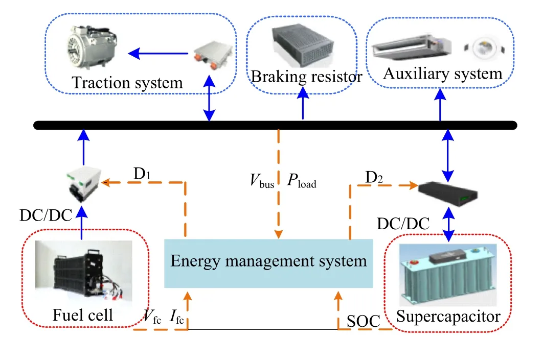
Fig. 1 Topology of the FC–SC hybrid power system
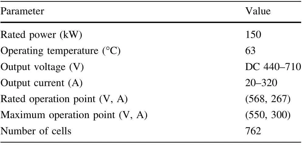
Table 1 Main parameters of the FC
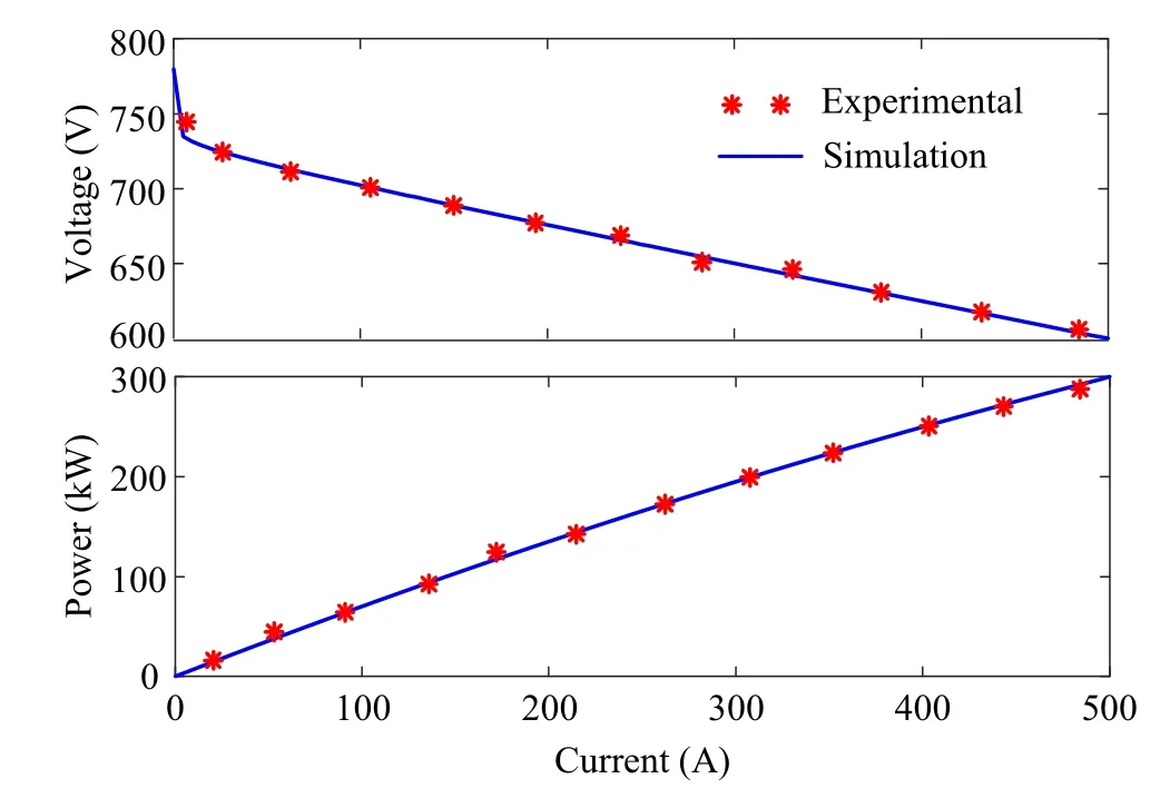
Fig. 2 Polarization curves of the FC
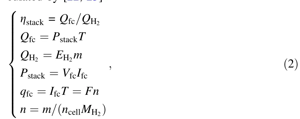
where QH2denotes the energy produced by the electrochemical reaction of hydrogen; Qfcis the output energy of FC stack; Pstackis the stack output power; T is the unit time;EH2is the higher heating value of hydrogen,which is 1.43 × 10⁵J/g; m is the mass of hydrogen consumed per unit time; Vfcand Ifcare the output voltage and output current of the FC, respectively; F is the Faraday constant,taking a value of 96,485 C/mol;n is the moles of hydrogen atoms; ncellis the number of stack cells; and MH2is the molar mass of hydrogen.
According to Eq. (2), the relationship between the FC stack efficiency and FC output voltage can be further inferred as
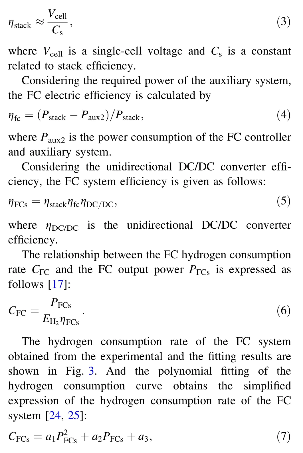
where a1, a2and a3are the polynomial fitting coefficients of FC hydrogen consumption.
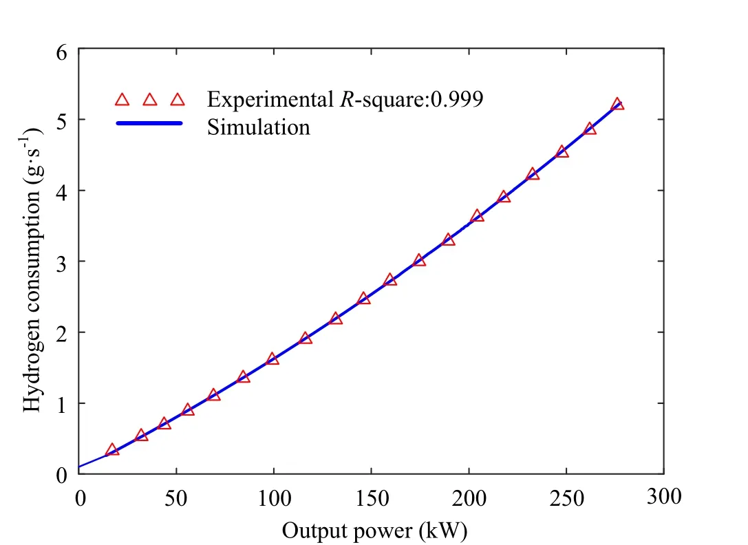
Fig. 3 Instantaneous hydrogen consumption curve of FC systems
2.2 Modeling of the SC system
The energy storage system of the hybrid power system is a series–parallel SC system produced by Maxwell company.The parameters are shown in Table. 2.
In order to obtain the charge and discharge internal resistance of the SC system, it is assumed that the performance of each SC module is equal, and the charge resistance is equal to the discharge resistance. The single SC system is charged with a 25 A intermittent current. The charging curve and calculation of internal resistance of a single SC are shown in Fig. 4.
Figure 4 shows the experimental data of a single SC. It is assumed that all SCs have the same performance.Table 2 shows the parameters of an SC module composed of 11 series and 6 parallel single SCs.
The internal resistance RSCis calculated according to the voltage and current during charging and the voltage when charging is stopped [26]:
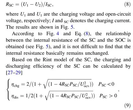
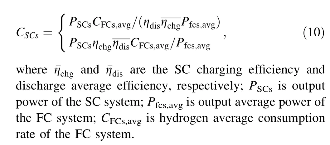
where ηchgand ηdisare the SC charging efficiency and discharge efficiency, respectively; RSCis the SC internal resistance; PSCis the SC output power;and Uocvis the SC open-circuit voltage.
Since the energy used to drive the tram is provided by the FC and SC, the internal consumption of the FC hybridpower system also comes from the FC and SC. In order to facilitate the analysis of the total hybrid power system during the operation of the FC tram hydrogen consumption,the charge and discharge energy of the supercapacitor is equivalent to the hydrogen consumption, that is, the instantaneous equivalent hydrogen consumption. The instantaneous equivalent hydrogen consumption rate of the SC system is calculated by the principle of equivalent hydrogen consumption:
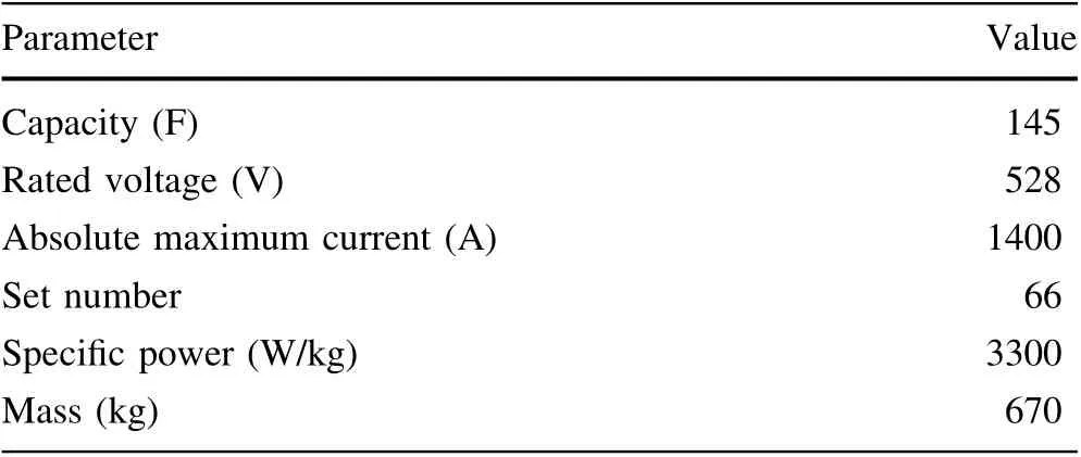
Table 2 Main parameters of the SC
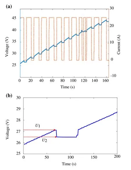
Fig.4 Test curves of a single SC:a charging curve and b calculation of internal resistance

Fig. 5 Internal resistance of a single SC
The relationship between the instantaneous equivalent hydrogen consumption of the SC,output power and SOC is shown in Fig. 6.
3 EMS for the hybrid tramways
To avoid the power shortage or excess of SCs,and improve the durability of the FC and fuel economy,considering the consistency of initial and final SOC state, we propose an EMS for the FC/SC hybrid tramways based on dynamic programming.
3.1 Principles of dynamic programming
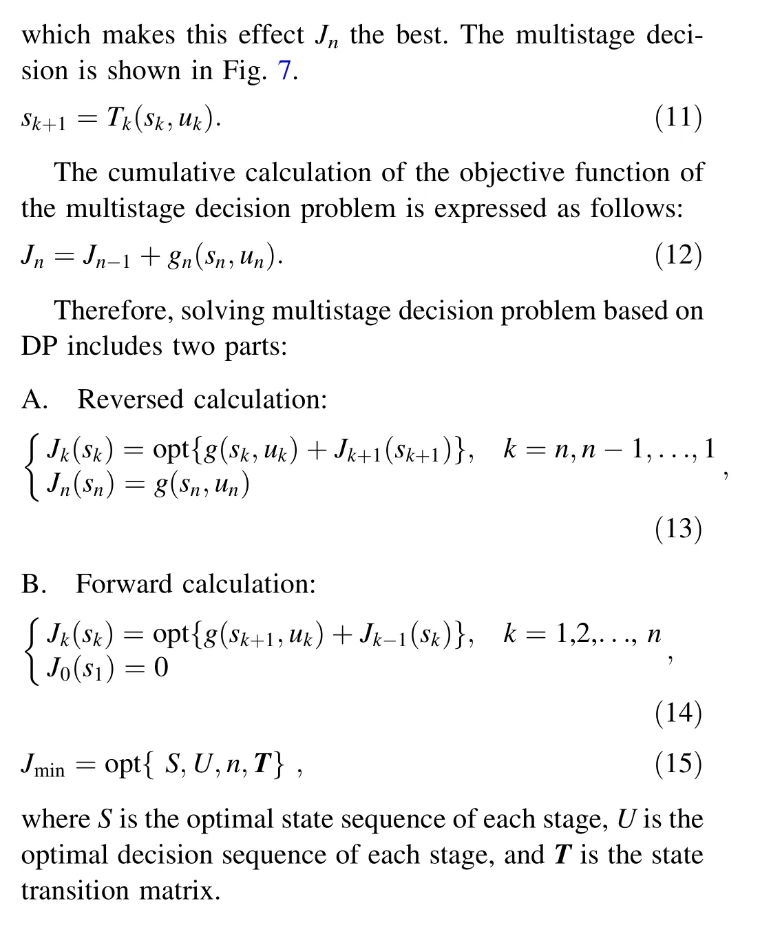
DP is a method to solve multistage decision problems,which can deal with nonlinearity and constraint problems well [12, 14]. The multistage decision process can be divided into several interrelated stages, the status of each stage is defined as s1,s2,…,sn,and the alternative decisions are u1, u2,…, un. In the kth stage (k ∊[1,n]), under the condition of decision uk, the changing relationship of the system state from skto sk+1is shown in Eq. (11),where Tkis the state transition matrix. The single-stage objective function is gk(sk,uk), and the multistage objective function is Jk(sk,uk).When the decision ukof each stage is selected,it constitutes a decision sequence called strategy U, which corresponds to a determined optimal effect Jn.Overall, the multistage decision problem is to find the strategy Uopt
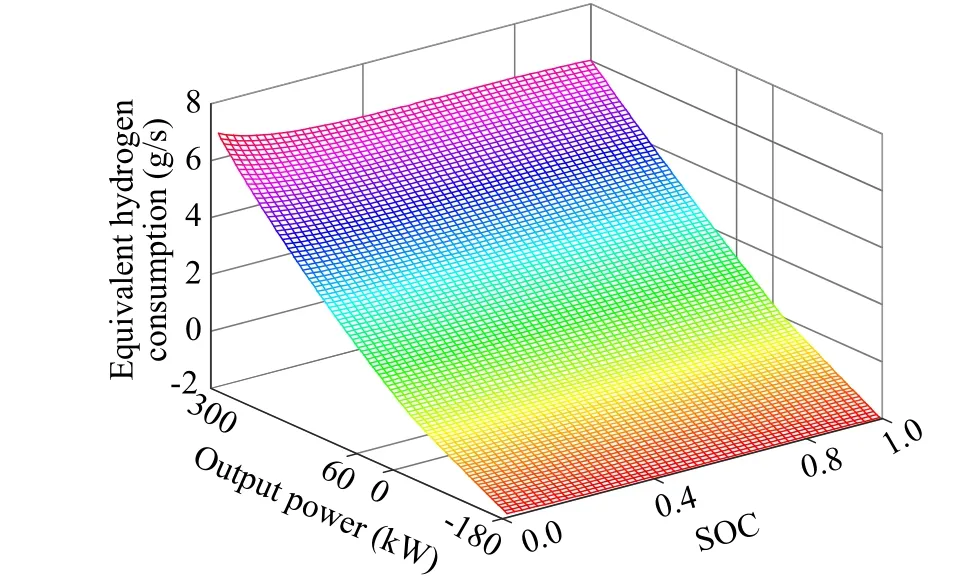
Fig. 6 Instantaneous hydrogen consumption of SCs
3.2 Discretization of state and decision
Discretize the operating conditions of the tram, the total operating time is n seconds, and the time interval is 1 s to obtain the total number of stages n of the FC/SC hybrid power system,and stage k is the k seconds of the operating conditions.
According to the FC/SC hybrid power system model,the SOC of the SC (SOC(k)) is selected as the state variable s(k)of the system,and the output power of the FC(PFC(k))is used as the decision variable u(k)of the system to realize the power distribution in different stages.
During the operation of the hybrid power system, the SOC needs to be maintained within a certain range to ensure that the SC runs in the best condition. Control the SOC threshold within 80%and 40%,and set the ideal point SOC to 70% in this work to improve the durability of the SC and obtain energy from regenerative braking. The constraints and discretization of SCs are as follows:
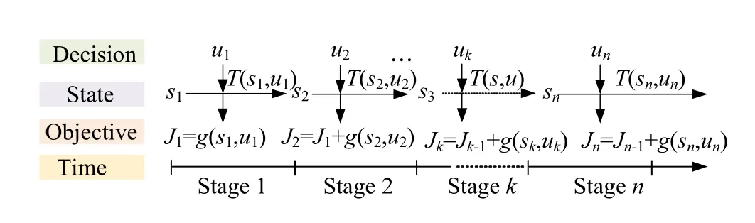
Fig. 7 Diagram of multistage decision
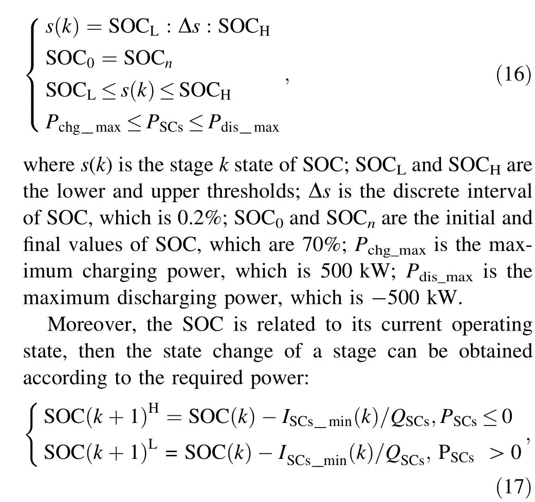
where SOC(k + 1)Hand SOC(k + 1)Lare the upper and lower limits of the next state SOC, respectively, which is determined by SOC(k); ISCs_min(k) is the minimum current of SC at stage k; QSCsis the real-time capacity of the SC system.
The output power of the FC as the decision quantity needs to be discretized to ensure the reasonable power allocation of the hybrid power system:
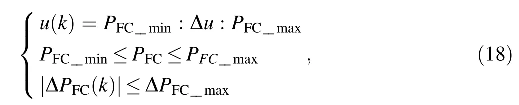
where PFC_min(20 kW) and PFC_max(270 kW) are the minimum power and maximum power outputs of the FC,respectively; Δu is the discrete interval of the single stage of the state variable PFC, which is 2 kW; ΔPFC_maxis the maximum output power change rate of the FC at stage k,which is 80 kW.
3.3 Objective function
The objective function reflects the performance of the system when the FC outputs different powers at stage k,and the range of the SC SOC(k + 1) that may reach the next state.
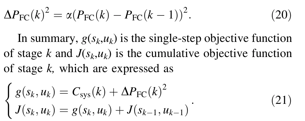
The hydrogen consumption of the FC–SC hybrid power system consists of the equivalent hydrogen consumption of the FC hydrogen consumption and the SC energy consumption.According to Eqs.(7)and(10),the instantaneous hydrogen at stage k of the FC hybrid power system is obtained as

where Csys(k) is the equivalent hydrogen consumption of the system at stage k;CFCs(k)is the hydrogen consumption of the FC at stage k; CSCs(k) is the equivalent hydrogen consumption of the SC at stage k.
In addition, the FC power change rate will be too high when accelerating and braking the tramway,which leads to the decline of FC service life [22]. Therefore, this work introduces the penalty coefficient α of the FC power change rate limit in the objective function:
3.4 Optimal power distribution
Optimal power distribution refers to the optimal output power distribution between FCs and SCs,and its purpose is to reduce the total hydrogen consumption of the hybrid power system and improve the durability of the fuel cell.
According to the analysis in Sects. 3.1 and 3.2,the basic idea of global optimization solution based on DP is shown in Fig. 8, where the time axis of the working condition is discretized into n stages, and the vertical axis is quantized as n different system states. The initial state and the end state of the SOC are constrained to be 70%. Further, the minimum cost function of all possible states at each stage and the optimal power output of FCs are determined by inverse calculation, and then the optimal output power sequence and the optimal system state sequence in the forward direction are generated according to the initial state of the system.
Figure 8 shows the DP reverse calculation process,where the terminal SOC state is SOCn,1; SOCk,jrepresents the jth reachable state at stage k;uk,j(PFC(k))represents the jth feasible decision at stage k, i.e., the FC output power;g(sk,uk,3) denotes the solution value when the decision is uk,3under skat stage k;J(sk,uk,3)represents the cumulative function value when the decision is uk,3under skat stage k. The specific steps of the reverse calculation are as follows:
Step 1 Calculate the value of the single-step cost function for all feasible states of SOCn,1transition to stage n-1.Step 2 Calculate the single-step cost function value in all states from stage n-1 to stage n-2. Take this step until the minimum value of Jn-2,jat stage n-2 is obtained,
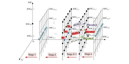
Fig. 8 Reverse calculation of DP
when Jn-2,jat the storage stage n-2 is matched with the corresponding state k and decision PFC(k).
Step 3 Repeat the operation of Step 2 for other stages until reaching SOC0,1; the initial state of the tramway satisfies SOC0,1= SOCn,1at stage 0, and the corresponding J0,1is the global minimum cost function value.Through reverse global optimization calculation, the effective SOC at each stage records the minimum cost function of the path and the corresponding SOC of the previous stage. Based on this, the forward optimization of DP can be performed to obtain the optimal power distribution of the FC hybrid power system.
Figure 9 shows the forward optimization calculation process of DP. The optimal decision sequence U in the entire working condition cycle is obtained based on that.The specific process of forward optimization is as follows:
(1) According to the inverse calculation results, the SOC state s1,j, FC output power u1,jand minimum objective function g(s1,j,u1,j) of stage 1 are obtained.
(2) Calculate the SOC state s2,j,FC output power u2,jand minimum objective function g(s2,j,u2,j) of stage 2 according to s1,jand u1,jobtained in (1).
Repeat the operation of Step (2) for other stages until reaching SOCn,1, the end state of tramway at stage n satisfies SOC0,1= SOCn,1, and the corresponding U is the global optimal strategy sequence set.
The optimal power distribution of the FC hybrid power system for tramways based on DP is shown as shown in Fig. 10.
Set the initial SOC0to 70% and the terminal SOCnto 70%. It can be seen from Eq. (21) that different penalty coefficients α will lead to different power distribution results. Therefore, this work calculates different penalty coefficients α with DP, and the results are shown in Figs. 11 and 12.
3.5 DP–SMS–based EMS
However, the power allocation results based on the DP solution are offline optimal, which cannot meet the needs of real-time management. Therefore, the SMS is introduced, and the offline optimal power allocation results are utilized to update the threshold value of each state in the state machine to realize real-time management of the output power of the FC and SC;i.e.,DP is used to optimize the threshold of the SMS.

Fig. 9 Forward calculation of DP
The traditional SMS divides the system into multilayer working modes according to the set standards, and each layer of working mode is divided into multiple sub-modes.The energy flow path for each sub-mode has its own characteristics, also known as the hierarchical control mode. In this work, the SOC is divided into three ranges:low SOC (<40%), medium SOC (40%–80%) and high SOC (>80%). The sub-modes in each SOC range set the threshold on the basis of DP,and then distribute the output power of FC and SC. The DP-SMS is shown in Fig. 13,where modes 1–10 fall into three states.
State 1: SOC of the supercapacitor is lower than 40%In this state,the energy storage of the SC is too low,and it should work in a charged state as much as possible.Meanwhile, the FC maintains a relatively stable output power to avoid insufficient power during periods of high power demand.
Mode 1:PFC_ref= PFC_optif Pbus+ PSC_chgmax≤PFC_opt,
Mode 2:PFC_ref= PFC_optif Pbus+ PSC_chgmax≤PFC_max,
Mode 3:PFC_ref= PFC_maxif Pbus+ PSC_chgmax>PFC_max,
where PFC_refis the reference value of FC output power;PFC_optis the optimal FC output power; Pbusis the power required by the load; PSC_chgmaxis the maximum SC charging power;PFC_maxis the maximum FC output power.

Fig. 10 Optimal power allocation based on DP
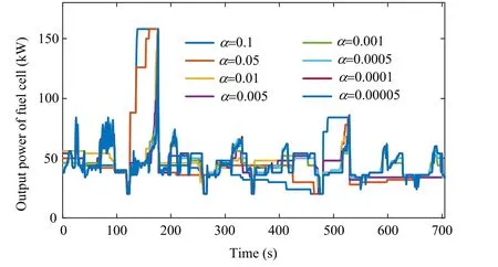
Fig.11 Power distribution of FC under different penalty coefficient α
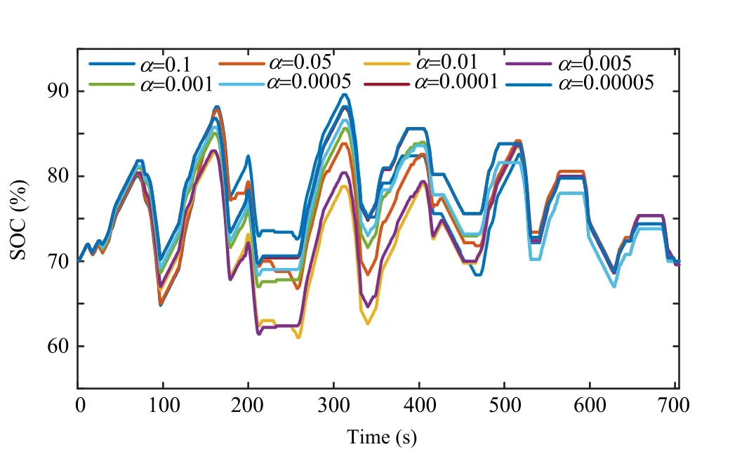
Fig. 12 SOC under different penalty coefficient α
State 2: SOC of the supercapacitor is constrained between 40 and 80%.
The SOC should be kept within this range,the FC should output the optimal power, and the power shortage is provided by the SC.
Mode 4: PFC_ref= PFC_minif Pbus+ PSC_chgopt-<PFC_opt,
Mode 5: PFC_ref= Pbusif Pbus≤PFC_opt,
Mode 6: PFC_ref= PFC_optif Pbus≤PFC_max,
Mode 7: PFC_ref= PFC_opt+ ΔPFCif Pbus>PFC_max,
where PFC_minis the minimum FC output power;ΔPFCis the rate of change of FC output power.
State 3: SOC of the supercapacitor is greater than 80%.
At this time, the SC has sufficient energy and the FC outputs the optimal power, thereby reducing the hydrogen consumption of the system; if the FC output power is insufficient, the output power of the SC will increase.
Mode 8: PFC_ref= PFC_minif Pbus<PFC_opt,
Mode 9: PFC_ref= PFC_optif Pbus≤PFC_max,
Mode 10: PFC_ref= PFC_optif Pbus>PFC_max.
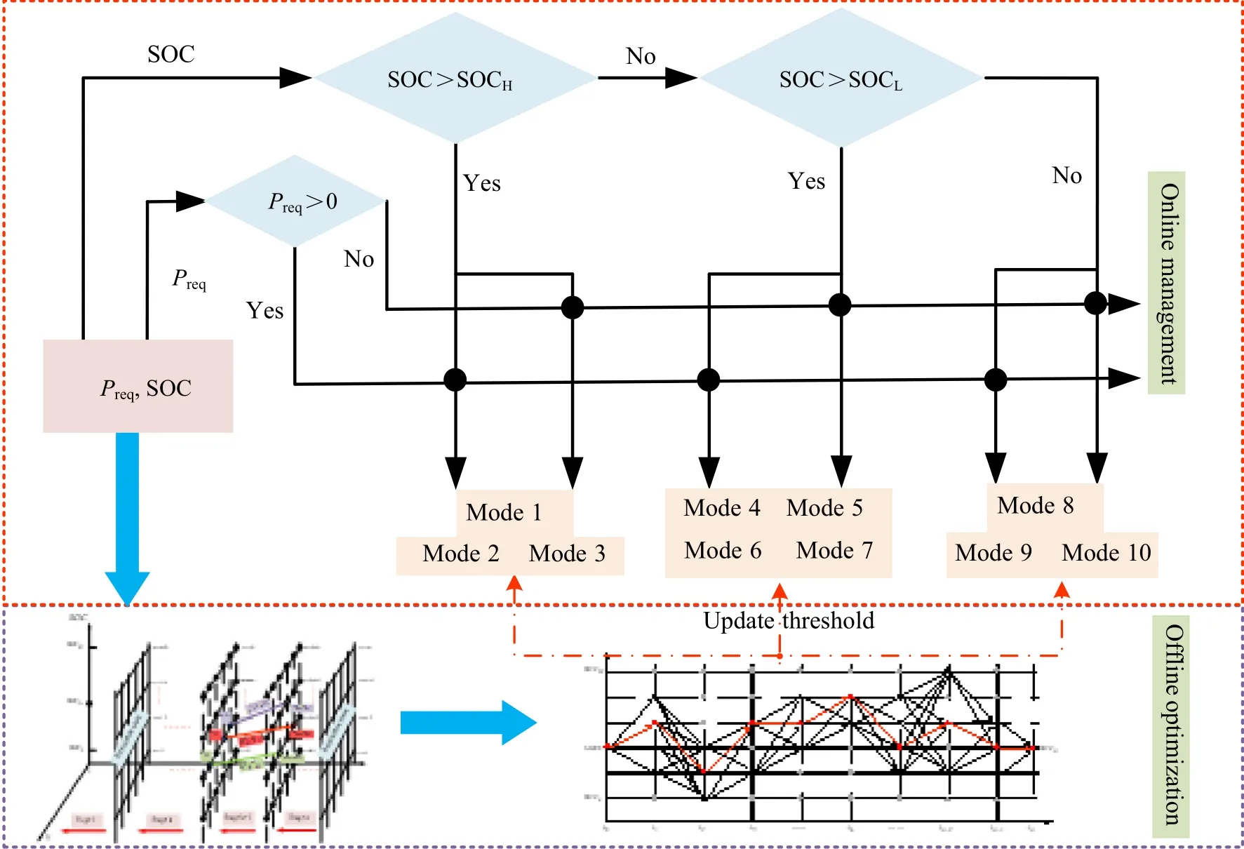
Fig. 13 Control chart of DP–SMS
4 Results and discussions
4.1 RT-LAB experimental platform
Based on the structural parameters of the FC–SC hybrid tramway, this work builds the experimental model of the hybrid system, including the FC system, SC system,DC/DC converter, traction inverter, traction motor, etc.,which is processed in real-time by the RT-LAB experimental system and transmitted to the RT-LAB target OP5600 through TCP/IP communication, as shown in Fig. 14. The EMS controller is connected with the RTLAB target computer for information exchange, and the whole operation process of the system is monitored by the host computer.
4.2 Verification and analysis
In order to verify the effectiveness and adaptability of the proposed EMS under different operating conditions, a semi-physical experimental platform is built, and the experiments are performed in actual operating conditions,and combined with DP-SMS-based EMS. The initial SOC value of the capacitor is 70%, and the target SOC value is 68% to 72%.
4.2.1 Tram operating case 1
Figure 15 shows the demand power curve of the tram in actual operating condition 1. It consists of several symmetrical round-trip paths and lasts 705 s. The required maximum power is about 750 kW, and the minimum is about 380 kW. The experimental results of the proposed EMS are shown in Figs. 16–22.
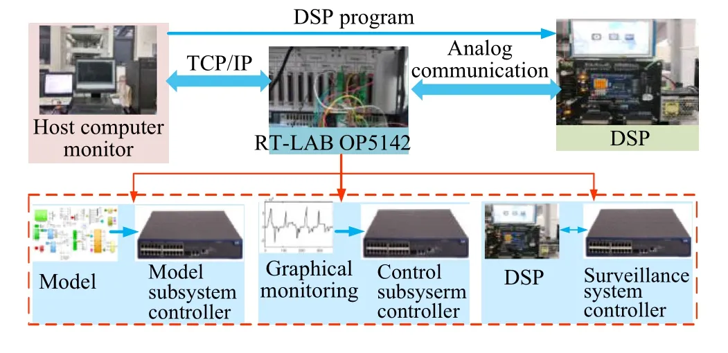
Fig. 14 Structure of RT-LAB experimental platform

Fig. 15 Operating condition of tramway for case 1
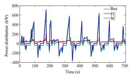
Fig. 16 Power distribution based on DP for case 1
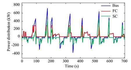
Fig. 17 Power distribution based on SMS for case 1
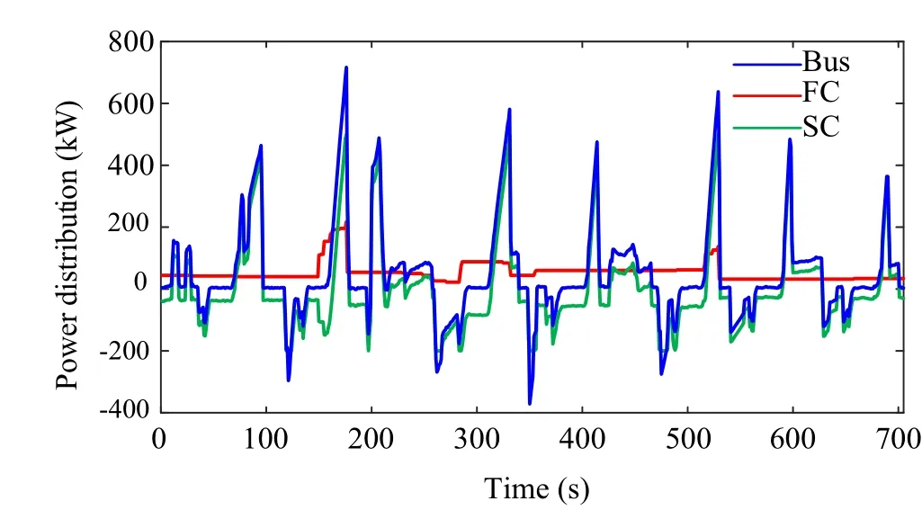
Fig. 18 Power distribution based on DP-SMS for case 1

Fig. 19 Output power of the FC for case 1
Figures 16, 17 and 18 show the results of power distribution under the three methods. In the traction stage, the FC is used as the main power, and the SC is used as the backup power; they supply the DC bus and then drive the tramway. While in the braking stage, the SC recovers the braking energy, and the FC outputs power to ensure the normal operation of the auxiliary system. At this time,because the discharge and charging current of the SC are affected by the bidirectional DC/DC, part of the braking recovery power is consumed by the braking resistor;therefore,all three methods can meet the power demand of the hybrid tramway.
The output power of the FC is compared under the three methods, revealing that the DP-based EMS fluctuates less;the SMS-based EMS tends to supply the tramway by the FC but the power fluctuates greatly,while the output power is the smoothest and has the least fluctuation.
When the operating conditions of the trams change, the FC hybrid power system changes the frequency of the FC output power to meet the system requirements.The smaller frequency is conducive to prolonging the service life of the power source. In order to analyze the impact of different EMSs on FC operating pressure, the Haar wavelet transform is used to decompose the FC output power into highfrequency and low-frequency parts.The standard deviation σ of the high-frequency part can well indicate the frequency of the power supply use. Figure 21 shows the results of the FC operating pressure analysis under DPSMS, DP and SMS. It is shown in Fig. 21 that the FC output power fluctuates the least under the DP-SMS with σ = 5.2738, which improves the durability of the FC and prolongs its service life.
In addition to focusing on the operation of the FC, this work compares the SOC of the SC as well. It can be seen from Fig. 22 that the SMS-based EMS can keep the SOC within the safe range, but the constraint force of SOC is weaker; the DP-based EMS can achieve initial and final SOC consistency,which means a stronger constraint force;the constraint force of DP-SMS-based EMS is in the middle, and the control effect is good.
Finally, this work compares the hydrogen consumption to verify the economy of the tramway system, as shown in Fig. 23. The results show that the DP-SMS hydrogenconsumption is lower than that of SMS-based EMS and are very similar to that of DP-based EMS.

Fig. 20 Distribution of FC operation power for case 1
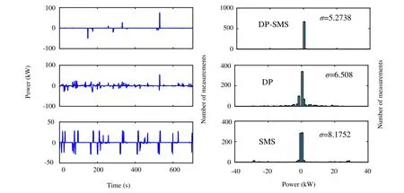
Fig. 21 Fluctuation of FC output power for case 1
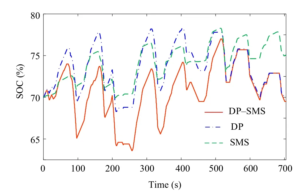
Fig. 22 Comparison of SOC for case 1
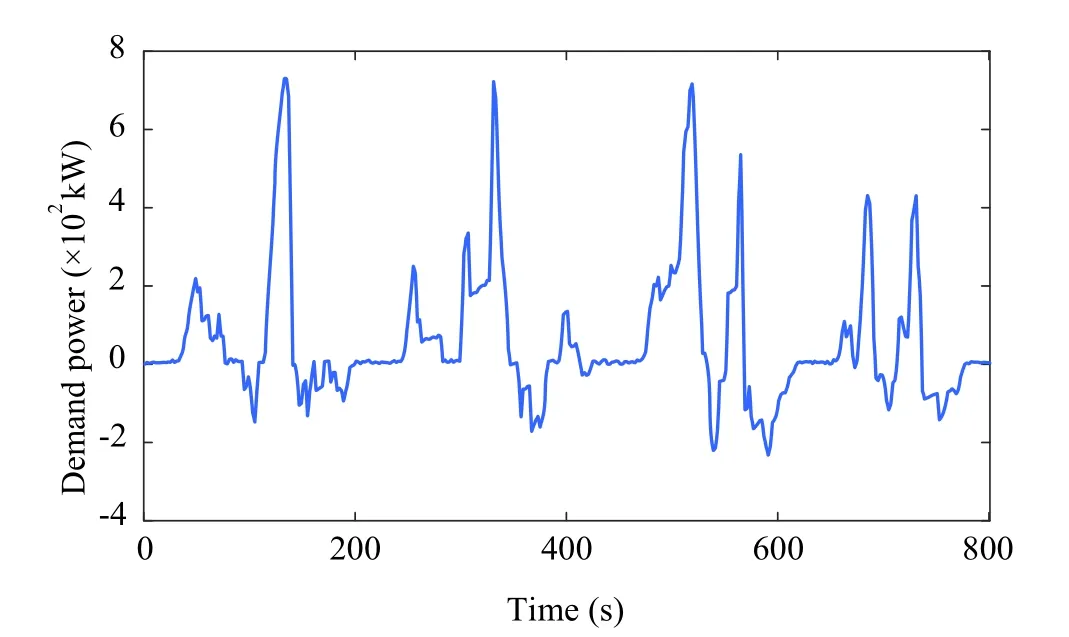
Fig. 23 Operating condition of tramway for case 2
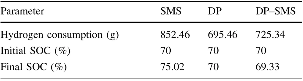
Table 3 Comparison of hydrogen consumption for case 1
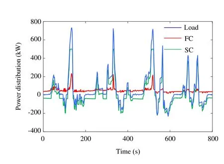
Fig. 24 Power distribution based on DP for case 2
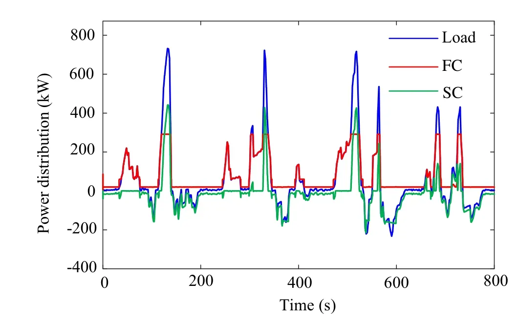
Fig. 25 Power distribution based on SMS for case 2
Table 3 summarizes the results of the comparison. The hydrogen consumption of DP-SMS-based EMS is reduced by 14.91%compared with SMS-based EMS,as well as the control effect of the SOC. Therefore, the DP-SMS-based EMS of the FC–SC hybrid system proposed has obvious advantages in hydrogen consumption and SOC maintenance.

Fig. 26 Power distribution based on DP-SMS for case 2
4.2.2 Tram operating case 2
Figure 23 shows the demand power curve of the tram in actual operating condition 2. It consists of several symmetrical round-trip paths and lasts 800 s. The required maximum power is about 780 kW and the minimum is about 240 kW. The experimental results of the proposed EMS are shown in Figs. 24–29.
The experiment results of case 2 are shown in Figs.24–30. The hydrogen consumption, SOC changes, and the FC system performance with deferent control methods are presented in Table 4. It can be seen from the above results that the method still has good performance under different tram operating conditions, which proves that the method still has superior robustness under uncertain operating conditions.
From the above analysis,it can be seen that based on the DP and SMS,the FC–SC hybrid optimal power distribution method can reasonably allocate the output power of the main and auxiliary power sources to ensure the normal running of the tram.Compared with the SMS,the proposed method can better control the SOC of the lithium battery system, improve the durability of the FC system, and reduce the hydrogen consumption; compared to DP, it improves the durability of the FC system and realizes realtime management of the output power of FCs and SCs.

Fig. 27 Output power of the FC for case 2
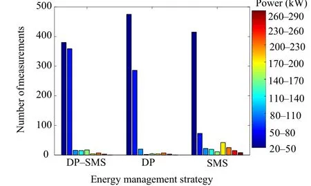
Fig. 28 Distribution of FC operation power for case 2
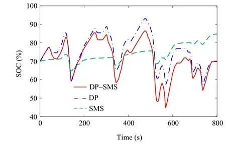
Fig. 30 Comparison of SOC for case 2
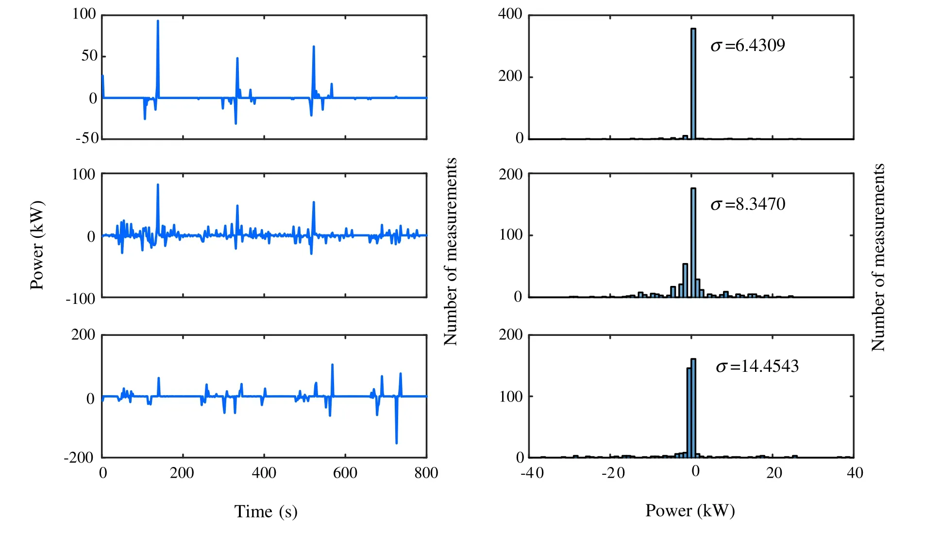
Fig. 29 Fluctuation of FC output power for case 2
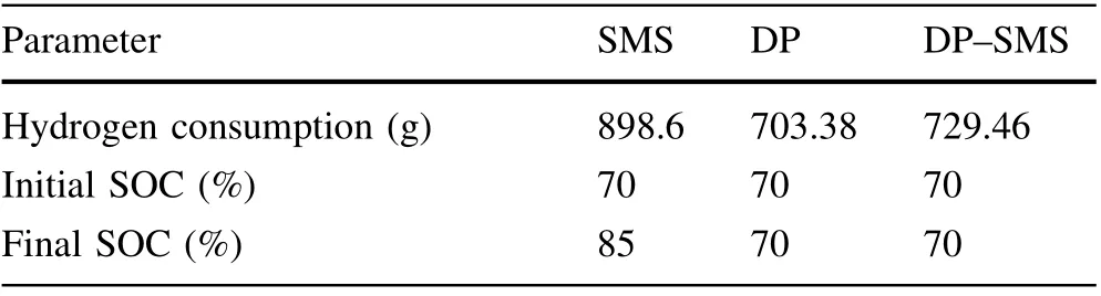
Table 4 Comparison of hydrogen consumption for case 2
5 Conclusions
A new EMS is developed for an FC–SC hybrid power,which equalizes the energy consumed by the SC to hydrogen, considers the durability of FC, optimizes the overall fuel of the system, reduces the fluctuation of the FC,and makes the FC operate more in high-efficiency part.It uses DP to optimize the setting threshold of the SMS and is able to make up for the disadvantages of DP: not suited to real-time control and slow calculation time. In order to verify the effectiveness and stability of the proposed method, the tram is operated under a real-time simulation platform built by RT-LAB with two different operating conditions. Compared with that of the SMS-based EMS,the hydrogen consumption of the DP-SMS is reduced by 14.91% in case 1 and 18.82% in case 2, while the fluctuation of FC output power is smaller than that in the DPbased EMS. In general, the proposed EMS significantly improves hydrogen consumption and moreover improves the durability of the FC system,and ensures that the SOC is in an ideal range.
AcknowledgementsThe authors would like to thank the reviewers for their helpful suggestions. This work was supported by the National Natural Science Foundation(Nos.51977181,52077180,and 52007157) and Fok Ying-Tong Education Foundation of China(No.171104).
Open AccessThis article is licensed under a Creative Commons Attribution 4.0 International License, which permits use, sharing,adaptation,distribution and reproduction in any medium or format,as long as you give appropriate credit to the original author(s) and the source,provide a link to the Creative Commons licence,and indicate if changes were made.The images or other third party material in this article are included in the article’s Creative Commons licence,unless indicated otherwise in a credit line to the material. If material is not included in the article’s Creative Commons licence and your intended use is not permitted by statutory regulation or exceeds the permitted use, you will need to obtain permission directly from the copyright holder. To view a copy of this licence, visit http://creativecommons.org/licenses/by/4.0/.
杂志排行
Railway Engineering Science的其它文章
- Preface to special issue on hybrid and hydrogen technologies for railway operations
- A review of hydrogen technologies and engineering solutions for railway vehicle design and operations
- An investigation into intermittent electrification strategies and an analysis of resulting CO2 emissions using a high-fidelity train model
- Analysis of positioning of wayside charging stations for hybrid locomotive consists in heavy haul train operations
- Feasibility study of a diesel-powered hybrid DMU
- Feasibility of hydrogen fuel cell technology for railway intercity services: a case study for the Piedmont in North Carolina