Design and research of magnetically levitated testbed with composite superconductor bearing for micro thrust measurement
2021-10-31FawziDERKAOUIZhaoxinLIU刘朝鑫WenjiangYANG杨文将YuQIN秦瑀KunlongWU吴坤隆PengZHAO赵鹏JuzhuangYAN闫炬壮JunxueREN任军学andHaibinTANG汤海滨
Fawzi DERKAOUI, Zhaoxin LIU (刘朝鑫), Wenjiang YANG (杨文将),Yu QIN (秦瑀), Kunlong WU (吴坤隆), Peng ZHAO (赵鹏), Juzhuang YAN(闫炬壮), Junxue REN (任军学) and Haibin TANG (汤海滨)
1 School of Astronautics, Beihang University, Beijing 100191, People’s Republic of China
2 School of Power Engineering,Liuzhou Railway Vocational Technical College,Liuzhou 545616,People’s Republic of China
3 School of Space and Environment, Beihang University, Beijing 100191, People’s Republic of China
Abstract A high temperature superconducting (HTS) magnetically levitated testbed has been developed for the steady thrust measurement of miniature ion electrospray thruster.The structure of the testbed mainly consists of an HTS composite bearing, a magnetic shielding plate, an active electromagnetic brake and a laser displacement sensor.The steady thrust is described as a function of the equilibrium angle displacement of the floating frame.Furthermore, the mechanical behaviors of HTS composite bearing were studied via finite element simulation and experiments, which include the load capacity, levitation stiffness and background noise.The results show that the thrust testbed can keep in low noise and have a load capacity up to 4 kg.According to the ignition testing of the electrospray thruster, the thrust force of 25.2μN was measured by the testbed,which is close to the design value of miniature ion electrospray thruster.
Keywords: micro-force measurement, maglev testbed, composite HTS bearing
1.Introduction
With the rapid development of micro-thrusters, more potential space applications such as micro-satellites formations are activated.Among them, the task of gravitational wave detection requires micro-thrusters to compensate for the space interference force by providing a very precise thrust,so the thrust performance has to be evaluated very accurately to prove the design of the precise micro-thrusters[1–3].In the past time,a lot of researches on micro-thrust measurement have been carried out and have made great progress.Up to now, the thrust in the sub-micro newton range can be measured by the mechanical pivot stand[4].
Hathaway from Canada designed a sensitive vacuum microthrust test stand,which introduced a pair of jewel-pivot bearings to measure the thrust of 1–100μN and the resolution is 20 nN.This type of pivot bearing can sustain significant load with extremely low rotation friction[4].Chakrabortyet alhas designed a thrust test stand which can measure the thrust up to 100μN,and the resolution is 10 nN.The device used the homodyne thrust measurement technique to effectively isolate the interference of facility vibration on thrust reading,and can be used for different types of micro thrusters [5].Soni and Roy form university of Florida designed a nano-Newton resolution thrust stand [6], and the logarithmic decrement method was proposed to calibrate the test stand.The uncertainty of calibration process can be limited to 5%by reducing the number of error sources.The signal analysis technology was used to analyze the noise source and its corresponding frequency band, and the noise correction sensor was introduced to further improve the resolution of the test stand.However, there are also some problems such as inability to effectively isolate noise, internal force interference and low load capacity in the mechanical pivot.To solve these problems, a micro-thrust testbed based on magnetic levitation with high temperature superconducting(HTS)composite bearings is shown in this paper.
The phenomenon of HTS magnetic levitation was first discovered in 1987.Nowadays,HTS magnetic bearing is one of the most prospective applications of bulk superconductors in stable levitation with considerable stiffness and self-stability due to its unique flux pinning property.HTS magnetic bearing has great potential application of emerging technologies such as magnetic levitation transportation [7] and flywheel energy storage systems (FESS) [8–11].Boeing has developed an HTS FESS with a speed of up to 22500 rpm and 5 kWh, which uses an axial magnetic bearing structure.The radial bearing structures were developed by Germany’s Nexans Superconducting Company and Siemens [12].Furthermore, the German ATZ company studied the levitation and stiffness characteristics of HTS bearings [13, 14].
To improve the levitation characteristics of micro-thrust testbed, an axial-radial composite HTS bearing was introduced in this paper, which can realize the self-stabilizing levitation of testbed without complex external control system and rotation loss influence.
2.Measuring principle and thruster
The measurement principle of the testbed based on the composite HTS bearing is similar to that of the traditional mechanical pivot stand.The thrust is calculated by the measured displacement or deformation of the floating frame.The oscillation of floating frame follows second-order equation:

where,θis the rotation angle,Iis the floating frame’s inertia moment,cis the damping coefficient of frame,kthe is restoring moment coefficient,RTthe is equivalent thrust arm length andFTis the thrust force.The schematic diagram of the thrust measurement is shown in figure 1.
According to vibration mechanics, if ignition frequency of the thruster is largely smaller than the natural frequency of floating frame, then the formula (1) can be simplified as:

This means that the thrust to be measured is mainly calculated from the restoring moment coefficientkand the amount of change in angle.The floating frame deviates from initial position under the action of thrust until the restoring force of the floating frame is equal to the small thrust and the frame oscillates near the new equilibrium point.The restoring moment coefficientkin formula(2)can be obtained through calibration,or obtained from the free oscillation curve of floating frame.The natural angular frequencyω0of the floating frame satisfies:

According to formula(3),the natural periodTof the floating frame can be obtained as:
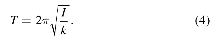
The restoring moment coefficientkis thus obtained as:

The rotation angle of floating frame can be obtained by the laser displacement sensor.The natural period is calculated according to the oscillation curve of floating frame.Finally, the thrust force can be calculated according to the formulas (2)–(5).
In this micro-thrust measurement, the miniature ion electrospray thruster developed by Beihang University is evaluated.The effective emission current reach 200μA and the thrust is about 20μN under the accelerating voltage of 2500 V.The thruster is shown in figure 2.
3.Design of thrust testbed
The structure of HTS magnetically levitated testbed is shown in figure 3.The whole propulsion system, including thrusters and power units,is installed on the floating frame to avoid the interference between power units and the HTS composite bearing to suppress noise of the testbed, which is an improvement on the previous version [15].The thruster is ignited when the floating frame is in stable levitation,and the rotation movement of floating frame is measured and analyzed to calculate the thrust.
3.1.Testbed structure
The challenge of using the deflection angle of the floating platform to calculate the thrust is to reduce the hysteresis in the floating frame.The sources of hysteresis mainly include restoring moments and different resistances such as rotational friction.Feasible measures to reduce hysteresis include the more reasonable structure design, precise counterweight and the horizontal adjustment of floating frame [16].
The restoring moment is mainly composed of gravity restoring moment and electromagnetic torque.The error caused by the fabrication and installation makes the floating frame have an inherent gravitational potential well.The nonuniform distribution of surrounding magnetic field produces an electromagnetic torque.The restoring moment coefficientkdetermined by the inherent restoring moment can be calculated by the passive calibration method.
In addition,the performance evaluation of thruster for the gravitational wave detection mission requires that the thrust testbed has very low noise.The LISA Pathfinder spacecraft jointly developed by ESA and NASA requires the background noise of thrust testbed is less than 0.1 μN/Hz0.5within 1 mHz–4 Hz [1].
The measurement testbed designed in this work is mainly optimized on the structural design.The testbed adopts innovatively axial-radial composite HTS bearing to improve the load capacity and reduce noise of the testbed.The introduction of composite bearing improves the radial stiffness of rotation floating frame and can better absorb radial noise.More importantly, compared with electromagnetic levitation,HTS bearing has the outstanding advantage of self-stabilizing levitation due to its unique magnetic flux pinning characteristics, which can eliminate the complex closed-loop control system and effectively avoid the introduction of control noise.HTS bearing also has better thermal noise characteristics.
The magnetic shielding plate in figure 3 is placed on the upper surface of floating frame,which can greatly weaken the vertical magnetic field strength, and effectively suppress the electromagnetic interference on the thrust measurement.
Low-friction levitation means that oscillation of floating frame will last for a long time, so an active electromagnetic brake is used to slow down the oscillation.The electromagnetic brake is usually composed of a controllable magnetic field source and conductive plate, as shown in figure 3.The principle of electromagnetic brake is that the electromagnet produces magnetic field and generates eddy current in conductive plate, and then eddy current in the magnetic field will produce Lorentz force to resist oscillation.
3.2.Simulation and design
The design parameters of HTS composite bearing are calculated by electromagnetic finite simulations, which also study the magnetic flux density and leakage of the magnetic bearing at the same time.Table 1 shows the specific parameters of composite bearing structure, and the structure model of composite bearing is shown in figure 4.
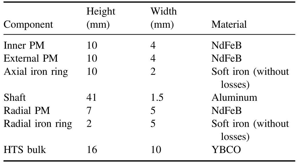
Table 1.Simulation structure parameters of composite bearing.
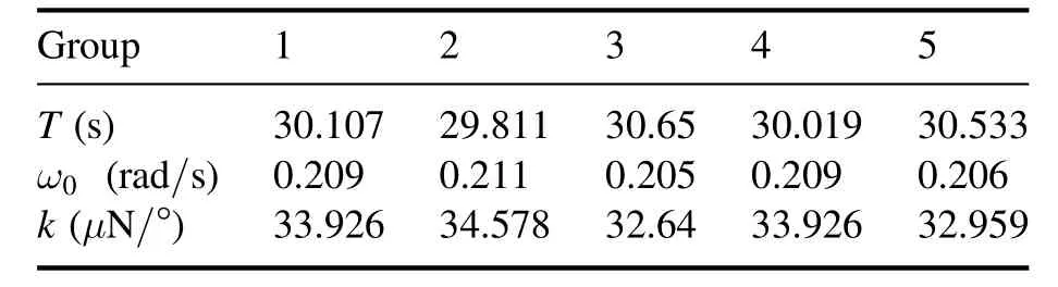
Table 2.The data of five repeated experiments.
Both of the axial and radial bearings are composed of two permanent magnet (PM) and an iron ring, the iron ring is introduced to increase magnetic field density at iron positions.In order to obtain larger levitation force and make the bearing capacity stronger, the thicknesses of PMs are designed as large as possible in the limited space.Furthermore, the authors added an axial PM container to make the diameters of axial PMs match the width of HTS bulk,which can reduce the magnetic flux leakage caused by the coupling of axial and radial PMs magnetic field according to the simulation results.
Figure 5 shows the simulation results of the magnetic flux density.An axial two-dimensional section line along the surface of superconducting stator is drawn to calculate the magnetic flux density, and it is shown that the maximum magnetic flux density is 0.16 T.The two-dimensional crosssections at different gap heights along the radial direction are also drawn and the authors obtain that when the gap height is between 3 mm and 7 mm, the corresponding magnetic flux density is from 0.3 T to 0.1 T.

Figure 1.Schematic diagram of micro thrust measurement.

Figure 2.Ionic liquid electrospray thruster.
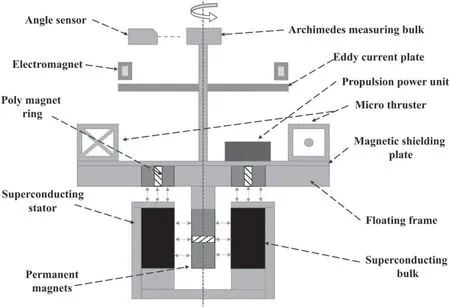
Figure 3.Magnetically levitated testbed with HTS composite bearing.
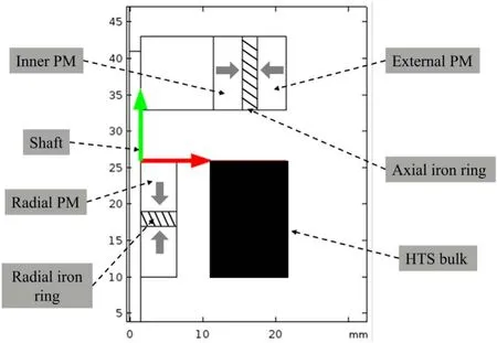
Figure 4.Simulation structure model of composite bearing.
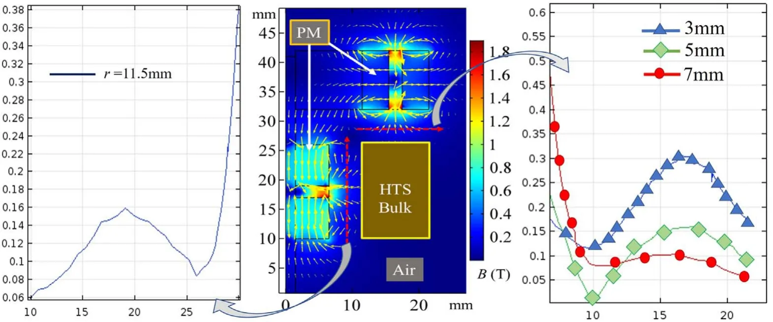
Figure 5.Simulation results of composite bearing.

Figure 6.Composite bearing (left: HTS stator; right: composite PM rotor).
According to parameters analysis obtained from the simulation, the composite bearing is designed and manufactured.The composite bearing mainly includes an arcshaped superconducting bulk,a copper fixing frame,axial and radial PMs and axial PMs container.The physical diagram is shown in figure 6.
Me: How s the salmon2?Server: Fantastic!Me: Does it come with rice?Server: Absolutely!Would a good and a yes have been sufficient? Undeniably!At Starbucks, the smallest coffee you can order is a Tall
3.3.Motion detector
The measurement method used in this work is to use an Archimedes measuring block to convert the angular displacement change of the floating frame into the distance change between the measuring block surface and the laserdisplacement sensor, as shown in figure 7.The method can not only accurately measure the rotation angleθof the floating frame, but also obtain the angular velocity and angular acceleration by the displacement differentiation,without causing any interference to the motion state of floating frame.More importantly,the sensor can also identify the offset of the floating frame in the radial direction.The accuracy of the laser measuring system based on the Archimedes measuring block is 0.03°.
Deflection angle of the floating frame has a linear relationship with the displacement, the measurement equation is designed:
It can be seen that the surface of measuring block should be designed as Archimedes spiral, as shown in the figure 8.
The minimum radius of Archimedes measuring block is 15 mm, and the maximum is 21 mm.The radius increases or decreases linearly with the change of the angle.The angle of Archimedes measuring block changes by 180°, while the linear displacement recognized by the laser displacement sensor changes linearly by 6 mm at the same time, as shown in figure 8(a).
The resolution of laser displacement sensor is 1 μm,which means that the resolution of angular displacement is

4.Experiments and analysis
4.1.Levitation force and stiffness testing
The levitation force and stiffness determine the loading characteristics of composite HTS bearing.The load capacity can be evaluated by the levitation force-displacement curve.Stiffness is used to study the loading stability of HTS bearing and shows the ability that effectively resists the interference to the floating frame.The stiffness can be obtained by differentiating the levitation force-displacement curve,

In general, larger axial bearing capacity means smaller radial stiffness, which requires the authors to make a balance between the bearing capacity and stability, in order to make the testbed have better radial stiffness and low rotating noise.
In the experiment, the HTS bulk was cooled down to 77 K at a distance of 8 mm below the surface of PM rotor to capture magnetic flux and get a large pinning force to obtain radial stiffness, which is also named field cooling (FC) for bulk superconductors.The PM rotor is moved vertically downward at 1 mm s−1until the gap between the axial PM and the HTS bulk is 1 mm and there is no pause for PM rotor moving vertically at 1 mm s−1upward to its initial position.Finally, the levitation force displacement curve of PM rotor can be obtained.Figure 10 shows the experimental process.
4.2.Micro-thrust measurement
The thruster ignition test was carried out in the vacuum condition including a vacuum sub-system and cooling structures.The vacuum sub-system consists of a non-magnetic vacuum chamber and vacuum pump.The minimum vacuum is lower than 10−4Pa.
In order to achieve rapid and uniform cooling for the superconducting bulks, the double-channel conduction-cooling structure shown in figure 11 is designed.The structure includes a cold head of which the minimum temperature can reach 4.2 K, copper heat conduction structure and alumina ceramic cover plate.The heat of the superconductor is transferred from the upper and lower directions to the cold head.This cooling structure greatly improves the cooling speed and effectively guarantees the temperature uniformity of superconducting bulks.
The authors assessed the background noise level of floating frame based on composite superconducting bearing before passive calibration and ignition measurement.Figure 12 shows the oscillation state of the floating frame and power spectrum density (PSD) of the background noise.
Figure 12(a) shows that the floating frame has low zero drift and stable oscillation state, suggesting that the floating frame has a stable oscillation angle around the vertical axis with no radial offset.The data is further processed to obtain the PSD of floating frame, so as to obtain the noise level of different frequency bands, as shown in figure 12(b).Compared with a single axial bearing, the composite bearing designed in this article shows better low-frequency noise characteristics by improving the radial stiffness, as shown in figure 13.

Figure 7.The laser measurement system.

Figure 8.(a) Archimedes spiral diagram, and (b) Archimedes block physical diagram.
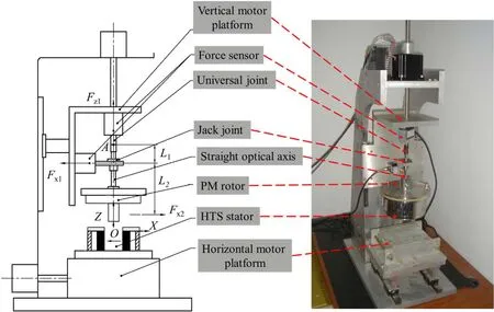
Figure 9.Two-dimensional measuring device.

Figure 10.Experimental process.

Figure 11.Cooling structures and vacuum sub-system.

Figure 12.(a) Oscillation state of floating frame, and (b) power spectrum density of the background noise.
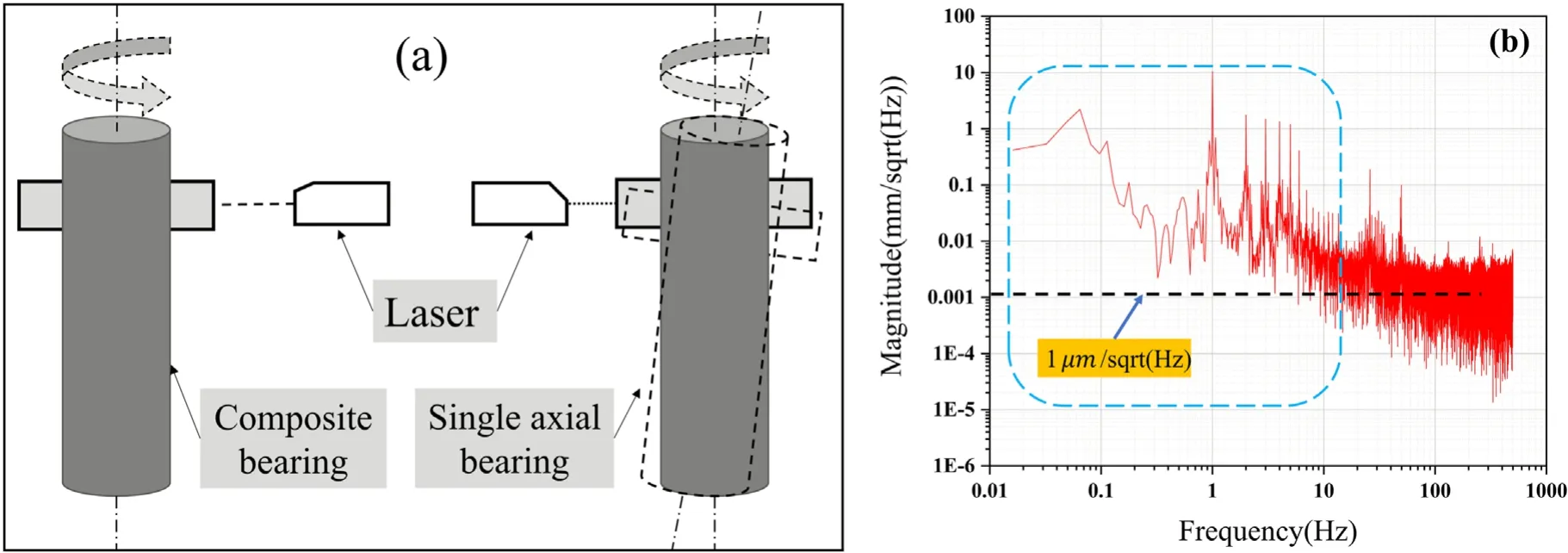
Figure 13.(a) Oscillation state of floating frame based on different bearing, and (b) PSD of single axial superconducting bearing.

Figure 14.Free oscillation curve of the floating frame.
Figure 15.Thruster ignition.
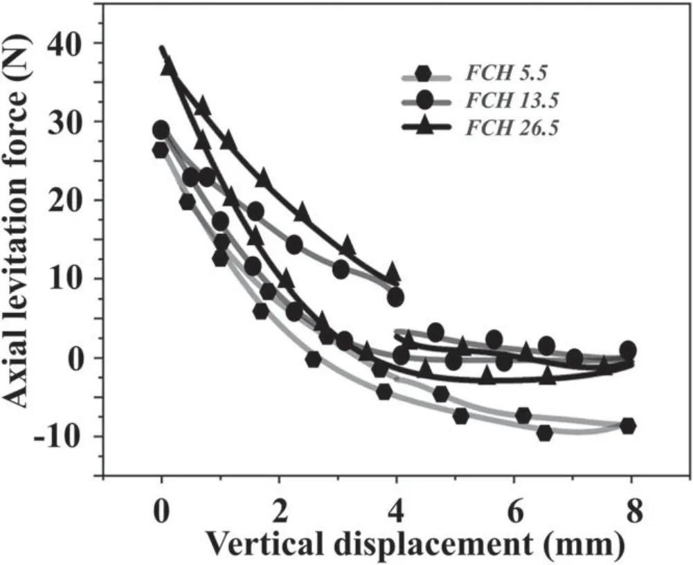
Figure 16.The relationship between levitation force and air gap.
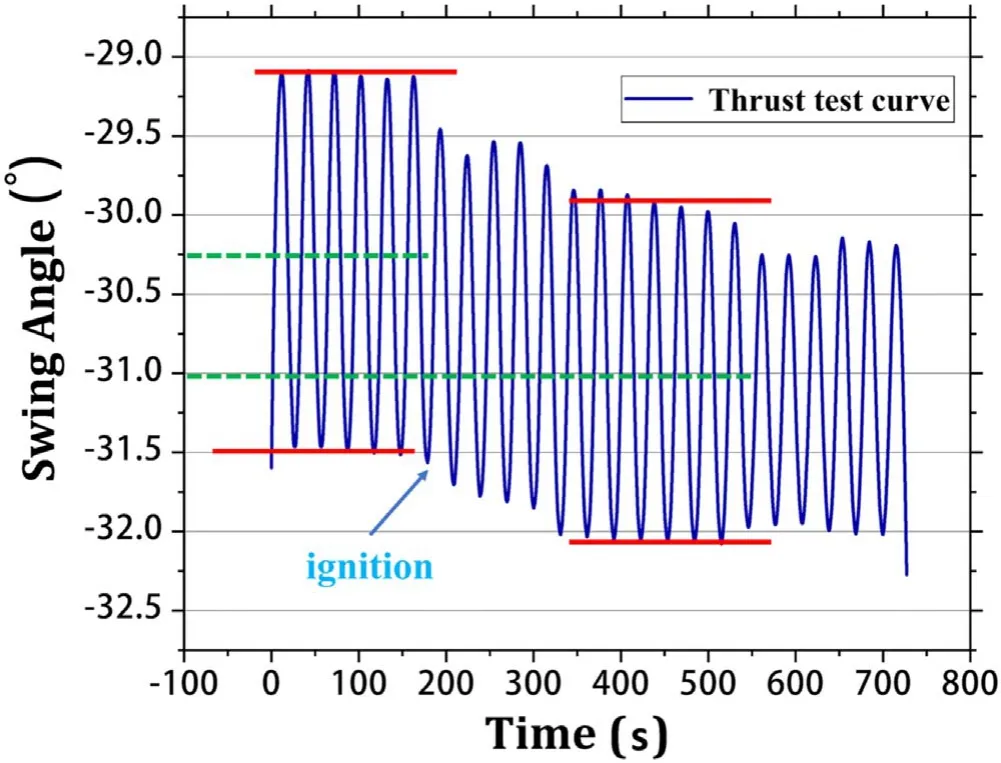
Figure 17.Thruster ignition test.
The PSD of floating frame oscillation based on two different superconducting bearings can be compared in figures 12(b) and 13(b).It can be found that between 1 mHz and 10 Hz, as shown in the blue box, the maximum noise value of floating frame based on the superconducting composite bearing is 1 mm/Hz0.5,while the value is 10 mm/Hz0.5for single axial superconducting bearing.The average noise of superconducting composite bearing is also smaller than that of the single axial bearing above the level of 1 μm/Hz0.5.
Before ignition, the curve in the free oscillation state needs to be captured to calculate the natural periodTand use formula (5) to calculate the restoring torque coefficient.The free oscillation curve is shown in figure 14.
It can be seen from the figure 14 that the curve is sinusoidal, and the amplitude is basically unchanged, indicating that the floating frame experiences extremely low damping and noise in the testing conditions.The curve fitting equation is:

The authors carried out five repetitive calibration tests to obtain five oscillation periods, and calculated the average value via equation (10)

According to equations (9) and (10), the average free oscillation period of floating frame can be obtained as ˜T=30.206 s.
The electromagnetic damper is turned on to weak the oscillation amplitude of the floating frame.The floating frame still has a small oscillation near the equilibrium point after 30 mins.The authors turn off the electromagnetic damper and continue to ignite, while the testbed works in open-loop mode.The displacement change of floating frame is collected via the motion detector.The thruster ignition picture is shown in figure 15.
4.3.Results and discussion
In order to study the influence of FC height on the levitation force, the experiments measured and analyzed the levitation forces when the FC height was 5.5 mm, 13.5 mm, and 26.5 mm (zero FC).The results are shown in figure 16.
It can be seen from the figure 16 that the vertical levitation force curves in the three cases generally have the same trend, which shows the higher FC height brings the larger levitation force.In the horizontal direction, the test results of the radial force show the opposite trend to the vertical levitation force.The results show that the higher FC height causes the smaller radial force.The reason for this phenomenon is that the radial force is mainly the flux pinning force, and the larger axial cooling height will cause a bigger levitation force and but a smaller pinning force.
At the same time, the stiffness characteristics of HTS bearing with FC heights of 5.5 mm,13.5 mm and 26.5 mm are analyzed via the levitation force curves.It can be concluded that the FC height has a great influence on the levitation stiffness of HTS bearing,and the larger FC height leads to the smaller stiffness for both vertical and horizontal directions.
The floating frame can remain stable under the field cold height of 8 mm when the mass is 4 kg,and the corresponding levitation air gap is 2 mm, which can provide about 8 N mm−1stiffness for the floating frame.
After the floating frame is under stable levitation and the oscillation amplitude is suppressed by the damper,the authors turn off the electromagnetic damper and ignite after 200 s,and the thruster continues to ignite for 400 s.It can be clearly seen from the figure 17 that the oscillation equilibrium point of floating frame is changed after ignition.According to the calculation, the change angleθof equilibrium point is 0.75°.The inertia momentIof the floating frame is 0.00445 kg m2,and the equivalent thrust radius is 10 cm.By substituting the above parameters into equations (5) and (2), we can get the thrust was about 25.2μN.
The resolution of this measurement testbed mainly depends on the accuracy of laser displacement sensor according to the low zero drift state of floating frame.The resolution of laser displacement sensor is 1 μm, and the corresponding angular deflection resolution is 0.03°.While the elasticity coefficient ¯kin this article is 33.602 μN/°, so the resolution of the testbed is: 33.602 μN/°×0.03°=1.008 μN.
The authors analyzed the data of five repeated experiments in order to obtain the error of the measurement testbed.The data is shown in table 2.
The standard deviation of the sample with respect to the restoring moment coefficientkcan be determined by equation (11)for a nysatisfies the 3σ principle.

The value of 3Sk is 2.37 μN/°,which can conclude that Thus,it is measured from the free oscillation experiment that the value of=33.602±2.37 μN/°, corresponding thrust is 25.2±1.78 μN.
5.Conclusion
This paper introduces a micro-thrust measuring method based on the magnetic levitation thrust testbed with the key design of an HTS composite bearing, and the new testbed was designed to measure the steady thrust of miniature ion electrospray thruster.An electromagnetic finite simulation was executed to give an optimized design for the HTS composite bearing, the magnetic flux leakage and the electromagnetic interference of the bearing was reduced largely.A 2D measurement device was used to quantitatively analyze the axial and radial levitation forces for the HTS composite bearing.The results show that the HTS bearing has the levitation force larger than 40 N, suggesting that the thrust testbed using the bearing has a load capacity up to 4 kg.Furthermore, the free oscillation curve indicates that the testbed has low noise by introducing HTS composite bearing to increase the radial stiffness.Finally, the floating frame has an obvious response to the ignition of ion electrospray thruster, and the analyzed result is about 25.2μN with an error of 1.78μN.The magnetic levitation thrust testbed also shows a low noise background because of the small radial offset of floating frame during the measurement.
猜你喜欢
杂志排行

Plasma Science and Technology的其它文章
- Special issue on selected papers from CEPC 2020
- Surface treatment of titanium dioxide nanopowder using rotary electrode dielectric barrier discharge reactor
- Application study on plasma ignition in aeroengine strut–cavity–injector integrated afterburner
- Microanalysis of a ductile iron by microchip laser-induced breakdown spectroscopy
- Study on water treatment effect of dispersion discharge plasma based on flowing water film electrode
- Decontamination of infected plant seeds utilizing atmospheric gliding arc discharge plasma treatment