Transient Response of Twisted Wire Pairs llluminated by HEMP
2021-10-11YouJieYanLinMengShouLongZhangJinHongWeiZhanJunLiuBinWenWang
You-Jie Yan | Lin Meng | Shou-Long Zhang | Jin-Hong Wei | Zhan-Jun Liu |Bin-Wen Wang
Abstract—In this paper,the time domain characters of the response of twisted wire pairs (TWPs) excited by the high-altitude electromagnetic pulse (HEMP) have been proposed.The finite different time domain transmission line model (FDTD-TLM) method,which we have proposed previously,is used to calculate the terminal response of TWP.It shows that the time domain response includes two stages:The transient stage and damped stage.The transient stage is the key point of the coupling and protecting research.The influence factors of the transient stage have been analyzed.In the end,we obtain the changes of the induced voltage when the incident wave parameters and TWP parameters change.
1.lntroduction
Twisted wire pairs (TWPs) are often selected as the transmission medium of the modern information system,which have good anti-interference ability,low loss,and low costs.It is widely used in the network system,bus system,communications system,power system,etc.The field to line coupling is the main coupling path of high-altitude electromagnetic pulse (HEMP)[1]-[4].The energy of HEMP is coupled through the cable into the system,causing the system failure[5]-[9].Research on the coupling of HEMP to TWP is of great significance to improve the information system’s immunity to HEMP[10]-[13].
The traditional research on the field-to-TWP problem is mostly based on the frequency domain method.The coupling of TWP with the external electromagnetic field is studied through the expansion of the transmission line model (TLM)[10]-[12].In recent years,the coupling of TWP bundles[13],[14]and the coupling of random parameter TWP are mainly concerned[15]-[17].
Considering the transient property of HEMP,the time domain characteristics of field-to-TWP need to be studied.Celozziet al.[18]analyzed the time domain characteristics of field-to-TWP by the time-to-frequency transformation with the calculation results in the frequency domain.Yuanet al.[19]analyzed the frequency domain calculation model,transformed the frequency domain source term to the time domain,and obtained the time domain (the simulation program with the integrated circuit emphasis (SPICE) model of field-to-TWP).Tatematsuet al.[20]established the three-dimensional (3D) finite different time domain (FDTD) method and solved the coupled voltage on TWP based on the Agrawal model.But this method is complex and difficult to use in calculation.Yanet al.[21]proposed the finite different time domain transmission line model (FDTD-TLM)method,which realized the time domain solution of TWP coupled with the electromagnetic field and increased the computational efficiency under the same hardware condition.
This paper briefly reviews the FDTD-TLM method and algorithm of field-to-TWP coupling.With this method,the time domain characteristics of the terminal voltage response of TWP illuminated by HEMP are intuitively presented.In addition,the effects on the terminal response caused by the parameters variation of the incident plane wave and TWP are analyzed.The research results will help to understand the physical process of HEMP interference and protection.
2.FDTD-TLM Method of Field-to-TWP Coupling
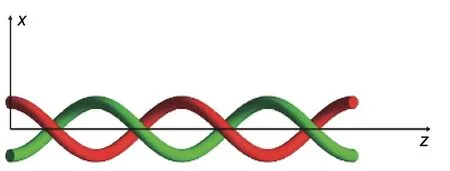
The structure of TWP is considered to be an ideal bifilar helix[5],[7]as shown inFig.1.Its structure equation is


Fig.1.Structure of TWP.
wherelis the length,pis the pitch,andsis the separation distance between the wires.The quantityαis the TWP rotation parameter defined by

For linear TWP,its structure exists in the 3D space.But according to the structure equation of TWP,its 3D structure can be established by one parameter.When TWP is placed along thezaxis,the distribution of TWP in the space domain depends on the length.
When establishing the FDTD-TLM model of TWP,we introduce the TWP equation into the electromagnetic field analysis of a two-paralleled conductor line,and obtain the transmission line (TL)equation only containing the parameters of the incident electric field.The detailed derivation was given in [21],and we only introduce the main conclusions.The equations of the FDTD-TLM method are as follows:


whereVFandIFare the distributed voltage sources and distributed current sources;L,C,R,andGare the inductor,capacitor,resistor,and conductance per unit length,respectively;V(z,t) andI(z,t) are the voltage and current along the line;Eincis the electric field vector of the incident field,which is determined in the absence of TWP,(0,0,z,t) and(0,0,z,t) ;andare position-dependent unit vectors.
In the case of uniform plane-wave incidence,the source term in the transmission line equation above can be approximated as follows:

It is complex to solve the equations above.By discretizing the equation group with the timetand the lengthz,the equations can be solved iteratively through FDTD.

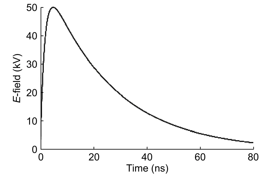
Fig.2.Waveform of E1 part of HEMP.
3.Transient Response of TWP Excited by HEMP
The model of TWP under analysis is 24-AWG(American Wire Gauge).The wire pitchp=0.11 m,the radiusr=0.25 mm,the separation distances=1.28 mm,the lengthl=10p,and the relative dielectric constantεr=1.6[11].For simplicity,the dielectric material is assumed lossless and homogeneous,the per-unit-length inductance is 0.64 μH/m and the per-unit-length capacitance is 28.0 pF/m.The characteristic impedance of TWP is 150 Ω,the loads are considered resistive terminations,and the impedance of bothZSandZLis 150 Ω.The twisted pair is placed forward along thez-axis.

Fig.3.Definition of the parameters characterizing the incident uniform plane wave.
The E1 part of HEMP recommended on International Electrotechnical Commission (IEC) 61000-2-9 is chosen to excite TWP,as shown inFig.2.The pulse rise time is 2.5 ns,the pulse width is 23 ns,the falling time is 55 ns,and the peak electric field intensity is 50 kV/m.Parameters of the excited plane wave are defined as shown inFig.3.The propagation direction and the electric field polarization direction of the plane wave are perpendicular to TWP,i.e.,ϕp=0°,θE=90°,andθP=90°.The corresponding electric field vectors areex=1,ey=0,andez=0,and the propagation vectors arekx=0,ky=1,andkz=0.
The terminal voltage response of TWP obtained by FDTD-TLM is shown inFig.4.At the same time,Computer Simulation Technology (CST) Aktien Gesellschaft Microwave Studio is also used to model and calculate the simulation above.When the grid reaches three million,the calculation result tends to be stable,and the terminal voltage response is also shown inFig.4.The result of FDTD-TLM is in agreement with the result of full-wave electromagnetic simulation based on the finite integration technique (FIT) of CST.The calculation efficiency is increased by more than 100 times under the same hardware conditions.
The result shows that the coupled voltage is mainly composed of the transient stage and the damped stage.The transient stage is characterized by the high amplitude oscillation.The peak-to-peak amplitude of the oscillation is about 3.4 V;the period of oscillation is about the propagation time when the coupled voltage spreads through one pitch;the number of oscillation is the number of pitches.The damped stage is mainly characterized by the attenuation of the oscillation envelope which decays exponentially.In the case above,the oscillation amplitude is attenuated to less than 0.1 V in 1 ns.

Fig.4.Voltage induced on the terminal of TWP.
4.lnfluence of lncident Parameters on Coupled Voltage

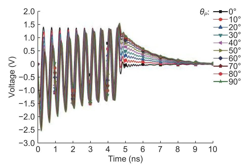
Fig.5.Voltage induced on the 150 Ω terminal impedance at z=0 of TWP with θE=0° as the incident angle θP changes.
In this section,the influence of the plane wave with different incident directions and different polarization directions on the characteristics of the interference voltage at the terminal is studied.
1) We study the influence of the plane wave with different incident directions on the coupled interference signal,when the electric polarization direction is paralleled with TWP and the magnetic field polarization direction is perpendicular to TWP,i.e.,ϕP=0°,θE=0°,andθPchanges from 0° to 90°.Fig.5shows the variation of the coupled voltage on the terminalZSalong with the increase of the incidence angle.
The results show that,with the increase of the incident angleθP,the peak-to-peak value of the coupled oscillation voltage in the transient stage decreases,but the change is not obvious.The envelope of the coupled oscillation voltage presents an exponential trend,and the trend is more obvious with the increase of the incident angle.For the damped stage,the initial amplitude of the attenuation oscillation increases along with the increase of the incidence angleθPand reaches the maximum at 90°.
2) The study of the influence of different incident directions on the interference signal at the terminalZSis conducted,when the electric polarization direction is perpendicular to TWP and the magnetic polarization direction is paralleled to TWP,i.e.,ϕP=0°,θE=90°,andθPranges from 0° to 90°.The results are shown inFig.6.
The result shows that with the increase of the incident angleθP,the amplitude of the coupled voltage in the transient stage is almost unchanged,but the center of the envelope changes from negative to zero.With the increase of the angleθP,the initial amplitude of the attenuation oscillation gradually decreases at the damped stage.
3) We study the influence of different incident directions on the coupled interference signal,when the electric polarization direction is paralleled with thex-axis,i.e.,θP=90°,θE=90°,andϕPranges from -90° to 90°.Fig.7shows the interference voltage on the terminalZSat the beginning.
The results show that the coupled voltage on the loadZSat the beginning is greatly changed whenϕPchanges both from -90° to 0° and from 0° to 90°.At the transient stage,the amplitude of the coupled voltage,the oscillation period,and the total duration of oscillation decrease,whenϕPvaries from -90° to 0°.AsϕPvaries from 0° to 90°,the amplitude of the coupled voltage decreases,and the oscillation envelope shows a decreasing trend,but the total duration and the period of oscillation remain unchanged.At the damped stage,it has little influence on the coupled voltage on the loadZSwith the two cases above.

Fig.6.Voltage induced on the 150 Ω terminal impedance at z =0 of TWP with θE=90° as the incident angle θP changes.

Fig.7.Voltage induced on the 150 Ω terminal impedance at z =0 of TWP with θP=90° and θE=90° as the incident angle ϕP changes:(a) from -90° to 0° and (b) from 0° to 90°.

Fig.8.Voltage induced on the 150 Ω terminal impedance at z =0 of TWP with θP=90° and θE=0° as the incident angle ϕP changes:(a) from -90° to 0° and (b) from 0° to 90°.
The main reason is that with the variation ofϕP,the time delay in the propagation of the plane wave to each twisted pitch changes,resulting in the variation of the propagation time difference of the coupled voltage from each twisted pitch to the terminal.When the time delay in the propagation of the plane wave to each twisted pitch is positive (i.e.,ϕPchanges from -90° to 0°),the propagation time difference of the coupled voltage from each twisted pitch to the terminal is enlarged.This will lead to two results.One is the longer period of oscillation and the other is the larger amplitude of the coupled voltage.When the time delay in the propagation of the plane wave to each twisted pitch is negative (i.e.,ϕPchanges from 0° to 90°),the relative propagation delay between the coupled voltage of each twisted pitch exists,but the propagation time difference of the coupled voltage from each twisted pitch to the terminal remains unchanged.This will lead to the gradual decrease of the voltage amplitude superposed by the coupled voltage of each twisted pitch,but the oscillation period is still along with the propagation time of the voltage wave through one twisted pitch.
Meanwhile,considering the symmetry of the terminal at both ends,the analysis results show that the coupled voltage on the terminal at both ends is very different under the excitation of HEMP.
4) We study the influence of different incident directions on the coupled interference signal,when the magnetic polarization direction is paralleled with thex-axis,i.e.,θP=90°,θE=0°,andϕPranges from -90° to 90°.Fig.8shows the induced voltage signal on the terminalZSat the beginning.
The results show that the coupled voltage on the beginning terminalZSis greatly changed,whenϕPchanges from -90° to 0° and from 0° to 90°.WhenϕPchanges from -90° to 0°,the amplitude of the coupled voltage at the transient stage decreases;the oscillation envelope ascends,but the ascending trend becomes slow;the oscillation period and total duration of oscillation decrease.AsϕPchanges from -90° to 90°,the amplitude of the coupled voltage at the transient stage continues decreasing;the ascending trend of the oscillation envelope decreases until the descending trend appears.The changes above have also contributed to the change of the time delay in the propagation of the plane wave to each twisted pitch.
5.lnfluence of TWP Parameters on Coupled Voltage
The parameters of TWP illuminated by HEMP will also affect the coupled voltage on the terminal.This section mainly concerns the influence of the pitch and terminal impedance changes of TWP on the coupled voltage characteristics.

Fig.9.Voltage induced on the 150 Ω terminal impedance at z =0 of TWP as the twist period changes.
First,the influence of the pitch changes of TWP on the coupled voltage is studied.The excited plane wave propagates along they-axis and illuminates to TWP perpendicularly from the side.The electric field polarization direction is perpendicular to TWP.Keeping the length of TWP to 10p,we calculate the coupled voltage on the terminalZSwith the twist pitchpchanging from 0.11 m to 0.99 m.The results are shown inFig.9.
The results show that with the increase of the pitch,the oscillation amplitude at the transient stage correspondingly changes from 3.5 V to 32.1 V.The oscillation period also increases,mainly due to the extension of the propagation time of the coupled voltage through one twisted pitch.
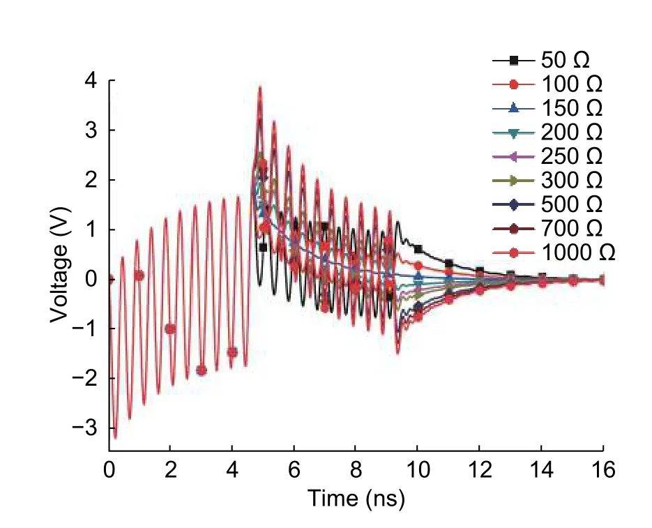
The influence of the terminal impedance changing from 50 Ω to 1 kΩ on the coupled voltages is analyzed.The coupled voltage on the terminals at the beginning and the end are given inFig.10andFig.11,respectively.

Fig.10.Voltage induced on terminal impedance at z =0 of TWP as terminal impedance changes.

Fig.11.Voltage induced on terminal impedance at z =L of TWP as terminal impedance changes.
The results show that with the increased impedance of the terminal,the amplitude of the interference voltage on this terminal increases gradually in both stages.On the other terminal,the characteristics of the coupled interference voltage in the transient stage keep the same.Thereafter,the reflected equal amplitude oscillation from the beginning terminal coincides with the damped oscillation.It is shown that the envelope of the oscillation is exponentially attenuated,and the oscillation amplitude almost satisfies the condition of impedance reflection.
6.Summary
The time domain characteristics of the response of TWP excited by HEMP have been presented in this paper.The interference voltage on TWP is mainly composed of the transient stage and the damped stage.The transient stage is characterized by the large amplitude oscillation.The amplitude of the voltage in the transient stage is about 3.4 V.The period of the transient stage is about equal to the propagation time for the coupled voltage spreading through one pitch;the number of oscillation is the number of the pitches.The transient stage is the key point of coupling and protection research.
The changes of the incident direction and the polarization direction will affect the envelope,amplitude,and period of the transient stage.With the pitch increases,the oscillation amplitude at the transient stage correspondingly changes from 3.5 V to 32.1 V.With the increased impedance of the beginning terminal,the amplitude of the coupled interference voltage increases gradually on the beginning terminal.
The results are helpful to deepen the understanding of the electromagnetic coupling and electromagnetic protection of TWP illuminated by HEMP.
Disclosures
The authors declare no conflicts of interest.
杂志排行
Journal of Electronic Science and Technology的其它文章
- Recent Progress in Chiral Absorptive Metamaterials
- Resolving Deep Sub-Wavelength Scattering of Nanoscale Sidewalls Using Parametric Microscopy
- Dual-Mode Terahertz Extended lnteraction Oscillator Driven by a Pseudospark-Sourced Sheet Electron Beam
- Diagnosis of Dental Caries Using Terahertz Technology
- Single-Bit Comparator in Quantum-Dot Cellular Automata (QCA) Technology Using Novel QCAXNOR Gates
- Quasi-Z Source lnverter Control of PV Grid-Connected Based on Fuzzy PCl
