Dual-Mode Terahertz Extended lnteraction Oscillator Driven by a Pseudospark-Sourced Sheet Electron Beam
2021-10-11JieXieXueSongYuanLiangZhangAdrianCrossHuaBiYinQingYunChenTongBinYangXiaoTaoXuYangYanLinMeng
Jie Xie | Xue-Song Yuan | Liang Zhang | Adrian W.Cross | Hua-Bi Yin |Qing-Yun Chen | Tong-Bin Yang | Xiao-Tao Xu | Yang Yan | Lin Meng
Abstract—A terahertz dual-mode extended interaction oscillator (EIO) driven by a pseudospark-sourced sheet electron beam (SEB) was presented.The major advantages of the newly developed circuit include 1) high-density SEB interacting with the TM11 and TM31 modes,respectively,and 2) high output power of over 1 kW at the subterahertz frequency range.Two different types of 2π modes and their output characteristics were studied,and the circuit was optimized to ensure efficient outputs of two standing-wave modes.The three-dimensional (3D)particle-in-cell (PIC) simulation predicts the maximum output power of 1.3 kW with the 3-dB bandwidth of~0.5 GHz at 303 GHz when operating at the TM11 mode,and 3.18 kW with the 3-dB bandwidth of~0.85 GHz at 364 GHz when operating at the TM31 mode.
1.lntroduction
In the recent decades,high-power radiation sources at the millimeter waves and terahertz (THz) radiation frequency bands from 100 GHz to 1 THz have gained significant interest due to their numerous exciting applications,such as broadband wireless and high data rate communications,high resolution radar and imaging,and biomedical and plasma diagnostics[1]-[6].Driven by these applications,the THz radiation sources with high output power had made great progress.Among various THz radiation sources,vacuum electronic devices (VEDs) are intrinsically superior with handling high power or high power density due to the electrons moving in vacuum without scattering[2],[7],[8].The sheet electron beam extended interaction oscillator (SEBEIO),as an important kind of VEDs achieving high output power and maintaining a compact structure,has gained considerable attention as a promising THz oscillation source due to its feasibility,stability,and high gain per unit length[2],[9].In the THz frequency band,one of the major factors limiting the development of THz devices is the maximum electron beam current density at the interaction region.In our design,a pseudospark-sourced(PS) electron beam was used to drive SEBEIO because of its high current density (108A/m2),high brightness(1012A/(m2rad2)),low vacuum requirements,and its propagation with no need for any external focusing magnetic fields[10]-[14].
A number of SEBEIO experiments have been reported.For example,a W-band extended interaction klystron (EIK) was reported by Pasouret al.,which produced 7.5-kW output power.It was driven by a 20-kV,4-A sheet beam and the efficiency was~17%[15].At University of California,Davis,a W-band sheet beam klystron with 10-kW output power,20-ms pulse duration,and 17-dB gain was presented[16].An extended interaction oscillator (EIO) with~10-W continuous-wave (CW) output power operated at 220 GHz to 270 GHz and an EIK with 25-W pulsed power operated at 250 GHz to 276 GHz have been designed by Communication &Power Industries,Inc.[17].The high-power W-band SEBEIO with 6-kW maximum output power driven by the 47.2-kV and 2.1-A sheet electron beam (SEB) and more than 1.2-kW average power has been designed and tested by Wanget al.at University of Electronic Science and Technology of China[18].The researchers at University of Strathclyde presented the SEBEIO output power of over 10 W at a frequency of~0.2 THz and the W-band SEBEIO with the peak output power up to 1.2 kW[19],[20].As discussed in all of the above EIOs and EIKs,they have achieved excellent performance in a single frequency band.However,to develop SEBEIO using the same circuit to work in dual frequency bands is significantly beneficial for reducing the size,cost,and weight of THz sources.This paper introduces the design of dual-mode SEBEIO,which works at both 0.30 THz and 0.36 THz with the tuning bandwidth of 0.50 GHz and 0.85 GHz,respectively,and peak power of more than 1.3 kW.
2.Pseudospark-Sourced Sheet Electron Beam (PS-SEB)
In the recent decades,the PS-generated high-density and energetic-pulsed electron beam has attracted significant interest due to its potential and growing applications in the areas of high-power radiation generation,extreme ultraviolet (EUV) sources,intense X-rays,free electron masers,and so on[11]-[14],[19]-[28].The PS discharge is a self-sustained,transient,and axially symmetric discharge at the low-pressure (50 mTorr to 500 mTorr) gas conditions.It has the ability to produce the electron beams combined the highest current density and brightness with low emittance of 15 mm·mrad,fast current rise up to 1012A/s,and high power density of~1 019W/c m2,which is catered to the requirement for high-power sources of millimeter waves and THz radiation,as well as accelerators,such as backward wave oscillators (BWOs),EIOs,and free-electron lasers (FELs)[29]-[31].In recent years,the PS electron beam achieved further progress and various pencil PS discharge electron beams have been investigated by the particle-in-cell (PIC) simulations and experiments[32]-[36].
Nevertheless,one of the major factors limiting high-power vacuum microwave radiation sources to higher frequencies is the need of transporting beams with higher current density,due to the decrease of highfrequency circuit transverse dimensions with the wavelength.As the frequency of VED increasing to 100 GHz or beyond that,the beam diameter has to be approximately one-tenth of the wavelength or less in pencil-beam VEDs.While,the use of SEB can overcome this difficult owing to its larger cross-sectional dimensions.Compared with the pencil beam,the advantage of SEB is that the space charge effect is small and a higher current can be achieved by increasing the beam width,which helps to increase the output power.It is a challenge for the thermionic cathode to generate a sufficiently high-perveance and uniform beam,since it needs a complicate focusing system to confine SEB.However,it is much simpler in a PS discharge system since a plasma channel formed in the system can confine SEB and has no need for an external magnetic field.In the experiment,a post-acceleration modulator with a cross-sectional size of 1.00 mm × 0.17 mm of SEB was used,and PS-SEB with a peak current of 21.5 A was measured without an external focusing magnetic field[20].PS-SEB with the current density of~1 kA/cm2has been generated using a sheet beam plasma cathode electron gun[37].The influence of geometrical design parameters on the high current density PS-SEB has been analyzed by the PIC simulation models and experiments[38],[39].In this article,SEB generated by PS is used to drive the dual-mode SBEIO structure.In our design of the PS discharge system,it has a four-gap PS discharge setup which consists of a hollow cathode (HC) with a central hole and an anode with an aperture to extract the electron beam,as shown inFig.1.The anode and HC are separated by the dielectric insulators.The PS discharge occurs under suitable low pressure (typically 50 mTorr to 500 mTorr) in the system,as HC is applied with a negative high voltage and the anode is grounded.In the process of the PS discharge,an electron beam with a very large current can be generated.When the high current density and brightness beam propagates through the anode and the interaction circuit,the front edge of the beam ionizes the background gas and generates a plasma channel.Subsequently,beam electrons expel some of the plasma electrons,while the heavier ions remain fixed.Therefore,a positive ion channel is formed to focus the PS electron beam.PS-SEB can be extracted using a collimator with a rectangular aperture placed at the end of the anode.The rectangular aperture of the collimator should be located at the same axial center as the cylindrical aperture of the anode.
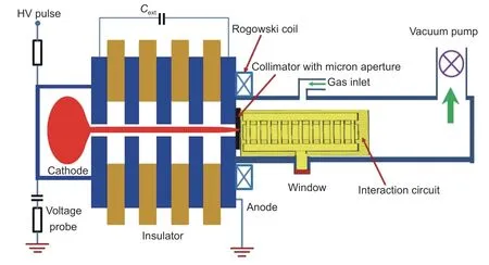
Fig.1.SBEIO composed of a four-gap PS discharge system and the interaction circuit.
3.Design of the SEBElO Circuit
The SEBEIO circuit composes of eleven gaps and two symmetrical coupling cavities on both sides of the structure,as shown inFig.2.A 0.90 mm × 0.19 mm rectangular beam tunnel passes through the center of the slots and intersects with the slow-wave structure.It combines the advantages of traveling-wave tubes and klystrons and has the capacity of handling high output power in the millimeter-wave and THz-frequency regimes.EIO,typically,works at the fundamental mode (TM11mode),since it is the easiest mode to achieve the start-oscillation condition[20],[30],[40].While in recent years,EIO working at the high-order mode has become more and more attractive due to its higher beam power and larger power capacity[41]-[43].
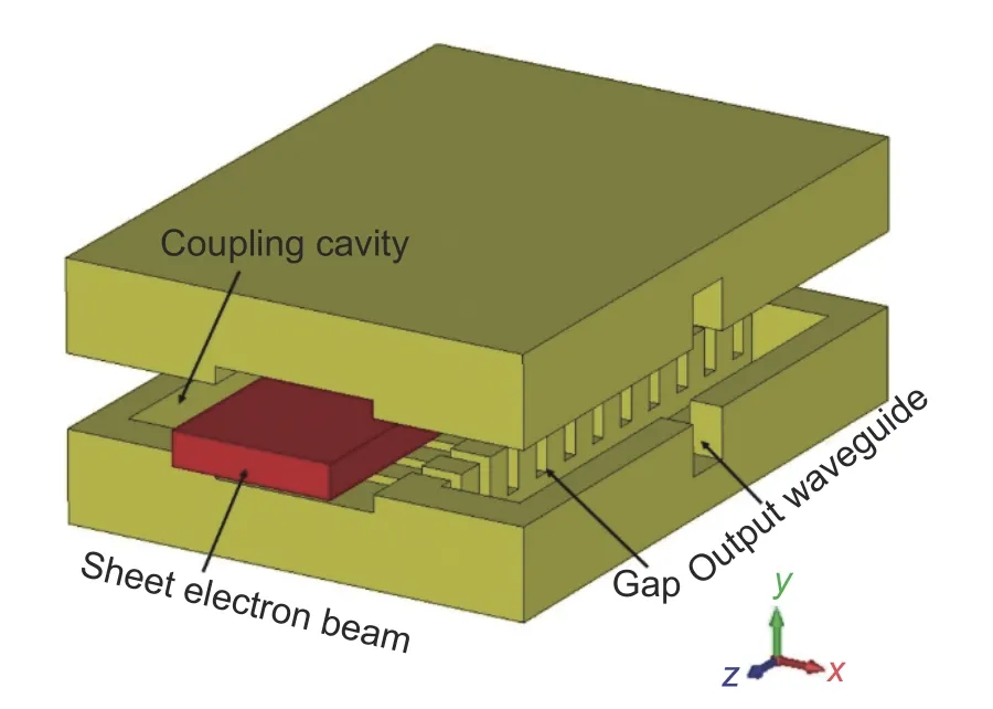
Fig.2.Schematic drawing of the SEBEIO circuit with eleven gaps.
3.1.Mode Analysis
The three-dimensional (3D) SEBEIO model is shown inFig.2.The ladder cavity is a periodic standing-wave circuit along the longitudinal direction.Based on the distribution pattern of the axial electric field in the cavity along the transverse direction,the resonant modes of the ladder cavity are usually named as TMn1and the indexnis determined by the variation in the distribution pattern of the axial electric field along the transverse direction.The axial electric field distributions of the fundamental mode TM11and the high-order mode TM31at the cross section are shown inFig.3.TheEzfields in the TM11and TM31modes are unidirectional and concentrating at the beam area so that the interaction with the electron beam is effective.The beam-mode coupling is determined by the characteristic impedanceR/Q,expressed asR/Q=/2ωW,whereRis the equivalent resistance of cavity,Qis the quality factor,ωis the resonant angular frequency,andWis the stored energy in the cavity,which is a measure ofEzfields interacting on the electrons.The TM31mode provides a stronger electric field concentrating at the tunnel area as well as highR/Q,as shown inFig.3.Table 1lists the frequencies,inherent quality factorsQ0,and characteristic impedancesR/Qof the cavity with different modes.R/Qindicates the strength of the interaction between the electron beam and the high-frequency field in the cavity.A cavity with higherR/Qhas the potential to achieve higher output power.The electric field of the 2πmode is in the same direction in each gap as shown inFig.4,which contributes to a higherR/Qvalue.The 2πmode also provides the electric field with the same direction in each gap for sufficient beam-wave interactions,as shown inFig.5.The TM31-2πmode has the highestR/Q,which is beneficial for SEBEIOs when operating at a high-order mode.Meanwhile,the 2πmode corresponds to the largest fundamental spatial harmonic and consequently has the largest structure dimension along the axial direction[44],[45].

Table 1:Basic parameters of the eigenmodes
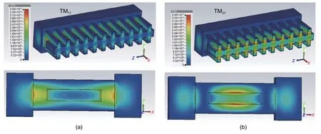
Fig.3.Electric field magnitude for (a) TM11 mode and (b) TM31 mode at the cross section.
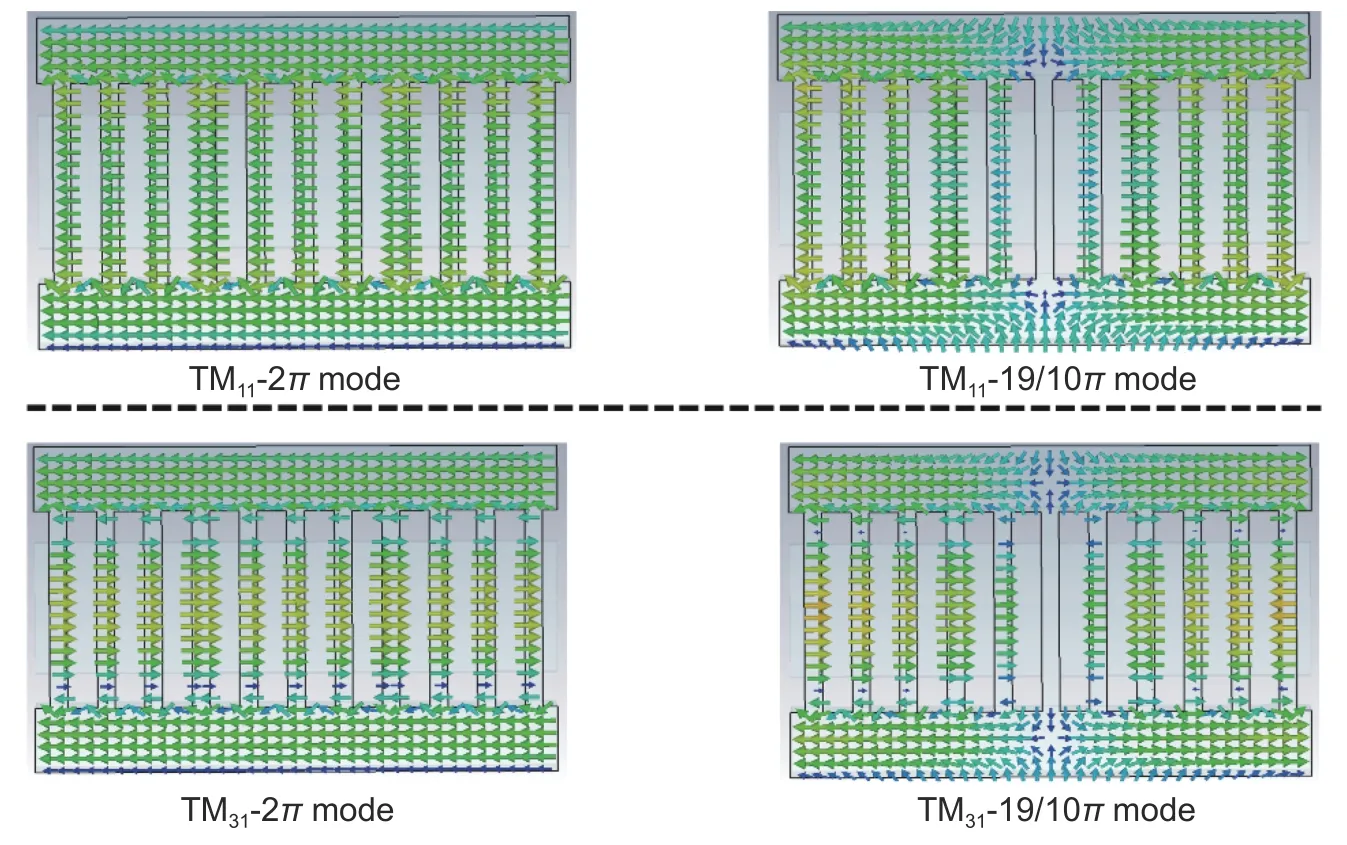
Fig.4.Ez-field distributions of TM11-2π,TM11-19/10π,TM31-2π,and TM31-19/10π modes along the z axis.

Fig.5.Normalized Ez distributions along the z axis of (a) TM11-2π and TM11-19/10π modes and (b) TM31-2π and TM31-19/10π modes.
3.2.Dispersion Characteristic
The key issue for EIO operating in a dual-mode condition is the mode competition.An effective method is to make the frequency interval between the operating modes wide enough.Due to the limited periodic structure of the multigap resonant cavity,the dispersion curve consists of a series of discrete frequency points.The dispersion curve of the designed radio frequency (RF) circuit computed by Computer Simulation Technology (CST) Microwave Studio is shown inFig.6.It is an effective approach to identify the possible mode competition and self-oscillation.The red curve with dot markers represents the TM11mode,and the blue curve with triangular markers represents the TM31mode.The operating voltages of the TM11-2πand TM31-2πmodes are 18.5 kV to 22.5 kV and 27.5 kV to 34 kV,respectively,and the synchronous beam voltages are 20 kV and 30 kV,respectively,as shown inFig.6.The operating voltage of the TM11-2πmode is smaller than that of the TM31-2πmode.As shown inFig.6,the 22.5-kV beam line is far away from the TM31-2πmode point so the competition between these two 2πmodes can be suppressed.However,the 30-kV beamline intersects with the TM11-17/10πmode,which indicates the mode competition between these two modes may occur as the oscillation startup condition is satisfied.
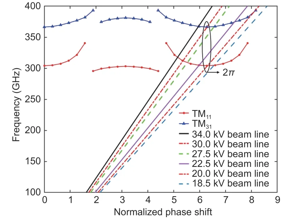
Fig.6.Dispersion curve of the SEBEIO circuit.
The normalizedEz-field distribution of the TM31-2πmode along the beam tunnel is significantly stronger than that of the TM11-17/10πmode,as shown inFig.7 (a).Through estimation using the axial electric field,the characteristic impedanceR/Qof the TM31-2πmode is about 10 times than that of the TM11-17/10πmode,as shown inTable 1.The normalizedEz-field distributions of the TM31-2πand TM11-17/10πmodes along the cross-section are illustrated inFig.7 (b).In the beam tunnel area,theEzfield strength of the TM31-2πmode is stronger than that of the TM11-17/10πmode.Reflected from the results of theR/Qvalues and field distributions of these two modes,the competition between the TM11-17/10πmode and the TM31-2πmode is hard to be excited.
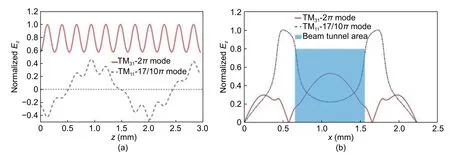
Fig.7.Ez-field distributions of the TM31-2π and TM11-17/10π modes along (a) the beam tunnel direction and (b) the cross section of cavity.
4.PlC Simulation
To validate our design,the 3D PIC simulation was used to demonstrate the performance of the dual-mode SEBEIO.As the operating frequency of VEDs increasing up to the THz range,the Ohmic loss caused by the metal material has a significant impact on the performance.The copper conductivity at the THz frequency range is much smaller than that in the direct current (DC) case.The nonideal surface losses at the THz frequency caused by surface roughness have been reported in [46].In our simulation,the conductivityσof the background material was set as 1.1×10⁷S/m (<σCu/5,σCu=5.8×107S/m for copper),taking into consideration the Ohmic loss.A beam current of 3 A with the voltages of 24 kV and 37 kV is respectively injected into the interaction circuit.A stable output signal with 51.8 V/79.4 V (equivalent to output power of 1.34 kW/3.15 kW) is obtained at 303.4 GHz/364.5 GHz,respectively,as depicted inFig.8.TheEz-field distributions along thezaxis demonstrate SEBEIO can operate at the TM11-2πand TM31-2πmodes without mode competition,which agrees well with the above theoretical analysis of the circuit’s dispersion curve.Fig.9shows the output power,frequency,and the starting oscillation time versus the voltage.It predicts that the output power changes from 0.94 kW to 1.34 kW in the voltage range between 23.5 kV and 26.0 kV for the TM11-2πmode,and the output power changes from 1.58 kW to 3.15 kW in the voltage range between 35 kV and 40 kV for the TM31-2πmode.The 3-dB tuning bandwidth is about 0.50 GHz and 0.84 GHz for the TM11-2πand TM31-2πmodes with the maximum output power up to 1.34 kW and 3.18 kW,respectively.The simulation results show that the designed SEBEIO is stable for the TM11-2πand TM31-2πmodes operation.

Fig.8.Simulation results:Output voltage signals (inset:Trajectory of electrons),frequency spectra,and the electric field distributions at the operating voltages U=24 kV (upside) and U=37 kV (downside).
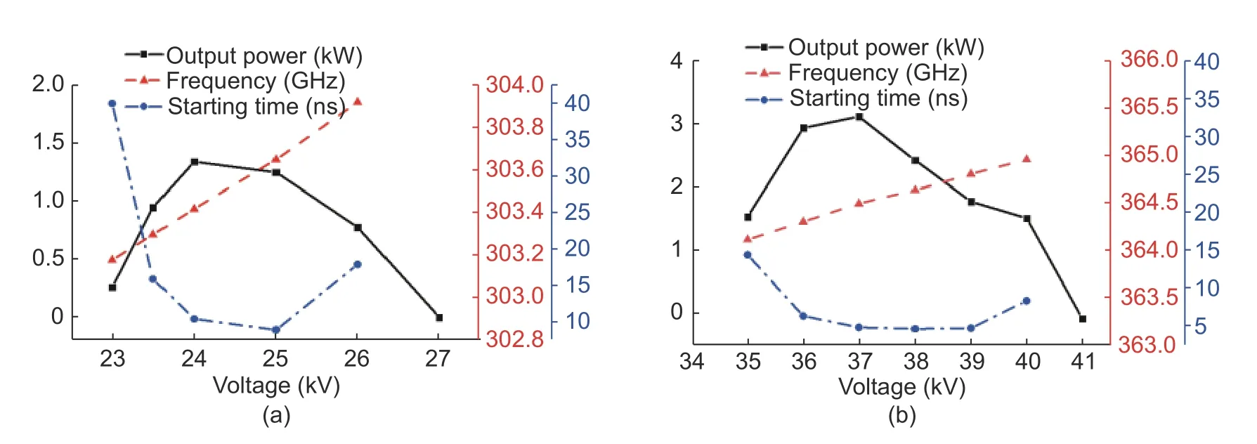
Fig.9.Output power,frequency,and the oscillation starting time variations with the operating voltage:(a) TM11-2π mode and (b) TM31-2π mode.
5.Conclusions
In this paper,the THz dual-mode EIO driven by PS-SEB was presented.Based on the analysis of the dispersion curve of the slow-wave structure and the electric field distribution in the cavity,the mode competition was studied.The PIC simulation predicts stable dual-mode operation,with the maximum output power of 1.34 kW,3-dB bandwidth of~0.50 GHz at 303.4 GHz when operating at the TM11-2πmode,and the maximum output power of 3.18 kW,3-dB bandwidth of~0.84 GHz at 364.5 GHz when operating at the TM31-2πmode,respectively.Our next step is to fabricate,assemble,and measure the designed dual-mode SEBEIO to verify the simulation results experimentally.
Disclosures
The authors declare no conflicts of interest.
杂志排行
Journal of Electronic Science and Technology的其它文章
- Recent Progress in Chiral Absorptive Metamaterials
- Resolving Deep Sub-Wavelength Scattering of Nanoscale Sidewalls Using Parametric Microscopy
- Diagnosis of Dental Caries Using Terahertz Technology
- Single-Bit Comparator in Quantum-Dot Cellular Automata (QCA) Technology Using Novel QCAXNOR Gates
- Quasi-Z Source lnverter Control of PV Grid-Connected Based on Fuzzy PCl
- Transient Response of Twisted Wire Pairs llluminated by HEMP
