A weighted voltage model predictive control method for a virtual synchronous generator with enhanced parameter robustness
2021-08-24LeileiGuoZhiyeXuNanJinYanyanLiandWeiWang
Leilei Guo, Zhiye Xu, Nan Jin, Yanyan Li and Wei Wang
Abstract To address the problem of insufficient system inertia and improve the power quality of grid-connected inverters, and to enhance the stability of the power system, a method to control a virtual synchronous generator (VSG) output voltage based on model predictive control (MPC) is proposed.Parameters of the inductors, capacitors and other components of the VSG can vary as the temperature and current changes.Consequently the VSG output voltage and power control accuracy using the conventional MPC method may be reduced.In this paper, to improve the parameter robustness of the MPC method, a new weighted predictive capacitor voltage control method is proposed.Through detailed theoretical analysis, the principle of the proposed method to reduce the influence of parameter errors on voltage tracking accuracy is analyzed.Finally, the effectiveness and feasibility of the proposed method are verified by experimental tests using the Typhoon control hardware-in-the-loop experimental platform.
Keywords: Virtual synchronous generator, Model predictive control, Optimal voltage vector, Parameter error compensation
1 Introduction
The development of clean, efficient and renewable energy is one of society’s top priorities, while electricity is the main way to use energy and is an indispensable part of people’s lives and national development [1].Distributed generation (DG), as an effective supplement to centralized power generation, is being increasingly widely used in power systems [2–4].
In order to ensure the quality of power supply for users while reducing the adverse effects when DGs are connected to the grid, the concept of the microgrid has been proposed.In most microgrids, the parallel operation of distributed and large power grids is achieved through inverters.Thus, how to effectively control the inverters so that the microgrid can be better connected to the large power grid is critical [5, 6].There are many control strategies for voltage control of microgrid inverters,including: (1) constant power (PQ), (2) constant voltage and constant frequency (V/f) [7], and (3) droop control[8].However, these methods lack inertia provision and damping characteristics, and thus are not conducive to the stability of the system [9] and in severe cases, the system may even collapse.Therefore, these conditions need to be considered in the control process, resulting in a complicated control system.
By introducing the rotor mechanical equation and the stator electrical characteristic equation of the synchronous generator in the control, the virtual synchronous generator (VSG) can make the inverter exhibit the characteristics of the synchronous generator.The VSG provides inertia and damping, and helps maintain the stability of the power system.This makes the study the grid-connected inverter control method based on a VSG of significance [10, 11].
Much research has been conducted on the application of VSG control schemes.In [12], the method of using a VSG to improve the frequency stability of a photovoltaic microgrid is studied, where the VSG control emulates the inertial response and system damping by injecting power into the energy storage system.Reference [13] studies the VSG control of the grid-connected inverter in a microgrid.Using the VSG algorithm as the power outer loop, a voltage and current double closed-loop system is designed to improve stability.However, the above VSG controls are based on the PWM method, requiring the design of multiple proportional integral (PI) controllers which are difficult to design and tune.
In recent years, there has been increased interest in the application of model predictive control (MPC) technology in the field of power electronics [14–17], as it does not require the design of a PI controller and a PWM algorithm.In [16], an adaptive compensation algorithm based on inherent frequency is proposed to estimate the power grid voltage, and an MPC strategy is then designed using the estimated grid voltage to reduce current ripple.In [17], an improved MPC-based common-mode voltage (CMV) reduction method is proposed to reduce the CMV and eliminate the CMV spikes for two-level voltage source inverters.However, there has been limited research on the control method combining VSG and MPC.In [18], an improved finite-set MPC is proposed for the inner loop.This has a simple control structure,faster dynamic response, and enhanced control bandwidth and stability.In the outer control loop, a simplified VSG without a phase-locked loop is employed to realize active power sharing and inertia emulation.Nevertheless,the above MPC methods often assume that the inverter model used for prediction is consistent with the actual system.The parameter errors of the inverters, errors which affect system control performance, are not considered [19].
In [20], a new adaptive control scheme that uses the average switching frequency to adjust the parameter values of the predictive model online is presented.This control scheme can keep the average switching frequency within an acceptable operational margin, while improving the stability of the control system.In [21],the extended control vectors are adopted to improve the control precision, and an indirect reference vector strategy is developed to avoid the penalty of heavy computation time and increase robustness.In [22], a robust MPC method is proposed based on the current error.By studying the effects of parameter changes on the current error,two PI controllers are then adopted to extract accurate inductance and flux linkage parameters.However, the error compensations in [21, 22] require several PI controllers, which as we have said are difficult to design and tune.In addition there is a lack of detailed theoretical support.
In this paper, to achieve the control of VSG without using a PI controller and a PWM algorithm, and to enhance parameter robustness, a new weighted voltage MPC method for the VSG is proposed.The main improvements of this work over existing studies are:
(1) Detailed theoretical analysis of the influence of parameter changes on the conventional MPC for the VSG is conducted to show its sensitivity to parameter errors.
(2) A new weighted voltage MPC method is proposed for the VSG, which uses the weighted sum of the sampled voltage and the predicted one to predict the voltage at the next period.
(3) A detailed theoretical analysis is carried out to show the influence of parameter changes on the proposed weighted voltage MPC method.This analysis verifies the enhanced robustness of the proposed method against parameter variations.
(4) The outer-loop of the VSG, which generates the reference voltage for the proposed weighted voltage MPC method, is designed to control the active and reactive power, and to solve the problem of insufficient system inertia.
(5) Compared to the conventional VSG control method, the proposed method can achieve direct output voltage predictive control without a PI controller and a PWM algorithm.
(6) A PE-Expert4 and Typhoon-602 + based hardwarein-the-loop experimental study is carried out,which further verifies the feasibility and effectiveness of the proposed strategy.
2 VSG model and its control
The VSG enables grid-connected inverters to emulate the operating mechanism of synchronous generators, so they have the same operational mechanism and external characteristics as traditional synchronous generators.Such chararacteristics are: torque inertia, active power frequency modulation, and reactive power voltage regulation.
The topology of the inverter with an output LC filter is shown in Fig.1, where the DC power supply and the three-phase inverter with the output LC filter can be equivalent to the VSG.The control block diagram of the VSG is shown in Fig.2, which mainly includes the VSG model and its core control algorithm.The former emulates the electromagnetic relationship and mechanical movement of the synchronous generator, while the latter mainly adopts frequency and voltage regulation to realize active and reactive power control.

Fig.1 Topological map of the inverter with output LC filter
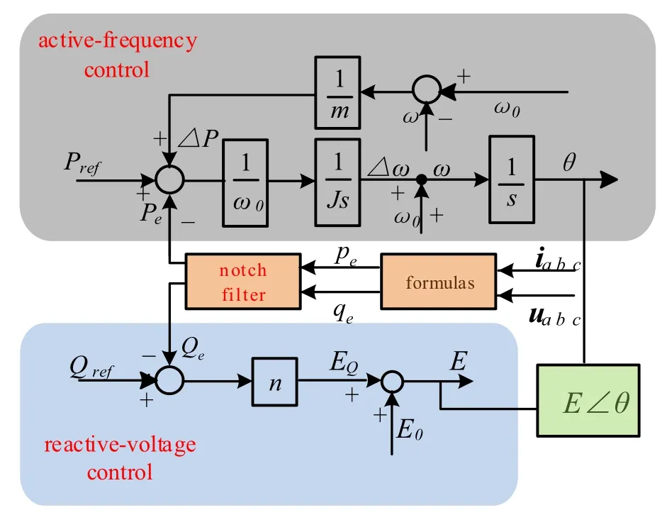
Fig.2 Control system block diagram of the VSG
2.1 Active power frequency control
The active power frequency control of a VSG is by emulating the rotor equation of the synchronous generator.The second-order equation of the traditional synchronous generator is used for modeling [23]:

wherePmandPeare the mechanical and average power of the synchronous generator, respectively.Jis the rotary inertia of the synchronous generator.Dpis the damping coefficient.ωandω0are the angular frequencies of the synchronous generator and grid, respectively.θis the rotation angle of the generator rotor relative to the a-phase stator winding.The virtual mechanical power of the VSG is calculated by:

wherePrefis the reference active power.ΔPis the output of the VSG frequency regulator.mis an active power adjustment factor which contains the damping coefficientDp.The instantaneous electromagnetic powerpeof the VSG is calculated by:

whereiα,iβare the grid currents in theαβcoordinate, anducα,ucβare the voltages at the filter bus in the αβ coordinate.The output average active power of the VSGPecan be obtained through a notch filter to reduce power fluctuation [12], as:

whereωmis the harmonic angular frequency of the notch filter andδis the quality factor.
It can be seen from the above formulas thatJemulates the moment of inertia.This can reduce system frequency fluctuation after disturbances.The frequency returns to the rated value by adjustingPmandPe.The difference between the VSG output angular frequencyωand the grid frequencyω0is used as feedback for the active power–frequency control to obtain the VSG output angular frequencyω, while the phase referenceθis obtained by integration ofω.
2.2 Reactive power voltage control
For the VSG reactive power voltage control, the control block diagram is shown in Fig.2, whereEis the reference voltage amplitude and consists of two parts:

whereE0is the no-load EMF of the VSG.EQis the output voltage of the reactive power regulator.nis the reactive power adjustment factor.Qrefis the reference reactive power, andQeis the output average reactive power of the VSG, obtained as:

The reference voltage amplitudeEand the angleθobtained by the active power frequency control are combined to derive the reference voltage for the inner-loop voltage predictive control.
3 Voltage model predictive control for VSG
3.1 Principle of voltage model predictive control
The 2-level 3-phase inverter shown in Fig.1 has 8 voltage vectors, as shown in Fig.3.From Fig.1, the dynamic vector equation can be expressed as:
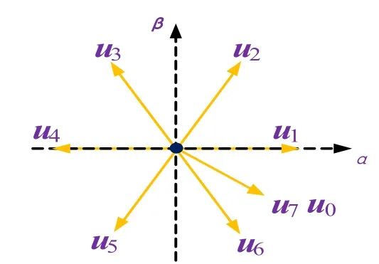
Fig.3 The output voltage vectors

whereLis the output filter inductance of the inverter, andCis the filter capacitor.R1andR2are the parasitic resistances of the filter inductor and filter capacitor, respectively.ifαβandiαβare the current vectors flowing through the filter inductorLand the grid-side inductorLgin the αβ coordinate, respectively.uis the output voltage vector of the inverter, anducαβis the voltage vector at the filter bus.Equation (7) can be discretized as:

whereTsis the sampling period.
Assuming thatiαβ(k) =iαβ(k+ 1), the prediction functions ofifαβanducαβcan be obtained as:

From (9), once the currentifαβ(k) and the capacitor voltageucαβ(k) at the current timetkare sampled, the inductor currentifαβ(k+ 1) at timetk+1can be predicted.Then, by sampling the grid currentiαβ(k), the voltageucαβ(k+ 1) at timetk+1can be further predicted.The cost function is constructed by sampling the reference voltage generated by the virtual synchronous control as:

The voltage vectors corresponding to the eight switching states are sequentially substituted into (10).By comparing the cost functions, the optimal switch state corresponding to the voltage vector that minimizes the cost function is selected and applied in the next control period.The VSG control block diagram based on voltage predictive control is shown in Fig.4.
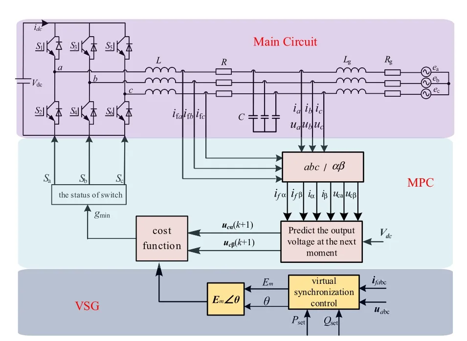
Fig.4 VSG control block diagram based on voltage model predictive control
3.2 Influence of parameter error on control performance
As the MPC strategy is a model-based control method,parameter changes can influence its control performance.Considering the temperature and current change during inverter operation, the actual values of the device parameters (filter inductance, filter capacitance, resistance, etc.)often deviate from their theoretical values.This deviation may affect the entire process of voltage predictive control.In the following, the effects of the parameter errors on the voltage predictive control are analyzed.
Assuming that the actual inductance isLand the modeled one isL0, the prediction function in (9) can be rewritten as (11) using the modeled inductanceL0.

Prediction errors, which are the difference between the predicted and actual values deduced based on (9) and(11), are depicted in (12).

In the same way, assuming that the actual capacitance isCwhile the modeled isC0, the influence of the capacitance error on voltage predictive control can also be analyzed as:

The analysis of (12) and (13) shows that when the parameter values in the prediction model equal the actual ones in the circuit, i.e.,L=L0andC=C0, the current and voltage prediction errors are zero.However, if the parameter values in the prediction model are inconsistent with the actual ones, there will be a voltage prediction error and the optimal switch function selected according to the traditional MPC algorithm will lose its optimality.Consequently, it cannot achieve error-free tracking of the reference values and affects the control performance of the system.
4 Voltage model predictive control with error compensation
4.1 Design of VMPC with error compensation
From the above analysis, it can be seen that when the parameters in the prediction model do not match the actual values, system control performance will deteriorate.In order to reduce the influence of the parameter errors on control performance and improve the voltage control accuracy, a new weighted predictive voltage control method is proposed in this paper.The proposed method uses the weighted sum of the sampled voltage and the predicted one to predict the voltage at the next period, as shown in Fig.5.
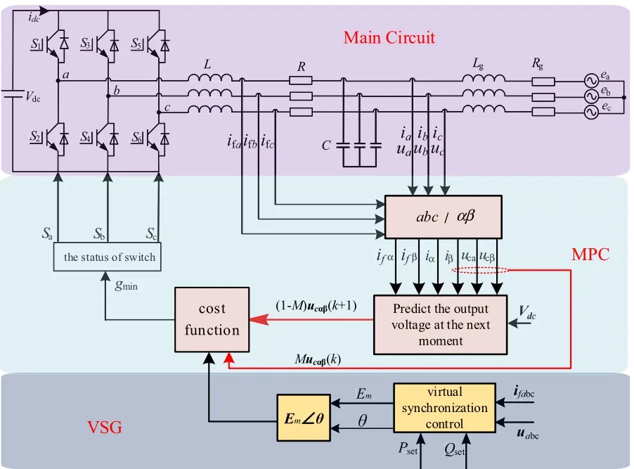
Fig.5 VSG control block diagram based on the proposed weighted predictive voltage control method
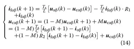
The prediction in (9) can be rewritten using the weighted sum of the sampled voltage and the predicted one considering the weighting factorM, to predict the voltage at the next period, as:
4.2 Effectiveness analysis of the proposed weighted VMPC method
The effectiveness of the proposed weighted voltage predictive control method in reducing the influence of parameter changes on the control error is analyzed in this subsection.When the inductance error exists, Eq.(11)can be rewritten as (15) based on (14), while (16) can be obtained from (15) and (9).
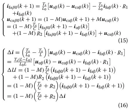
Comparing (16) with (12), ifM= 1, there is no voltage prediction, while if |1 −M|> 1, the impact of the inductance error will be further enlarged.However, with|1 −M|< 1, the voltage prediction error caused by the inductance error can be reduced.Therefore, choosing an appropriate value ofMcan weaken the influence of the inductance error on voltage tracking and improve voltage control precision.
Similarly, when a capacitance error exists, there are:

Comparing (18) with (13), the same conclusion can be obtained, which means that choosing anMthat meets|1-M|< 1 can enhance the parameter robustness of the proposed MPC strategy for VSG.
5 Experimental results
To verify the feasibility of the proposed VSG voltage MPC with error compensation, a hardware-in-the-loop experimental platform based on a Typhoon real-time simulator and PE-Expert4 as shown in Fig.6 is established and studies are conducted.In the experiments, the main circuit of the grid-connected inverter is run in the Typhoon real-time simulator, and the VSG-MPC control algorithm is implemented in the PE-Expert4 (Table 1).
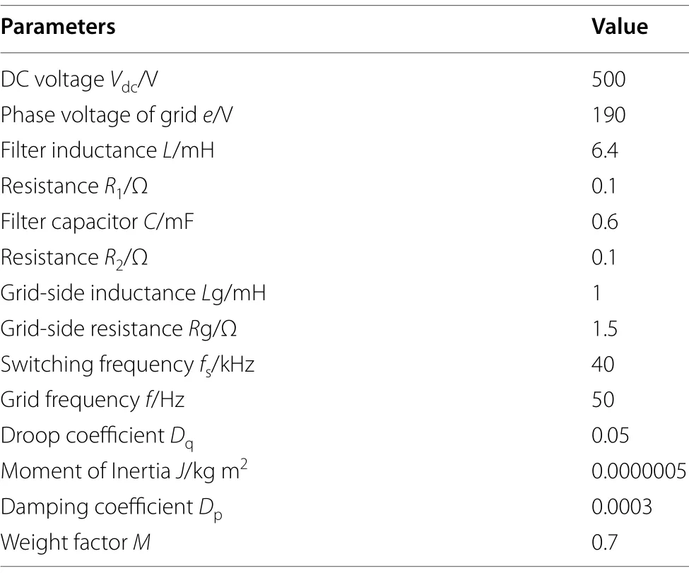
Table 1 Simulation parameters
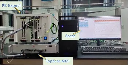
Fig.6 Typhoon and PE-Expert4 hardware-in-loop experimental platform
5.1 Comparison with accurate parameters
In order to verify the feasibility of the power outer loop control method with the compensation algorithm, the performance is compared with the traditional control methods without compensation.No parameter mismatch is considered here.
Figure 7 shows the results for the traditional power outer loop without compensation.The active powerPrefchanges from 500 to 2000 W in Fig.7a.As can be seen,the actual output active power of the inverter follows the reference change while the reactive power has a small disturbance at the corresponding moment due to the sudden change of the active power.Similar phenomena can be observed during the reactive powerQrefchange from 500 to 0 Var in Fig.7b.In both cases, the actual active and reactive power outputs by the inverter are stabilized at the given values after the transients.
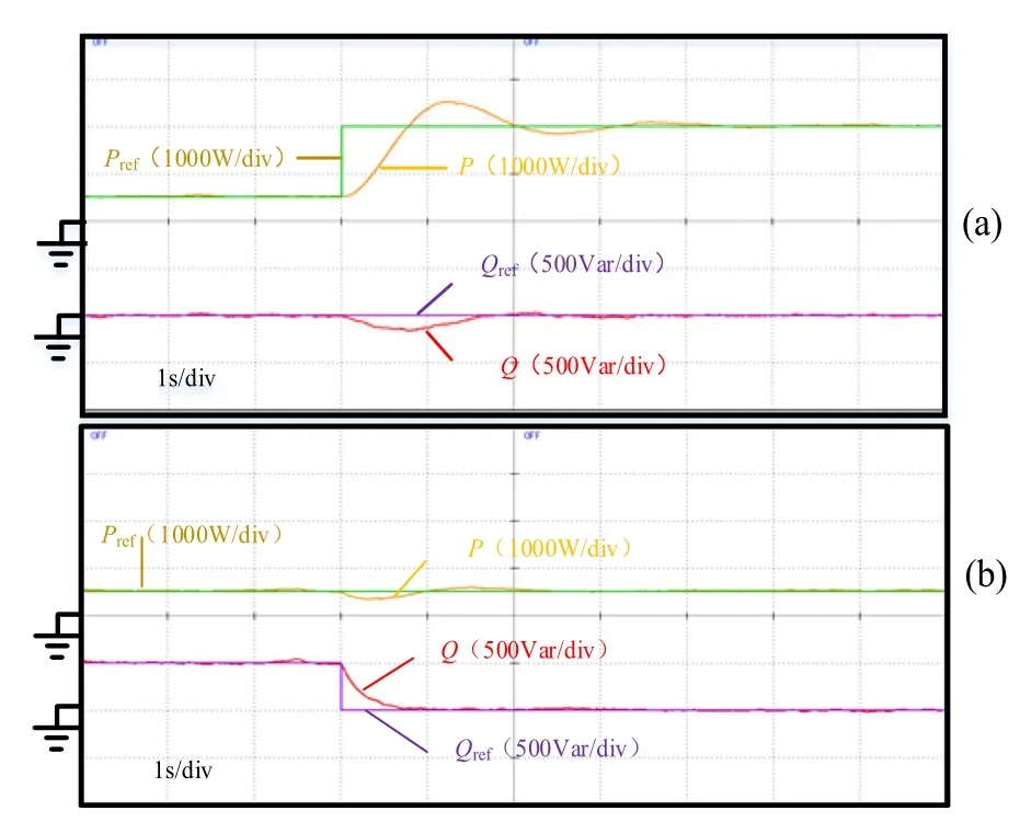
Fig.7 Experimental waveforms of the power outer loop without compensation.a Active power Pref changes from 500 to 2000 W.b Reactive power Qref changes from 500 to 0 Var
With the same active and reactive power changes,Fig.8a, b show the experimental results of the power outer loop with the proposed compensation.Comparing Figs.7 and 8, the results are almost the same, which means that the proposed weighted voltage predictive control method has the same control performance as the conventional method when the parameters are accurate.
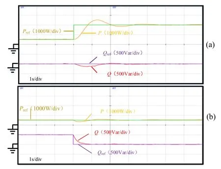
Fig.8 Experimental waveforms of the power outer loop with compensation.(a) Active power Pref changes from 500 to 2000 W.(b)Reactive power Qref changes from 500 to 0Var
Figures 9 and 10 further show the results during a sudden change of active power without and with error compensation, respectively.Figures 9a and 10a show the complete change process of the active power, while Figs.9b, c and 10b, c show the details of the β-axis voltage changes in different time ranges during the transients.As can be seen, for both cases, when the active power changes suddenly from 500 to 2000 W, the β-axis voltage values are increased.Comparing Figs.9 and 10, it can be seen that the waveforms corresponding to the two methods are almost identical.Both methods produce satisfactory voltage waveforms and the differences between the actual and the reference β-axis voltages for the two methods are almost identical in both dynamic and steady states.
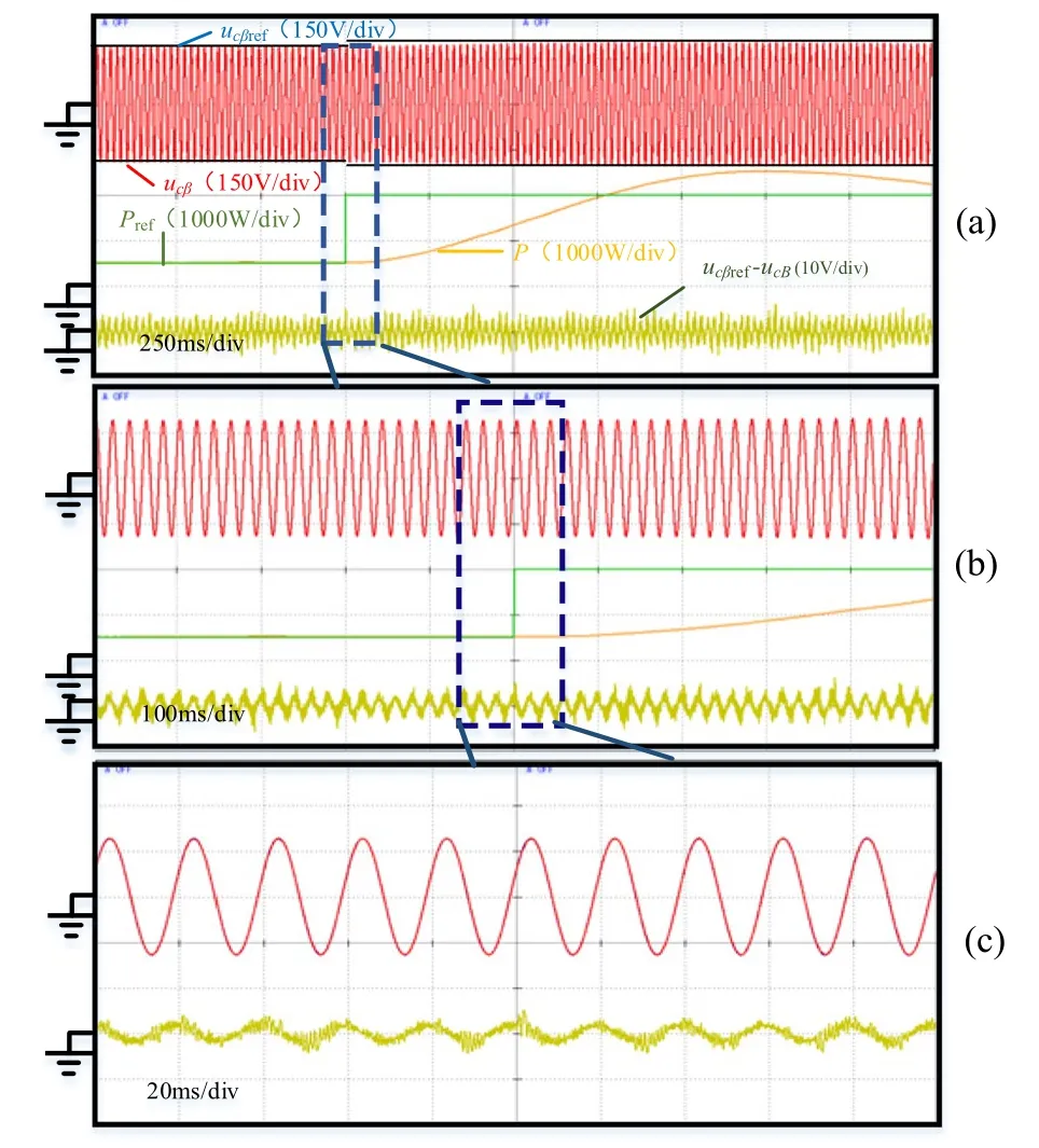
Fig.9 Experimental waveforms during sudden change of active power without error compensation.a 250 ms/div.b 100 ms/div.c 20 ms/div
Similarly, further experimental waveforms during reactive power change for the two methods are compared in Figs.11 and 12.As seen there, when the reactive power changes suddenly from 500 to 0 Var, the β-axis voltage values are reduced, while the waveforms corresponding to the two methods are almost identical.

Fig.10 Experimental waveforms during sudden change of active power with error compensation.a 250 ms/div.b 100 ms/div.c 20 ms/div
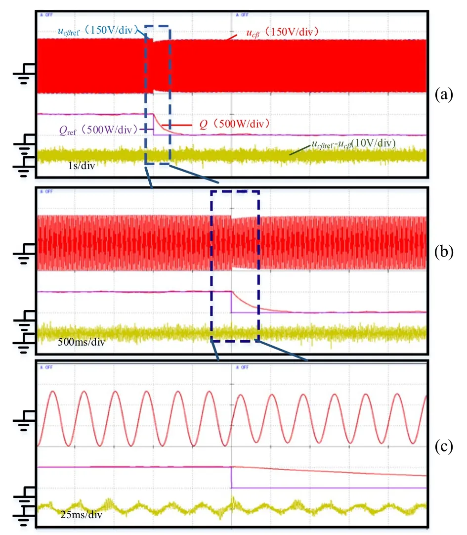
Fig.11 Experimental waveforms during sudden change of reactive power without error compensation.a 1 s/div.b 500 ms/div.c 25 ms/div
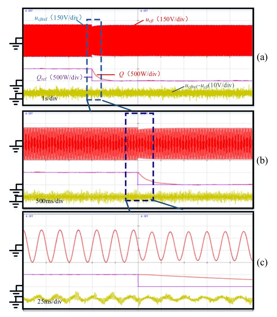
Fig.12 Experimental waveforms during sudden change of reactive power with error compensation.a 1 s/div.b 500 ms/div.c 25 ms/div
In summary, the power outer loop with the proposed compensation algorithm can achieve the same control effect as the conventional power outer loop without compensation.
5.2 Comparison with inaccurate parameters
To verify that the compensation strategy can reduce the influence of model errors on system control performance,the following experiments are carried out.The reference active powerPrefis set to 500 W, while the reference reactive powerQrefis 0 Var.
Figure 13a shows the results during the sudden change of parameters.The modeled inductance and capacitance become 1/3 of the actual values at timet1.As is shown,the difference between the actual and reference β-axis voltage values becomes larger after the changes of the inductance and capacitance values.Figure 13b shows a comparison of the two strategies with inaccurate parameters.M= 0 means there is no compensation for the voltage prediction value, whileM= 0.7 means there is an error compensation for the voltage prediction value.As can be seen, the difference between the actual and reference β-axis voltage values underM= 0.7 is much smaller than the one underM= 0.
Therefore, choosing an appropriate value ofMcan weaken the influence of the parameter error on voltage tracking, enhance the robustness in the face of parameter changes, and improve voltage control precision.
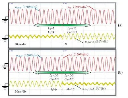
Fig.13 a Experimental results during sudden change of parameters.b Comparison of the two strategies
With the same inductance and capacitance errors,Figs.14 and 15 show the results during a sudden change of active power from 500 to 2000 W, without and with error compensation, respectively.Figures 14a and 15a show the complete change process during the sudden change of active power, while Figs.14b–d and 15b–d show the details of the β-axis voltage changes in different time ranges during the transients.

Fig.14 Experimental waveforms during sudden change of active power without error compensation.a 1 s/div.b 200 ms/div.c 20 ms/div.d 1 ms/div
Comparing the steady-state differences between the actual and reference β-axis voltage before and after the sudden active power change in Figs.14a and 15a, it can be seen that the compensation strategy can significantly reduce the voltage deviation and β-axis voltage error in steady state.In addition, by comparing Figs.14d and 15d,it becomes apparent that the compensation strategy can minimize the voltage error caused by parameter errors,and achieve better tracking of the reference voltage in the dynamic process.

Fig.15 Experimental waveforms during sudden change of active power with error compensation.a 1 s/div.b 200 ms/div.c 20 ms/div.d 1 ms/div
Similarly, Figs.16 and 17 are the experimental waveforms for the two control methods when the reactive power changes from 500 to 0 Var.Again, it can be seen that the compensation strategy can significantly reduce the voltage errors caused by parameter mismatch in both steady state and in transient during a reactive power step change.

Fig.16 Experimental waveforms during sudden change of reactive power without error compensation.a 1 s/div.b 200 ms/div.c 20 ms/div.d 1 ms/div
In summary, the proposed compensation strategy can reduce the influence of model errors on system control performance, enhance the robustness against parameter variation in both the steady state and dynamic process.
6 Conclusion
A new MPC method to control the output voltage of the VSG is proposed in this paper, one with enhanced robustness against parameter variation.The important conclusions can be summarized as follows:
(1) When the parameters are perfectly matched, the proposed control strategy with compensation is almost identical to the traditional control strategy in both static and dynamic process, and both have excellent control performance.
(2) When the parameters are not matched, the predicted voltage error of the conventional MPC method will increase significantly due to its sensitivity to parameter changes.
(3) In contrast, with parameter mismatch, the proposed weighted predictive capacitor voltage control method can reduce the influence of parameter changes and improve the parameter robustness both in the steady and dynamic state.
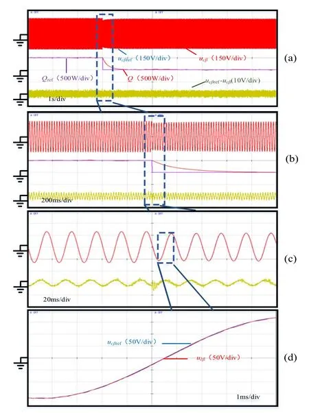
Fig.17 Experimental waveforms during sudden change of reactive power with error compensation.a 1 s/div.b 200 ms/div.c 20 ms/div.d 1 ms/div
Finally, the effectiveness of the proposed method is verified through theoretical analysis, and its feasibility and superiority are further demonstrated through control hardware-in-the-loop experimental tests.
Acknowledgements
Not applicable.
Authors’ contributions
LLG proposed the methodological framework and mathematical model, ZYX carried out theoretical analysis of the process and performed simulation and experiment to verify the proposed method.NJ, YYL and WW offered help in theory and practice, read and put forward suggestions for the paper.All authors read and approved the final manuscript.
Authors’ Information
Leilei Guo received the B.S.and the Ph.D.degree in electrical engineering from the School of Electrical Engineering and Automation, Hefei University of Technology, Hefei, China, in 2010 and 2016, respectively.His current research interests include model predictive control of induction motors, permanent magnet synchronous motors, and power converters.
Zhiye Xu is a graduate student in Zhengzhou University of Light Industry.His current research interests include model predictive control method for power converter, grid impedance identification.
Nan Jin received B.S.and M.S.degree in electrical engineering from Zhengzhou University of Light Industry, Zhengzhou, China, in 2003 and 2007,respectively, and Ph.D.degree in power electronics and electrical drives from Shanghai Jiao Tong University, Shanghai, China, in 2012.He is a professor at Zhengzhou University of Light Industry, Zhengzhou, China.His research interests include model predictive control method for power converter, fault diagnosis and tolerant control of power electronics system, wireless power transfer.Dr.Jin was the recipient of the 2018 Highlighted Paper Award from IEEE TPEL.
Yanyan Li received the Ph.D.degree in control science and engineering from the college of artificial intelligence, Tianjin key laboratory of intelligent robotics, Nankai University, Tianjin, China, in 2017.She is currently a Lecturer with Zhengzhou University of Light Industry, Zhengzhou, China.Her current research interests include model predictive control for power converters, grid impedance identification, and tolerant control of power electronics systems.
Wei Wang is Major in flexible electronic materials, artificial intelligence and new energy devices.He received his Ph.D in microelectronics from Concordia University, Canada.In 2017, he joined Zhengzhou University of Light Industry,engaged in the research of artificial intelligence, tactile perception, intelligent sensor design and computer vision, and committed to the industrialization of artificial intelligence, intelligent sensor and other technologies.
Funding
This work was supported in part by the National Natural Science Foundation of China (51707176), in part by the Youth Talent Support Project of Henan Province (2019HYTP021), in part by the Youth Talent Support Project of Henan Province (2019HYTP021), in part by the Key Research, Development and Promotion Special Project (Science and Technology) of Henan Province(202102210103).
Availability of data and materials
Not applicable.
Declaration
Competing interests
The authors declare that they have no known competing financial interests or personal relationships that could have appeared to influence the work reported in this paper.
杂志排行
Protection and Control of Modern Power Systems的其它文章
- A comprehensive review of DC fault protection methods in HVDC transmission systems
- Application of a simplified Grey Wolf optimization technique for adaptive fuzzy PID controller design for frequency regulation of a distributed power generation system
- A critical review of the integration of renewable energy sources with various technologies
- Operational optimization of a building-level integrated energy system considering additional potential benefits of energy storage
- An integrated multi-energy flow calculation method for electricity-gas-thermal integrated energy systems
- Sliding mode controller design for frequency regulation in an interconnected power system
