Superconducting energy storage technology-based synthetic inertia system control to enhance frequency dynamic performance in microgrids with high renewable penetration
2021-08-24GaberMagdyAbualkasimBakeerandMohammedAlhasheem
Gaber Magdy, Abualkasim Bakeer and Mohammed Alhasheem
Abstract With high penetration of renewable energy sources (RESs) in modern power systems, system frequency becomes more prone to fluctuation as RESs do not naturally have inertial properties.A conventional energy storage system(ESS) based on a battery has been used to tackle the shortage in system inertia but has low and short-term power support during the disturbance.To address the issues, this paper proposes a new synthetic inertia control (SIC) design with a superconducting magnetic energy storage (SMES) system to mimic the necessary inertia power and damping properties in a short time and thereby regulate the microgrid (µG) frequency during disturbances.In addition, system frequency deviation is reduced by employing the proportional-integral (PI) controller with the proposed SIC system.The efficacy of the proposed SIC system is validated by comparison with the conventional ESS and SMES systems without using the PI controller, under various load/renewable perturbations, nonlinearities, and uncertainties.The simulation results highlight that the proposed system with SMES can efficiently manage several disturbances and high system uncertainty compared to the conventional ESS and SMES systems, without using the PI controller.
Keywords: Synthetic inertia control (SIC), Load frequency control (LFC), Superconducting magnetic energy storage(SMES), Renewable energy sources (RESs), Microgrid (µG)
1 Introduction
There has recently been a great trend to incorporate renewable energy sources (RESs) into the power grid as a potential option for reducing carbon dioxide emissions, while the microgrid (μG) concept provides a promising remedy to the key obstacles of incorporating more renewables into power networks.μG is a small power grid comprising distributed generators (DGs),energy storage systems (ESSs), micro-turbines, and several customers [1].These DGs are classified as nondispatchable sources (e.g., solar and wind energy) as well as dispatchable sources (e.g., micro-turbine, gas turbine, and small hydraulic power plants).Consequently,DGs replace the synchronous generators that have been considered the key source of dynamics in conventional power systems.Compared to traditional power systems with synchronous generators, µGs with RESs/DGs have either small or no inertia, as most RESs do not have a spinning mass that provides the power system with the inertial property, and thus their related inertia factors are approximately equal to nil [2].Therefore, with the large penetration of renewables in µGs, the system dynamic performance and stability deteriorate as the result of the reduced system inertia and damping factors.Also, the irregular nature of RESs can cause frequency and voltage instability of the power system.This is likely to restrict the high penetration of RESs [2].Hence, μGs are more susceptible to disturbances such as significant frequency variations, unexpected load variations, involuntary islanding events, and short-circuit faults when compared to traditional power systems.
Large penetration of RESs in µGs can cause large system frequency deviation, and thus the load frequency control (LFC) may fail to keep the system frequency at the nominal value.To cope with these barriers, one of the notable key technologies that can be implemented in inverter-based RESs assisted by ESS is to emulate inertia using efficient inertia control methods.This strategy is generally known as synthetic inertia control (SIC) that simulates actual synchronous generators’ behavior without using a spinning mass to increase the inertia of the system [3].
Substantial attempts have been devoted to implementing suitable control strategies for emulating synthetic inertia in μGs and support frequency stability to ensure reliable performance against system uncertainty [4–10].A classical control method based on a proportional-integral (PI) controller is proposed to provide SIC for frequency stability improvement of µG with high-share of RESs in [4].SIC based on model predictive control (MPC)strategy is proposed for frequency stability improvement considering high RESs penetration [5].Reference[6] applies a robust control method based on the coefficient diagram method (CDM) to provide SIC for a lowinertia µG, whereas a robust SIC based on the optimal CDM controller is presented for frequency stabilization of a two-area interconnected µG considering RESs and electric vehicles (EVs) [7].In addition, a robust control method based on the H-infinite technique is proposed to provide SIC for enhancing the frequency stability of an islanded µG [8].A fuzzy logic-based SIC is proposed in[9] to provide frequency regulation in a power system,while an adaptive SIC based on a chicken swarm optimizer is used to enhance the frequency dynamic performance of a power system considering RESs [10].
Although the above-mentioned approaches can successfully address system frequency deviation caused by large-scale RESs penetration, they cannot give adequate synthetic damping and thus their performance may be inadequate in low-damping µGs.An enhanced SIC system design to simulate inertia and damping properties for low-inertia µG frequency stabilization is presented in[11].A virtual synchronous generator (VSG) concept that emulates a real synchronous generator’s behavior (i.e.,inertia and damping properties) based on EV batteries is implemented to support the frequency stability of lowinertia modern power grids [12].
On the other hand, in most studies on the frequency stability issues based on the SIC technique, the proposed designs are based on conventional ESS (e.g., battery).Therefore, because of the low and short-term capacity of conventional ESS, they are unable to provide adequate inertia power, and consequently, this may lead to system instability.These limitations can be avoided by applying the superconducting magnetic energy storage(SMES) technology because of its outstanding properties such as quick response, high efficiency (over 95%), long life, and repetitive charging/discharging cycles [13].In addition, the expected cost of the SMES unit is likely to fall to 25 percent of the current cost with technological development and the discovery of new superconductive materials [14].In a power plant in Kameyama, Japan, a 10 MVA SMES unit is coupled with a traditional wind farm to alleviate the impact of power fluctuation [15].For the regular load-leveling cycle in 2030–2040, the installation of a large-scale 1 GWh SMES conversion system is planned [16].
Some recent research and studies on the SMES system have been conducted to enhance frequency stability in µGs in [17–21].An implementation of SMES system-based fuzzy logic control is applied to improve the stability and reliability of an islanded µG [17], and an SMES-based MPC technique is applied for the LFC of a standalone hybrid power system in [18].LFC analysis of a µG composed of photovoltaic (PV), wind energy, and SMES system is presented in [19], whereas a hybrid ESS based on SMES and battery is applied to improve the frequency stability of an islanded µG [20].A hybrid adaptive fuzzy sliding mode control-based SMES system is presented to improve the performance of a two-area interconnected power system [21].Hence, implementing the SIC system based on SMES can provide a large amount of power in a short period to mitigate the unbalanced sharing of power and frequency deviation, and accordingly, improved stability and balanced status of µGs can be accomplished.
Taking account of the investigations described above,this study contributes to the subsequent points.We:
1.Present an effective SIC system to emulate the inertia and damping properties of a real synchronous generator, thus improving the frequency dynamic performance of µGs with high renewable penetration for several contingencies.
2.Propose an SMES (i.e., rapid-responding ESS)-based SIC system to improve the frequency stability of µGs considering the large scale of RESs penetration, nonlinearities, and uncertainties.In comparison, the SIC designs in the literature rely on the conventional battery-based ESS, which cannot provide enough inertia power within a short time and thus leads in certain cases to µG instability.
3.Use a PI controller with the proposed SIC system to emulate the primary and secondary frequency control loops in conventional generators and reduce system frequency deviation.The gains of the PI controller are optimally selected by the whale optimization algorithm (WOA) to minimize the variance in system frequency.
4.Consider, in the design of the proposed SIC system, system nonlinearities, e.g., governor dead-band(GDB), generation rate constraint (GRC), and RESs/loads uncertainties, so the simulated system is close to the real μG.
5.Compare the proposed SMES-based SIC system with the PI controller, referred to as controlled SMES(CSMES), with both an SMES-based SIC system without the PI controller, referred to as uncontrolled SMES (UCSMES), and the conventional ESS-based SIC system without the PI controller [11], referred to as conventional ESS, under various load/renewables perturbations, nonlinearities, and uncertainties to highlight the superiority of the proposed system.
The rest of the paper is arranged as follows.Section 2 describes the configuration and modeling of the studied islanded µG considering renewables (i.e., solar and wind energy).The state-space model of the considered µG is given in Sect.3 and the proposed SMES-based SIC system is presented in Sect.4.Section 5 describes the PI controller design using WOA, and Sect.6 provides the simulation results and discussion of different scenarios.The paper is concluded in Sect.7.
2 System configuration and modelling
2.1 Dynamic model of an islanded µG
An islanded µG is considered as the test system for designing and validating the proposed SMES-based SIC system.Figure 1 displays the simplified islanded µG model with the proposed SIC system based on SMES technology.The islanded µG consists of a reheat power plant rated at 15 MW, a load with peak power of 15 MW including industrial loads with peak power of 10 MW and residential loads with peak power of 5 MW, solar power rated at 7.5 MW, wind power rated at 8.5 MW, and 4.5 MW ESS.The base power of the system is 15 MW.The dynamic configuration of the islanded µG with the proposed control system is displayed in Fig.2, while the dynamic parameter values are provided in Table 1.Further details on the system data can be found in [11].

Table 2 Nominal wind turbine parameters
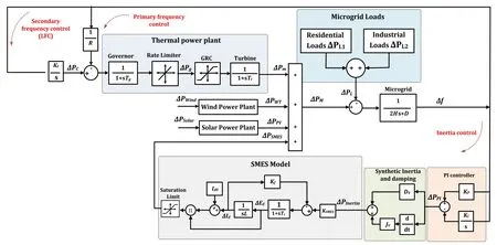
Fig.2 Frequency response model of the islanded µG with the proposed SIC system

Table 1 Dynamic parameters of the studied islanded µG
The physical constraints such as GDB of the governor and GRC of the turbine unit need to be considered to achieve an accurate representation of the μG non-linearity [22].In this paper, the GRC of a thermal power plant is reported at 12% pu/min and the GDB is determined as 0.06% (0.030 Hz).
2.2 Mathematical model of the wind power
To provide an accurate model of wind power generation,the real wind speed is multiplied by the stochastic speed fluctuations that can be constructed by white noise as shown in Fig.3.The wind output power can be formulated as [2]:

Fig.3 The wind power model for LFC analysis using MATLAB/Simulink [2]

whereVWrepresents the rated wind speed (m/s),ATreflects the rotor area swept (m2),ρdenotes the air density (Kg/m3), andCPis the rotor blade power coefficient.Also,CPcan be described in detail from turbine coefficientsC1toC7as [2]:

whereβis the pitch angle,λIrepresents the intermittent tip-speed ratio, andλTis the optimal tip-speed ratio(TSR) and can be estimated by:

whererTis the rotor radius.
Variable-speed wind turbines operate at optimal tipspeed ratio throughout all wind speed situations.The intermittentλIcan be determined as:

In this study, the islanded μG is investigated with a wind farm incorporating seven identical wind turbines.The parameters for each turbine are listed in Table 2.

Table 3 Dynamic parameters of the SMES control loop
2.3 Mathematical model of the PV system
Solar irradiation power can be defined by an identical PV system that consists of several cells with a rating equal to the quantity of the units produced by the independent PVs.As the PV generation system’s output power is affected by environmental conditions, the power variations from the solar PV generation system can be determined by taking into account the variance of the nonuniform and uniform insolation as displayed in Fig.4.To have a reliable model of the PV system for the frequency stability analysis of µGs, the stochastic output fluctuations that can be constructed by the white noise are amplified by the standardized deviation [2, 23].The PV power variance is modeled to behave similarly to the real solar power change as:

Fig.4 The PV solar power model for LFC analysis [2]

Therefore, the islanded µG is investigated with a wind farm (i.e., high wind power fluctuations) rated at 5.25 MW and a solar farm (i.e., low solar power fluctuation) rated at 2.25 MW.
3 State‑space dynamic model
The deviation of the studied system frequencyΔftaking into account the frequency control loops of the primary,secondary, and inertia control units can be given as:

where
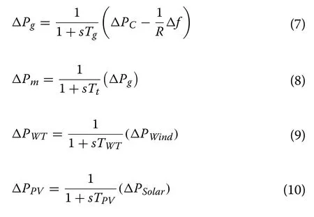
Using the dynamic model of the µG as shown in Fig.2 and (6)–(10), its state-space equations can be expressed as [4]:

whereXrepresents the state vector,Yis the output,Uis the control input signal, andWrefers to the input disturbance vector.A,B,C,D,E, andFmatrices correspond to state variable, input of control signal, LFC signal, zero vector with the same scale as the input control signal,disturbance input, and zero vector with the same scale as the input disturbance vector, respectively.The detailed state-space model of the islanded µG is given as:

4 Design of proposed SMES‑based SIC system
The proposed SIC system is designed to imitate the inertia power and damping property in µGs to enhance the frequency stability of low system inertia and damping when μGs are strongly penetrated by RESs.Figure 5a shows the dynamic model of the proposed SIC system based on ESS (either conventional ESS or an SMES system).The synthetic inertia part is based on derivative control, and calculates the rate of change of frequency(RoCoF) to improve the active power and contribute to the µG set-point during large-scale RESs penetration and uncertainties [11].For a short settling time, the synthetic damping part is developed dependent upon the system frequency deviation [11].Accordingly, the synthetic damping property and synthetic inertia power can be adequately emulated in µGs, improving the frequency stability of low system inertia and damping at large-scale RESs penetration.The dynamic equation for emulating inertia and damping properties (PInertia) in µG is given as:

where DVis the synthetic damping and JVrepresents the synthetic inertia.
The conventional ESS-based inverter is presented in Fig.5b, and the dynamic equation of the proposed SIC system using conventional ESS (PESS−Inertia) can be obtained as:

Fig.5 Dynamic models: a SIC system based on ESS and b conventional ESS-based inverter

where TESSis the time constant of the conventional ESS.
Owing to the features of SMES such as fast response,high efficiency, and repetitive charging/discharging cycles [13], a new SIC design that relies on SMES technology is introduced to enhance the frequency stability ofµGs considering high renewables penetration as shown in Fig.2.
The key component in the SMES system is the magnetic coil that is made from a specific superconducting material with almost zero resistance [24].The nil-energy loss in the magnetic coil of the SMES system is assured providing the SMES coil is maintained in the superconducting condition thus achieving high efficiency.The SMES coil is cooled by immersion in the helium vessel at a superconducting temperature.The stored energy in the magnetic coil of the SMES (ESMES) varies with the magnetic coil size (L) and the current of the coil (ISMES) as:

The SMES coil is connected to the point of common connection (PCC) of the power system through a 12-pulse thyristor bridge and a transformer [21].The main configuration of the SMES conversion system is displayed in Fig.6.The role of the transformer is to adjust the voltage applied to the thyristor bridges in the SMES system [24].The bypass thyristors are turned off during discharging and charging modes, whereas the SMES coil acts in the freewheeling state (i.e., neither charging nor discharging) when the two bypass thyristors are turned on simultaneously.The SMES coil must have a closed loop to ensure a continuously circulating coil current to avoid harm to the power devices.

Fig.6 The schematic diagram of the SMES unit
The current of the SMES coil ( Id) is unidirectional.When the voltage across the SMES coil is positive, the SMES coil starts to charge and store energy.On the other side, the SMES coil discharges once a negative voltage is applied to the coil terminal.The firing angle (α) of the 12-pulse bridge is controlled to manage the SMES coil charging/discharging process.The relationship between the firing angle (α) and the voltage applied to the SMES coil ( Ed) can be expressed as:

where Vd0is the maximum DC voltage that can be generated by a 6-pulse bridge (in kV), Idis the current of the SMES coil (in kA), and the damping resistance is defined by RD(in Ω).
According to (18), when the firing angle (α) is less than 90°, the voltage level of the SMES is positive, and thus the SMES coil begins to charge.In contrast, when the firing angle (α) is greater than 90°, the voltage level of the SMES coil is negative, and the SMES coil discharges [24].
In this study, the SMES device is used to absorb/supply electrical power from/to the power system with a rapid response considering the maximum/minimum capacity limits of the SMES unit.The full block diagram of the SMES system is incorporated with the islanded µG as shown in Fig.2.The voltage applied to the SMES coil( Ed) is continuously regulated by the SMES input signal(PInertia).The variance of the SMES coil current (Id)is used as a negative feedback signal (Kf) to be added to the SMES input signal [21].As shown in Fig.2, the voltage deviation across the SMES coil (∆Ed) and the current deviation (∆Id) can be described as:


whereTcis the time constant of the converter, andKSMESis the SMES control gain.
The total coil current of the SMES is (Id+Id0) where Id0is the initial coil current.Thus, the total power deviation of the SMES can be given as:

The parameters of the SMES unit are listed in Table 3.This study shows that the SMES can provide good system performance during transients even though the inertia of the system is reduced to 30% of its nominal value.

Table 4 Multiple disturbances in load demand
5 Design of virtual controller based on whale optimization algorithm (WOA)
In traditional power systems, the frequency control loops can be categorized into primary and secondary controls.In addition, the synchronous generator uses the turbine governor as the primary control to regulate the system frequency [22].Droop control is usually used to maintain the system frequency at the permissible range by regulating the turbine power.LFC is used to sustain the frequency of the system at its nominal value (i.e., 50 or 60 Hz) for a time variation of a few minutes after system interruption [3].Therefore, comparable conventional frequency control loops can be designed and emulated for the proposed synthetic inertia-damping control system.The proportional controller represents the primary controller, while the integral controller indicates the secondary controller of the power grid.The virtual(PI) controller for the SIC system is developed to function independently of other controllers (i.e., conventional frequency control loops).Thus, the stored energy in the SMES unit is used to enhance the frequency stability ofµG in terms of steady-state and transient performance.The transfer function of the PI controller in Fig.2 can be expressed as:

where KPrefers to the proportional gain and KIrefers to the integral gain.
In this study, the WOA proposed in 2016 [25] is applied to tune the PI controller parameters of the proposed SIC system based on SMES technology.The integral of squared error (ISE) is used as an objective function for the targeted WOA and can be expressed as [2]:

wheretsimis the simulation time.
The gain constraints of the PI controller are:

WOA is a new search algorithm, which essentially uses the concept of whales’ social behavior.Compared to other swarm algorithms, WOA has a high convergence speed and a small number of parameters to be configured[25].Also, it has recently been effectively applied to various engineering problems for design optimization [25,26].
Among different whale types, humpback whales are the largest and hunt krill and small fish.The hunting practice of humpback whales relies on the methodology of bubble-net feeding.Thus, the twisting bubble-net fattening plan is numerically illustrated in WOA.The WOA mathematical model identifies actions of surrounding prey,setting up the maneuver of spiral bubbles, and searching for the prey.It is possible to model it as described below.
5.1 Encircling prey
The best attribute related to all whales is that they can identify and then surround the area of the prey.The position of the prey is considered as a candidate solution.Since the initial prey position is previously unknown, the WOA algorithm finds the current optimal solution close to the most feasible solution.The other search agents alter their position towards the position of the present best search agent in the wake of having the present best position [25].The rounding of the humpback whales to the prey can be formulated as:

wheredrefers to the distance of theithwhale to the prey, x∗(t) is the vector of prey position, t is the iteration number, x(t) indicates the vector of the whale position,and a and c are coefficient vectors that can be given as:

where q describes a linear decrease from 2 to 0 for the continuous iterations and r is a random vector within the range of (0, 1).
5.2 Mechanism of bubble‑net attacking
To mathematically model the behavior of the bubble-net of humpback whales, two approaches are used as follows[25, 26]:
(a) Shrinking encircling mechanism.In this method,the whales swim in shrinking circles around the prey, which can be accomplished by reducing the value of the vector q in (27) from 2 to 0.Thus, the fluctuation range ofais also reduced to 0 ≤a≤ 1.
(b) Spiral updating position.In a spiral shape manoeuvre, the humpback whales swim around the prey,and the whales’ position can be changed as [25]:

wherebis a standard that estimates the logarithmic spiral shape andlis a random number in the range of (− 1, 1).
Humpback whales swim up inside a shrinking circle around the prey and simultaneously along a spiralshaped direction.In order to model these concurrent actions, it is presumed that there is a 50% chance of choosing between either the spiral model or the shrinking encircling mechanism to change the position of the whales during optimization.The mathematical model can be defined as [25]:

where p is a random number in the range of (0, 1).
5.3 Search for prey
The humpback whales are looking for prey in this phase and this introduces the WOA or global search exploration.It is noted thata> 1 can describe the process of searching.The whales’ position can be updated as [25,26]:

where xran(t) is the vector of a random whale position extracted from the present population.
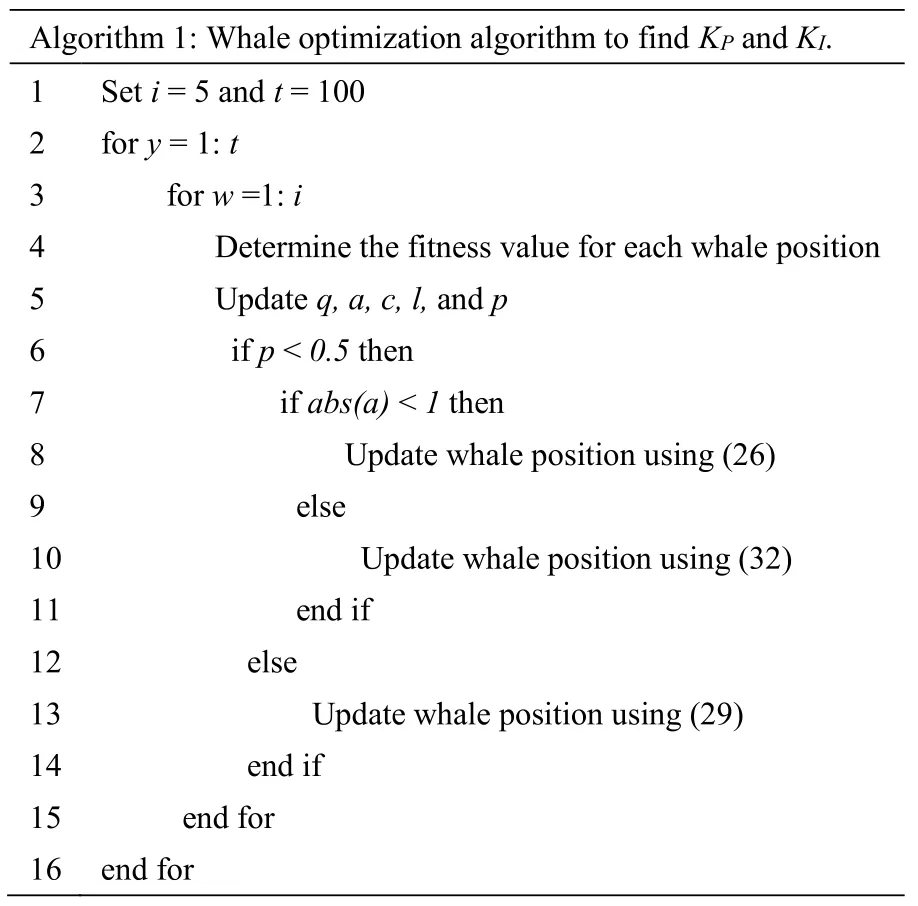
The main aim of WOA in this paper is to mitigate the variance in the system frequency by determining the optimal parameters of the PI controller for the proposed SIC system.The WOA programming is done using MATLAB, and the WOA procedure to adjust the PI controller gains (i.e.,KPandKI) is defined in Algorithm 1.The WOA’s optimum characteristics consist of 5 whales and 100 iterations.After running WOA, the optimal proportional and integral gains are determined as 0.002 and 2.000, respectively.These parameters will provide the appropriate control to the proposed SIC system to absorb or supply electrical power from/to the µG as needed with fast response and small steady-state error.
6 Simulation results and discussion
To verify the efficacy of the proposed SMES-based SIC system with the PI controller (i.e., CSMES) under various load/RESs perturbations, simulations of the μG are carried out using MATLAB/Simulink®software.The studied islanded µG contains a thermal power plant, solar power,wind power, ESS/SMES, and load demand as shown in Fig.2.The effectiveness of the proposed CSMES system in low system inertia and damping is evaluated by comparing its reliability with that of an SMES-based SIC without using the PI controller (i.e., UCSMES) and conventional ESS-based SIC system without using the PI controller (i.e., conventional ESS) in [11].In this analysis,system nonlinearities (e.g., GRC and GDB) and the RESs/loads uncertainties are also considered.
The µG with the proposed control scheme is tested and evaluated under a realistic load pattern with a short term of 20 min as shown in Fig.7.The combination of both load step change that represents the forced outage of generation unit or sudden load switch off, and ramp load change that represents industrial load, produces a random change in the load.This represents a realistic load pattern, which is considered as a combination of high random load changes (i.e., industrial load), and low random load changes (i.e., residential load).These load profiles are applied for both studied scenarios (A and B) and summarized in Table 4.

Fig.7 Load profiles: a industrial and b residential
?
6.1 Scenario A: System performance evaluation without RESs penetration
In this scenario, the targeted islanded µG with the proposed CSMES system is tested in conditions of 100%(high), 50% (medium), and 30% (low) of the nominal system inertia, and Figs.8, 9, and 10 show the respective frequency responses.The residential and industrial loads shown in Fig.7 are implemented at the operating conditions given in Table 4.
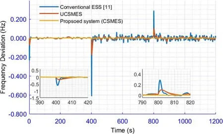
Fig.8 Frequency deviation of the considered system for scenario A at 100% system inertia

Fig.9 Frequency deviation of the considered system for scenario A at 50% system inertia

Fig.10 Frequency deviation of the considered system for scenario A at 30% system inertia
For the considered system with a nominal parameter(high-inertia system), the µG with the proposed CSMES is more reliable and faster than the conventional ESS and UCSMES systems without the PI controller.During the connection of the industrial load at 400 s, the frequency deviation of the µG with the CSMES is 0.0002 Hz,while with the UCSMES and conventional ESS, they are 0.20 Hz and 0.60 Hz, respectively.Furthermore, the performance of the proposed CSMES (with∆f≈ 0 Hz) is superior to the UCSMES (∆f= 0.1 Hz) and conventional ESS (∆f= 0.3 Hz) systems when disconnecting the industrial load at 800 s.
In the cases with 50% or 30% system inertia, the lack of system inertia has a major effect on system stability with the UCSMES and conventional ESS systems, as shown in Figs.9 and 10, respectively.As shown, the proposed CSMES system greatly enhances system frequency and leads to small system transients in comparison with the UCSMES and conventional ESS systems.When the industrial load is connected at 400 s, the frequency deviation of the µG with the CSMES is 0.0003 Hz and 0.0005 Hz in the case of medium and low system inertia,respectively.In contrast, the system with the UCSMES and conventional ESS has respective frequency changes of 0.20 Hz and 0.85 Hz in cases of 50% system inertia,and 0.25 Hz and 1.00 Hz in cases of 30% system inertia.From the results, it is clear that the frequency deviation of the conventional ESS system does not meet the standard permissible frequency change, and this reduces the dynamic security of the µG.
6.2 Scenario B: System performance evaluation with RESs penetration
In this scenario, the efficiency of the µG with the proposed CSMES is examined and assessed by applying highly-oscillated wind power and low-oscillated solar power as shown in Fig.11, and high-random load variation and low-random load variation displayed in Fig.7.In addition, the system with the proposed CSMES system is examined in conditions of high, medium, and low system inertia to reflect the important impact of μG actual operation.High level penetration of RESs further reduces the current inertia value.Therefore, this case is performed under the presumed different operating conditions of industrial and residential loads and RESs in Tables 4 and 5, respectively.Figures 12, 13, and 14 show the frequency deviations of the considered system with RESs at 100%, 50%, and 30% system inertia, respectively.It is clear that the system does not have a notable deviation in the frequency before 400 s as most of the high fluctuated disturbances (industrial load and wind energy) happen after 400 s.

Fig.1 A simplified scheme of the islanded µG with the proposed SMES-based SIC system
As displayed in Fig.12, in the case of 100% system inertia, the proposed CSMES system greatly enhances the performance of the system frequency and provides a small system transient magnitude in comparison with the UCSMES and conventional ESS systems.For example,the frequency deviations of the µG with the conventional ESS and UCSMES systems are 0.62 Hz and 0.22 Hz,respectively, during the wind farm connection at 600 s, in contrast to 0.0001 Hz with the proposed CSMES.

Fig.12 Frequency deviation of the considered system for scenario 2 at 100% of system inertia
As the inertia is decreased to 50% and 30%, the frequency deviations of the μG with the conventional ESS system oscillates significantly as displayed in Figs.13 and 14, respectively.With the proposed CSMES, the system is more reliable and faster than the UCSMES under these conditions.When the wind farm is disconnected at 600 s, the UCSMES and conventional ESS systems lead to respective frequency changes of 0.17 Hz and 0.78 Hz in cases of medium system inertia, and 0.18 Hz and 0.95 Hz in cases of low system inertia.The CSMES yields a very small frequency variation in the case of 50% and 30% system inertia through all simulation time.From the results,it is clear that the frequency deviation with the conventional ESS system represented in [11] does not meet thestandard permissible frequency changes.In addition,the proposed controller has approximately zero frequency deviation compared to the other systems before the disturbance at 400 s.Thus, the best performance in frequency is achieved by using the proposed CSMES system in the circumstances of 100%, 50%, and 30% system inertia.
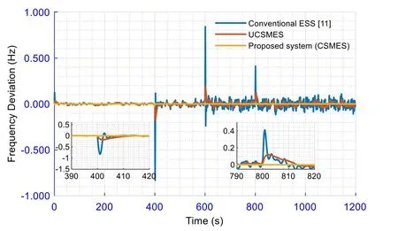
Fig.13 Frequency deviation of the considered system for scenario B at 50% of system inertia

Fig.14 Frequency deviation of the considered system for scenario B at 30% of system inertia
7 Conclusion
This study presents a new SIC system design to emulate both the inertia power and damping property of the µG, to enhance the frequency stability of µGs with high renewable penetration for various contingencies.A SMES-based SIC system is proposed to mimic the necessary inertia power in a short time and regulate the frequency of the system during different perturbations.SIC design in the literature is based on conventional ESS, which cannot provide enough inertia power for a short time and in certain cases leads to μG instability.This study proposes the use of a PI controller, referred to as the virtual controller, to mimic a power system’s traditional frequency control loops.The proposed controlled-SMES (CSMES) system is applied to improve the frequency stability of the system considering large-scale RESs penetration, RESs/load uncertainties, and system nonlinearities.The efficiency superiority of the proposed CSMES system is validated by contrasting it with the UCSMES and conventional ESS systems.The simulation results demonstrate that the proposed system can significantly promote µG high renewable penetration for a variety of contingencies.
Abbreviations
SIC: Synthetic inertia control; LFC: Load frequency control; ESS: Energy storage system; SMES: Superconducting magnetic energy storage; CSMES: Controlled SMES system; USMES: Uncontrolled SMES system; RESs: Renewable energy sources; PV: Photovoltaic; µG: Microgrid; GRC: Generation rate constraint;GDB: Governor dead-band; PI: Proportional-integral; RoCoF: Rate of change of frequency; ∆f: System frequency deviation, (Hz);R: Speed regulation of μG,(Hz/pu MW);Tt: Turbine time constant, (s);Tg: Governor time constant, (s);H: Microgrid inertia constant, (pu MW s);D: Microgrid damping coefficient,(pu MW/Hz);Ki: Integral control gain;∆PL: Load variation, (MW pu);f: System frequency, (Hz); ∆PPV: PV power change, (pu); ∆PWT: Wind power change, (pu);∆PSMES: SMES power change, (pu);PWT: Wind turbine output power, (W);ρ: Air density, (Kg/m3);VW: Rated wind speed, (m/s);AT: Rotor area swept, (m2);CP:Rotor blades power coefficient;Β: Pitch angle, (°); λ: Tip-speed ratio (TSR);rT:Rotor radius, (m);DV: Virtual damping coefficient, (pu MW/Hz);JV: Virtual inertia control gain, (pu s);TESS: Time constant of inverter-based ESS;KP: Proportional controller gain;KI: Integral controller gain;ESMES: Stored energy in the magnetic coil of SMES;L: The magnetic coil inductance, (H);ISMES: The coil current of SMES, (kA);Kf: The feedback gain of the inductor current deviation;Tc: The time delay of the converter, (s);KSMES: SMES control gain.
Acknowledgements
Not applicable.
Authors’ contributions
GM and AB contributed to the analysis, manuscript preparation, and manuscript submission.Where they performed the study of synthetic inertia control based on a superconducting energy storage system applied to enhance the frequency stability of microgrids.MA contributed to the linguistic revision of the manuscript to improve the English language.All authors read and approved the final manuscript.
Authors’ information
Gaber Magdy was born in Qena, Egypt, on May 10, 1989.He received the B.Sc.and M.Sc.(Hons.) degrees in Electrical Engineering from Aswan University, Egypt, in 2011 and 2014, respectively, and the jointly-supervised Ph.D.degree in Electrical Engineering from Minia University, Egypt (Main University),and Kyushu Institute of Technology, Japan (Host University) in 2019.Since December 2011, he joined the Electrical Engineering Department, Faculty of Energy Engineering, Aswan University, Aswan, Egypt, first as a Demonstrator and then as an Assistant Lecturer in November 2014.From 2017 to 2019, he was a Researcher with the Department of Electrical and Electronic Engineering, Kyushu Institute of Technology, Japan.He is currently an Assistant Professor with the Department of Electrical Engineering, Faculty of Energy Engineering, Aswan University, Aswan, Egypt.He has authored/co-authored two international books and over 35 peer-reviewed papers on the stability,dynamics, and control of renewable power systems.His research interests include power system control, smart/micro-grid control, renewable energy,and energy storage systems, digital control techniques, and all applied to power systems.
Abualkasim Bakeer (Student Member, IEEE) was born in Qena, Egypt, in 1990.He received the B.Sc.and M.Sc.(Hons.) degrees in electrical engineering from Aswan University, Aswan, Egypt, in 2012 and 2017, respectively.He is currently pursuing the Ph.D.degree with the Department of Electrical Power Engineering and Mechatronics, Tallinn University of Technology, Estonia.Since 2014, he has been a Demonstrator with the Electrical Engineering Department, Faculty of Engineering, Aswan University, where he was an Assistant Lecturer, in 2017.He is the author/coauthor of more than 25 scientific articles.He serves as a Reviewer for the IEEE TRANSACTION ON INDUSTRIAL ELECTRONICS, IEEE TRANSACTIONS ON INDUSTRIAL INFORMATICS, and IEEE JOURNAL OF EMERGING AND SELECTED TOPICS IN INDUSTRIAL ELECTRONICS.His main research interests include DC_DC converters, fault diagnosis and fault tolerance, impedance-source power converters, applications of artificial neural networks in electrical engineering, and model predictive control.
Mohammed Alhasheem (S’12, M’20) was born in Egypt on September 9,1989.He received the B.Sc.(Hons.) and M.Sc.(Hons.) degrees in electrical and control engineering from Arab Academy for Science, Technology, and Maritime Transport, Cairo, Egypt, in 2012 and 2015, respectively, and the Ph.D.degree from Aalborg University, Aalborg, Denmark, in 2019.He is currently with Arab Academy (AASTMT), Cairo, Egypt, as an Assistant Professor.In 2018,he was with the Management and Engineering Department, Padova University, Padova, Italy, as a Visiting Scholar for six months, where he was working on several research activities.Dr.Alhasheem is also serving as an Associate Editor with Circuit World Journal and as a Reviewer in several journals such as,IEEE Transaction on Industrial Electronics, IEEE Transactions on Power Electronics, the Journal of Emerging and Selected Topics in Power Electronics, and IET Power Electronics.
Funding
Not applicable.
Availability of data and materials
Data sharing not applicable to this article as no datasets were generated or analyzed during the current study.
Declarations
Competing interests
The authors declare that they have no known competing financial interests or personal relationships that could have appeared to influence the work reported in this paper.
杂志排行
Protection and Control of Modern Power Systems的其它文章
- A comprehensive review of DC fault protection methods in HVDC transmission systems
- Application of a simplified Grey Wolf optimization technique for adaptive fuzzy PID controller design for frequency regulation of a distributed power generation system
- A critical review of the integration of renewable energy sources with various technologies
- Operational optimization of a building-level integrated energy system considering additional potential benefits of energy storage
- An integrated multi-energy flow calculation method for electricity-gas-thermal integrated energy systems
- Sliding mode controller design for frequency regulation in an interconnected power system
