Comparison between PI-DTC-SPWM and fuzzy logic for a sensorless asynchronous motor drive
2021-08-24SoukainaElDaoudiandLoubnaLazrak
Soukaina El Daoudi and Loubna Lazrak
Abstract Currently, asynchronous cage motors are among the most commonly requested machines accentuated by their extension to the field of electric vehicles.Therefore, the development of robust and sophisticated controls for this machine is of significant interest.Artificial intelligence control techniques, such as fuzzy logic, are at the forefront of recent research.However, their design becomes much more complicated for a motor via a multilevel inverter.The main purpose of this paper is to show that it is possible to achieve fuzzy logic control of a squirrel cage asynchronous motor supplied via the usual two-level inverter.This is achieved, by adopting a DTC strategy based on a sinusoidal PWM with multilevel inverter.It employs a feedback information estimator with dual structure between the sliding mode observer at low speed and the model reference adaptive system in sliding mode at high speed.For both installations, speed is regulated using a sliding mode controller.
Keywords: Asynchronous motor, Direct torque control, Fuzzy logic control, Model Reference Adaptive System,Sliding mode control, Sliding mode observer
1 Introduction
Several techniques have been developed to achieve decoupled control of an asynchronous motor; direct torque control (DTC) enables this decoupling requirement while offering simple structure and rapid response.However, the variable operating frequency and high harmonics that appears with due to the use of hysteresis comparators decrease the performance of the controlled machine [1].Numerous research projects are focused on improving classical DTC either by linear or non-linear methods.Initially, the application of space vector modulation (SVM) in the DTC scheme instead of a switching table allowed constant frequency operation and marked reduction in ripples [2].However, the advantages brought by SVM are often quite cumbersome to achieve and difficult to combine with a complex machine model [3].Lately, the association of DTC with sophisticated and intelligent tools such as neural networks (NN) or fuzzy logic (FL) has enabled a revolutionary development in machine performance [4].Several works have proposed a combination of DTC with ANNs where the hysteresis comparators and the switching table are replaced by neural network controllers [5].However, the latter require processors with very high computing power in order to achieve real-time control.In addition, a network structure suitable for the controlled system is characterized by a difficult design and subsequently very limited realization.Fuzzy logic control is able to manage complex or weakly modelled systems.It also offers robust performances and low mathematical dependence on machine parameters [2].The structure of the fuzzy logic-based DTC control consists of a fuzzy decision table replacing the hysteresis comparators and the conventional switching table [6].Fuzzy logic controller design does not require an exact mathematical model of the system and can handle all nonlinearities and uncertainties.
On the other hand, the revolutionary progress of power electronics permits supplying controlled machines by multilevel inverters.Such a configuration allows further improvement of the drive system performances by obtaining better output power quality and minimized losses [7].Among the most popular multilevel topologies, the NPC three-level inverter and the five-level blocking diode inverter are the most recommended [8].However, the use of a multilevel inverter with intelligent control such as fuzzy logic greatly complicates the control structure and thus increases computing time.Then the question arises; is it possible to approximate the performance of an artificial intelligence control by the use of linear and simple control with multilevel inverter? The right choice may be the PI-DTC-SPWM approach which relies on the integration of pulse width modulation and proportional-integral regulators with independent structure to the inverter topology [9].
Accomplishing control of an asynchronous motor,however efficient it may be, cannot be satisfactory without precise feedback information on speed.In the past,this function was carried out by mechanical sensors.However, because of sensors’ limited use and multiple drawbacks, researchers have developed a variety of speed estimation algorithms.These algorithms are distinguished by their simplicity, rapidity and insensitivity to variations in machine parameters, as well as their robustness even with a wide range of operating speeds.Recently, in [10], speed is estimated using sliding mode observer (SMO) which forces the estimation error to converge to zero in finite time, while the observed states asymptotically converge to the desired motor outputs[11].However, this observer engenders an unwanted oscillation phenomenon known as “chattering”.A speed estimator based on a rotor flux model reference adaptive system (MRAS) has gained great popularity because of its simplicity and ease of implementation [12] but it suffers from the use of pure integration in its structure and its sensitivity to variations in machine parameters [13].The problems associated with this latter estimator can be partially overcome by adopting another structure of MRAS related to the stator flux [9].Such a choice eliminates the use of pure integration and reduction of sensitivity to the parameter variations.Efficiency of the two above-mentioned estimators differs depending on the engine operating speed value: at low speed the SMO is much more precise while at high speed the MRAS shows its superiority.
The literature has already shown separately the performances of DTC control based on fuzzy logic, PI-DTCSPWM, sliding mode observer (SMO) and also the model reference adaptive system (MRAS).The contribution of this article is comparing the two control strategies (DTC based on fuzzy logic and PI-DTC-SPWM) with two different inverter topologies, adopting a new estimation structure.The work is concerned with an estimator that switches from SMO at low speed to a combined estimator of SMO and MRAS at high speed.The aim of this paper is to present a comparative and critical study of two enriched control systems of the asynchronous motor.The first installation combines DTC and fuzzy logic control techniques by feeding the motor through a conventional two-level inverter.The second is to apply an improved and less complicated PI-DTC-SPWM control by supplying the motor with three-level then five-level inverter.In addition, a sliding mode regulator is employed in the outer speed loop while the feedback information is established by an estimator which switches from the lowspeed SMO to a combined estimator of the high-speed SMO and MRAS.
The rest of the paper is structured as follows: the proposed fuzzy logic technique and the PI-DTC-SPWM control with multilevel inverters are described in detail in Sects.2 and 3, respectively, while the sliding mode external speed loop is presented in Sect.4.Section 5 summarizes the schematic diagram of the proposed estimator.Simulation results under MATLAB/SIMULINK are shown in Sect.6 in a comparative form between the two control formulations with three inverter topologies.Finally, a conclusion is presented in Sect.7.
2 DTC based on fuzzy logic
Figure 1 shows the structural diagram of the direct fuzzy torque control for an asynchronous motor supplied by a conventional two-level inverter.The external loop dedicated to speed control is generated by a sliding mode regulator.Design of the feedback information is performed by a stator flux model reference adaptive system from measured stator currents and imposed voltages.Note that (~) denotes the estimated parameters and (*)denotes the reference ones.
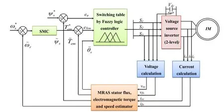
Fig.1 Structural diagram of fuzzy-DTC applied to asynchronous motor supplied by conventional two-level inverter
Fuzzy logic is a pragmatic approach to artificial intelligence, and provides fuzzy logic allows significant improvements in the performance of electric machines,especially the asynchronous motor.The fuzzy concept used in this article is based on the principle of DTC whose torque and flux errors are directly used to choose the switching state of the inverter.A fuzzy controller is used to replace the hysteresis comparators and the classic switching table.The three controller inputs are the position θ, the torque error eTemand the stator flux error eψ(Eqs.(1), (2) and (3)), and the outputs represent the switching states of the inverter (S1, S2and S3)).
The block diagram of Fig.2 summarizes the operation of fuzzy logic control.It has three main blocks: Fuzzification, Inference and Defuzzification.
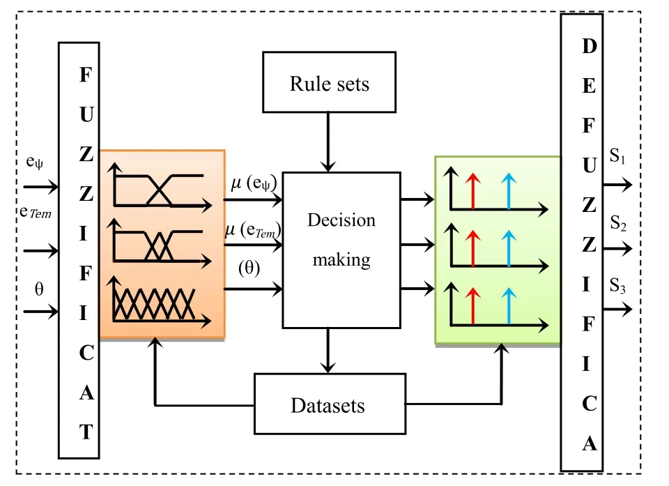
Fig.2 Block diagram of fuzzy controller
2.1 Fuzzification block
Firstly, this block establishes value ranges for the membership functions from input variables, and secondly,it performs a conversion of the input data into suitable linguistic values considered as fuzzy sets.Trapezoidal(Fig.3a) and triangular (Fig.3b) membership functions were chosen; the stator flux error input is composed of two fuzzy sets (linguistic variables): N (negative) and P(positive).Three fuzzy sets form the membership functions of the electromagnetic torque error: N (negative), Z(zero) and P (positive) were considered.In order to have a fine adjustment, the stator flux angle universe is divided into six fuzzy sets from θ1to θ6where the stator flux evolution space is considered in the (α, β) reference frame over six sectors (Fig.3c).
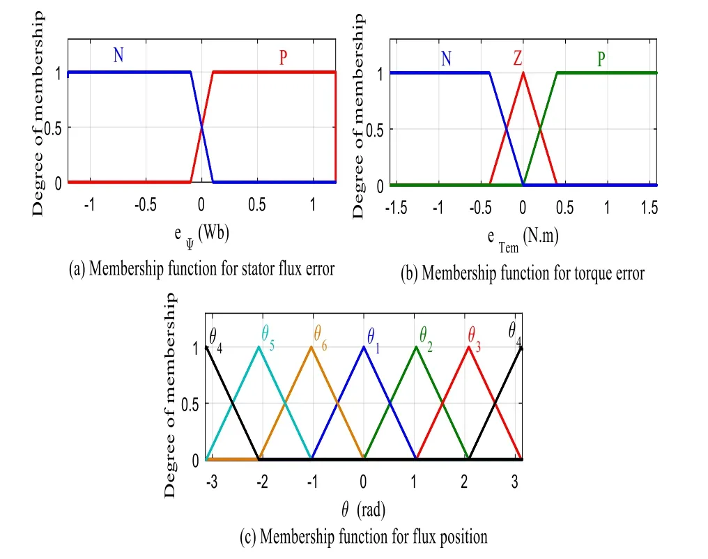
Fig.3 Input membership functions
The output variable representing the switching states of the inverter is divided into three output singletons (S1, S2,S3) under two fuzzy sets (zero and one) (Fig.4).
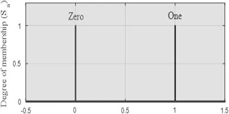
Fig.4 Output membership functions
2.2 Basis of control rules and inference mechanism
Based on linguistic variables, the fuzzy regulator uses inferences with several rules.The basis of the rules reflects the knowledge acquired by the operator who handles the process to be controlled [14].A system of fuzzy rules allows description, in the form of linguistic rules, of a transfer function between the input and output variables.The direct fuzzy torque control has 36 rules; all these rules are shown in Table 1.The inference method used is that of MAMDANI based on decision (Max–Min) [6].

Table 1 Basis of the adopted rules
2.3 Basis of control rules and inference mechanism
This block establishes value ranges for the membership functions from the output variables and then performs defuzzification which provides a non-fuzzy control signal from the inferred fuzzy signal.The most recognized and used methods to do this process are those based on the centre of gravity and maximum calculation.In this study,the latter method is used.
3 PI‑DTC‑SPWM with multilevel inverter
The block diagram of the overall system is shown in Fig.5, it can be divided into a control part (constant switching frequency DTC), a power part (multilevel inverters with the asynchronous motor) and an observation part which allows the motor quantities to be evaluated.The modulation technique used is that of SPWM which employs different carriers in order to construct all the necessary commands for the switches.Sinusoidal pulse width modulation is adopted here for its simplicity and low computation time [15].

Fig.5 Improved DTC strategy based on SPWM and PI regulators by powering the motor with multilevel inverter
The equations expressing the engine model according to the rotary frame (d, q) are:
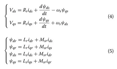
The stator field-oriented method is based on aligning the d axis with the stator flux vector and keeping the quadratic component of the stator flux equal to zero(ψqs=0,ψds=ψs).
Therefore, the electromagnetic torque expression can be written as:

The rotor currents and flux equations are:

After calculation, the stator voltages are therefore:

with

Ts=as the stator and rotor time constants, respectively.Is the angular sliding speed.Both electromagnetic torque and stator flux regulations is based on PI proportional-integral controllers.The transfer functions of the controlled quantities in open loop are respectively:
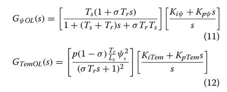
The block diagram of the control is shown in Fig.6.
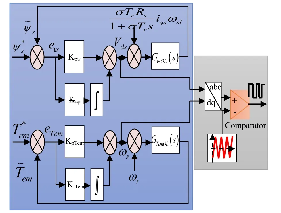
Fig.6 Stator flux and electromagnetic torque regulating blocks
4 Design of sliding mode technique for speed control
The sliding mode technique is mainly designed in two stages; the first is the choice of the sliding surface ensuring the conditions of stability, and the second is the control law design which maintains the trajectory on the sliding surface[16].The mechanical equation of the engine is defined by:

The sliding surface is synthesized from the tracking error and the relative degree.The control law must force the system outputto follow its reference; by minimizing the tracking error defined as:

From Eq.(13) the relative degree of the system is n = 1 so the sliding surface can then be defined as:

To ensure that the sliding surface can be reached and that the state variable slides across the surface to reach the equilibrium point in finite time, the following Lyapunov condition must be fulfilled [17]:

Because of the non-linearity of the motor and the uncertainties of its parameters; the sliding mode command is composed of an equivalent commandand a discontinuous one that consists of an evaluation function to ensure convergence.


To guarantee system stability, the coefficient κωmust be strictly positive.
5 Control variables estimation
The estimation of control variables is a crucial phase for the perfect fulfilment of the motor control.We propose three estimators: the stator flux model reference adaptive system, the sliding mode observer and a dual structure observer which allows operation with the sliding mode observer at low speed and to switch, at high speed,towards the SMRAS estimator which is the combination of SMO and MRAS.
5.1 Stator flux model reference adaptive system MRAS
The proposed stator flux MRAS structure is formed by two models; the first is the reference model which introduces the real system and the second is the adjustable model presenting the estimated system.
Reference model:

Adjustable model:
From the fixed coordinate system (α, β) the rotor equations can be described as (ωs= 0):

with:

The adjustable model can therefore be written according to the form presented in (23) in which rotor currents are replaced by their expressions in (22):
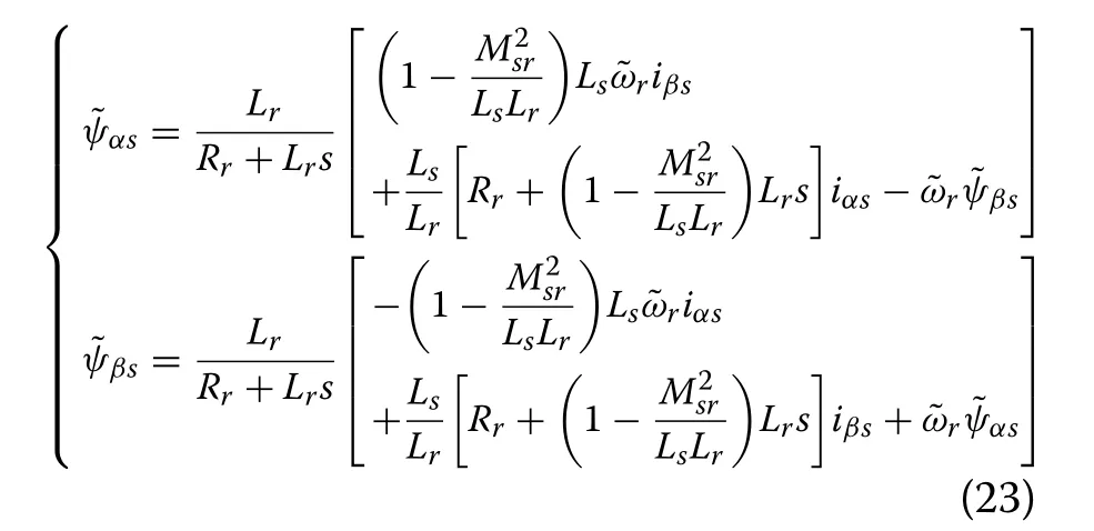
The MRAS principle is to compare the reference with the adjustable states.The error of this comparison intended for the corrector is:

The stator flux error state equation based on the adjustable and reference models is given as:
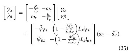
The adaptation mechanism that is proposed to estimate the motor speed is written as [18]:

with
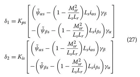
denoted by Kpsand Kisadaptation gains (Fig.7).
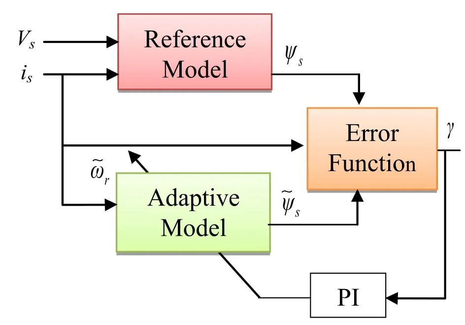
Fig.7 Stator flux model reference adaptive system (MRAS)
5.2 Sliding mode observer
The synthesis of the sliding mode observer is carried out from the model of the machine involving the flux and stator currents, then [19]:
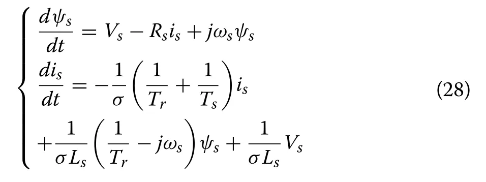
Hence the system of equations:
SIis the sliding surface which is a function of the difference between the estimated measured current:

A proportional-integral regulator is modelled so as to force the error convergence to zero.KI is a chosen constant to ensure stability and attractiveness towards the sliding surface (Fig.8).

Fig.8 Stator flux sliding mode observer (SMO)
5.3 Dual observer SMO‑SMRAS
The principle of SMRAS is to replace the reference model block in the MRAS structure by a sliding mode observer.This combination relatively decreases the ripples of the motor outputs.On the other hand, SMO produces satisfactory performances at low speed, while MRAS performs better at high speed.The idea of the dual observer SMO-SMRAS is to estimate speed with SMO at low speed and then switch to SMRAS at high speeds (Fig.9).
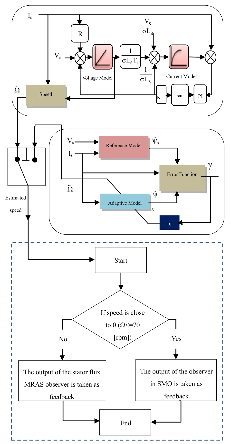
Fig.9 Dual observer SMO-SMRAS
6 PI‑DTC‑SPWM and fuzzy logic for driving
a sensorless asynchronous motor
Recently, the association of DTC with sophisticated and intelligent tools has enabled a revolutionary development in machine performance [4].However, the combination of a multilevel inverter with intelligent control such as fuzzy logic complicates the installation and greatly increases the computation time.In this regard, the linear PI-DTC-SPWM approach which is an independent structure of the inverter topology is the right choice for multilevel converter installations.
The aim of this section is to present a comparative and critical study between three enriched control systems of the asynchronous motor.The first installation combines the advantages of DTC and fuzzy logic control techniques by feeding the motor through a conventional two-level inverter.The second and third consist of applying PIDTC-SPWM to the same motor supplied by a three-level then five-level inverter.For all three installations, a sliding mode regulator is used in the outer loop for speed regulation.The feedback information is evaluated first by MRAS and then by the dual observer SMO-SMRAS.
6.1 Comparison of FL‑DTC with two‑level inverter and PI‑DTC‑SPWM with three‑level and five level inverters using MRAS estimator
Here we undertake comparative evaluation of the performance of three systems, namely, FL-DTC with two-level inverter and PI-DTC-SPWM with three-level then fivelevel inverters.For all three installations, the stator flux adaptive reference adaptive system is used to estimate the control variables and a sliding mode block is adopted for closed loop speed regulation.Simulations are made under the same conditions; two load torques are applied;0.8 N m at t = 0.3 s and 1.5 N m at t = 1.75 s.A ramp speed variation is introduced at the instant t = 0.75 s(from 20 to 800 rpm).Then there is another instantaneous variation (from 800 to 1325 rpm) and an instantaneous inversion of the direction of rotation (from 1400 rpm to − 1060 rpm) is applied at t = 1.5 s and t = 2.4 s.
6.1.1 Speed response
From to the Figs.10, 11 and 12, it is clear that the two controls have shown satisfactory performance and dynamics, and the rotor speed response time and the trajectory tracking are very good.Moreover, the analysis shows that speed response for PI-DTC-SPWM control with three-level and five-level inverters is characterized by a marked minimization of the ripples with a margin of 0.12% compared to FL-DTC command with two-level inverter (0.49%).In addition, the MRAS structure associated with PI-DTC-SPWM with three-level and five-level inverters shows great robustness regarding load torque disturbances.On the other hand, in Fig.10 (zoom 2) the FL-DTC displays a slight disturbance due to the application of the load torque.
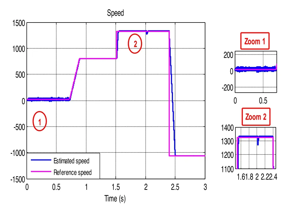
Fig.10 FL-DTC estimated speed response
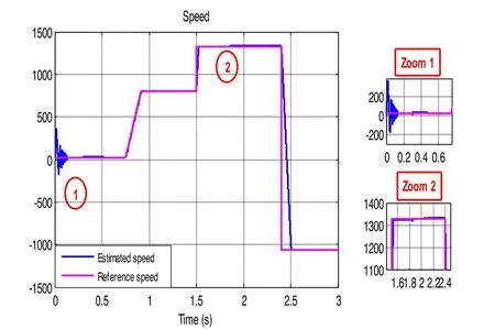
Fig.11 PI-DTC-SPWM with three-level inverter estimated speed response
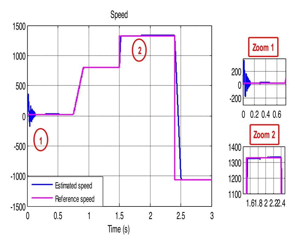
Fig.12 PI-DTC-SPWM with five-level inverter estimated speed response
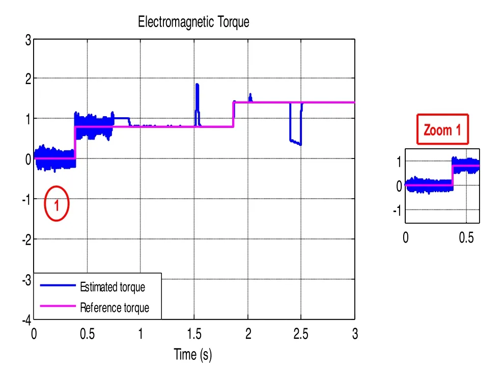
Fig.13 FL-DTC electromagnetic torque response
6.1.2 Electromagnetic torque response
Figures 13, 14 and 15 show that the estimated electromagnetic torque perfectly follows the load torque with good dynamics for the three systems.On the other hand, during the whole low-speed region operation, FLDTC shows persistent ripples of 75%, while, PI-DTCSPWM causes ripples that last only 0.1 s.These brief ripples could only be caused by the estimator structure which fails to keep up with the rapid dynamics of the motor during its start-up.It should also be observed that the three installations exhibit practically the same behaviour whether during the steady state or during speed variation.
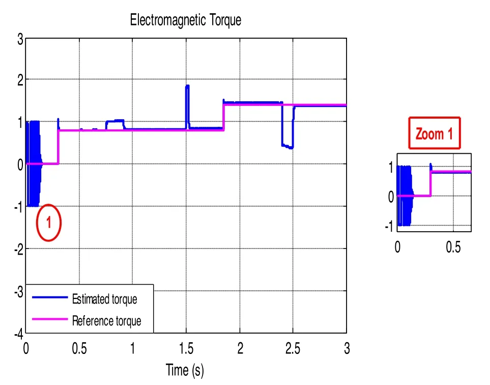
Fig.14 PI-DTC-SPWM with three-level inverter electromagnetic torque response
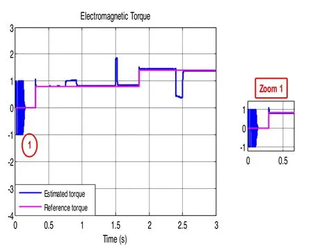
Fig.15 PI-DTC-SPWM with five-level inverter electromagnetic torque response
6.1.3 Stator currents response
Analysing the results shown in Figs.16, 17 and 18, the most important finding is that PI-DTC-SPWM strategy with three-level or five-level inverter provides appreciable performance regarding reduction of stator current ripples.Another remark that needs emphasis is that the use of a five-level inverter provides a strong reduction in the demanded current during the instantaneous change of speed at 1.5 s.
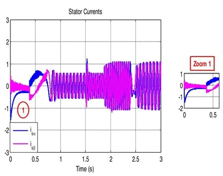
Fig.16 FL-DTC stator current components

Fig.17 PI-DTC-SPWM with three-level inverter stator current components

Fig.18 PI-DTC-SPWM with five-level inverter stator current components
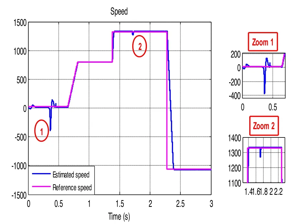
Fig.19 FL-DTC estimated speed response

Fig.20 PI-DTC-SPWM with three-level inverter estimated speed response
6.2 Comparison of FL‑DTC with two‑level inverter and PI‑DTC‑SPWM with three‑level and five level inverters using dual observer SMO‑SMRAS
The simulation constraints are the same as the previous paragraph except for the use of the dual observer SMO-SMRAS.
6.2.1 Speed response
Figures 19, 20 and 21 represent the dynamic response of the motor speed for the three installations, it correctly follows the trajectory of its reference, with minimal error during transient phases and zero static error during steady-state phases.FL-DTC shows a marked decrease in fluctuations at low speed (almost zero) but underwent a strong disturbance at the moment of the load application(zoom 1).It is also weakly affected by the application of the load at 1.75 s (zoom 2).PI-DTC-SPWM maintains slight ripples during the motor starting phase.These are much lower with the five-level inverter.On the other hand, it is completely insensitive to load application.

Fig.21 PI-DTC-SPWM with five-level inverter estimated speed response
6.2.2 Electromagnetic torque response
For FL-DTC, the ripples are strongly attenuated (Fig.22)but it shows disturbances during load application.With PI-DTC-SPWM, the estimator switch is completely unnoticed yet small ripples at low speed and during motor starting phase are still displayed (Figs.23, 24).

Fig.22 FL-DTC electromagnetic torque response
6.2.3 Stator currents response
Unlike FL-DTC (Fig.25), the starting current is strongly limited with PI-DTC-SPWM (Figs.26, 27) and the inrush of current during instantaneous variation of speed is much weaker.The currents waveform in the steady state is regular for the three systems.
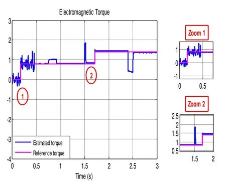
Fig.23 PI-DTC-SPWM with three-level inverter electromagnetic torque response
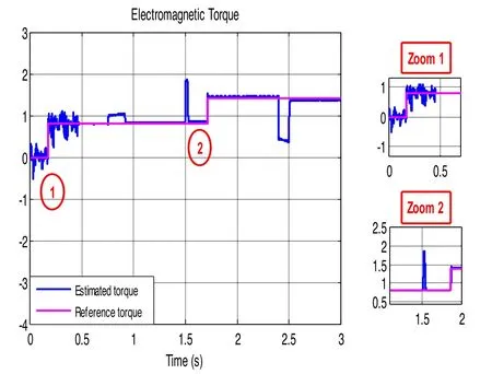
Fig.24 PI-DTC-SPWM with five-level inverter electromagnetic torque response
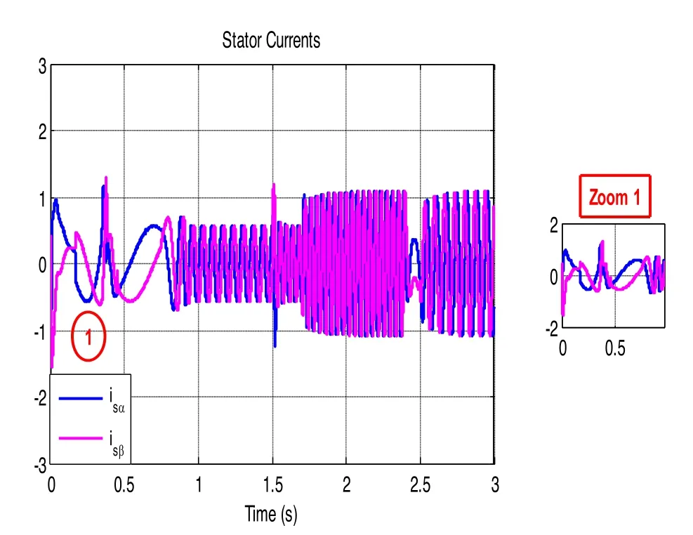
Fig.25 FL-DTC stator current components
Motor parameters: Power = 300 W, Ls= Lr= 3.62 H, Lm= 3.317 H, Rr = 14.762 Ω, Rs= 28.571 Ω,J = 0.0008183 kg.m2, P = 2, f = 0.000474 N.m.s/rd.
7 Conclusion

Fig.26 PI-DTC-SPWM with three-level inverter stator current components

Fig.27 PI-DTC-SPWM with five-level inverter stator current components
This article provides a comparative and critical study of two control strategies of an asynchronous squirrel cage motor.The first is DTC based on fuzzy logic applied with the usual two-level inverter, the second is simple PI-DTC-SPWM control based on pulse width modulation and PI controllers applied with a five-level inverter.Our contribution is to adopt a dual structure estimator between the SMO at low-speed and the SMO-SMRAS at high-speed for the two installations.The simulation results clearly show that the PI-DTC-SPWM with a five-level inverter has almost similar performance to the DTC based on fuzzy logic applied to the motor with a conventional two-level inverter.This was achieved by adopting the new structure estimator SMO-SMRAS.The results should be very interesting especially for high and medium power industrial installations where the use of multilevel inverters is required.
Abbreviations
ANN: Artificial neural network; DTC: Direct torque control; FL: Fuzzy logic;MRAS: Model reference adaptive system; SMRAS: Sliding model reference adaptive system; NN: Neural network; NPC: Neutral point clamped; SMC:Sliding mode control; SMO: Sliding mode observer; SPWM: Sinusoidal pulse width modulation; SVM: Space vector modulation.
Acknowledgements
The authors would like to thank the anonymous reviewers for their helpful and constructive comments that would greatly contribute in improving the final version of the paper.They would also like to thank the Editors for their generous comments and support.
Authors’ contributions
SED and LL performed the study of Comparison between PI-DTC-SPWM and fuzzy logic for a sensorless asynchronous motor drive and engaged in modifying the paper and submit it to the Journal.They also checked the grammar and writing of the paper.All authors read and approved the final manuscript.
Funding
The work is not supported by any funding agency.This is the authors own research work.
Availability of data and materials
Data sharing not applicable to this article as no datasets were generated or analyzed during the current study.
Declaration
Competing interests
The authors declare that they have no known competing financial interests or personal relationships that could have appeared to influence the work reported in this paper.
杂志排行
Protection and Control of Modern Power Systems的其它文章
- A comprehensive review of DC fault protection methods in HVDC transmission systems
- Application of a simplified Grey Wolf optimization technique for adaptive fuzzy PID controller design for frequency regulation of a distributed power generation system
- A critical review of the integration of renewable energy sources with various technologies
- Operational optimization of a building-level integrated energy system considering additional potential benefits of energy storage
- An integrated multi-energy flow calculation method for electricity-gas-thermal integrated energy systems
- Sliding mode controller design for frequency regulation in an interconnected power system
