Model predictive control of grid-connected PV power generation system considering optimal MPPT control of PV modules
2021-08-24YingyingZhaoAiminAnYifanXuQianqianWangandMinminWang
Yingying Zhao, Aimin An,2,3*, Yifan Xu, Qianqian Wang and Minmin Wang
Abstract Because of system constraints caused by the external environment and grid faults, the conventional maximum power point tracking (MPPT) and inverter control methods of a PV power generation system cannot achieve optimal power output.They can also lead to misjudgments and poor dynamic performance.To address these issues, this paper proposes a new MPPT method of PV modules based on model predictive control (MPC) and a finite control set model predictive current control (FCS-MPCC) of an inverter.Using the identification model of PV arrays, the module-based MPC controller is designed, and maximum output power is achieved by coordinating the optimal combination of spectral wavelength and module temperature.An FCS-MPCC algorithm is then designed to predict the inverter current under different voltage vectors, the optimal voltage vector is selected according to the optimal value function, and the corresponding optimal switching state is applied to power semiconductor devices of the inverter.The MPPT performance of the MPC controller and the responses of the inverter under different constraints are verified,and the steady-state and dynamic control effects of the inverter using FCS-MPCC are compared with the traditional feedforward decoupling PI control in Matlab/Simulink.The results show that MPC has better tracking performance under constraints, and the system has faster and more accurate dynamic response and flexibility than conventional PI control.
Keywords: Grid-connected PV power generation system, Model predictive control, Maximum power point tracking,Inverter, Optimal value function
1 Introduction
In addressing global climate change, the proposal of reducing carbon dioxide emission and carbon neutrality has accelerated the speed of energy low-carbon transformation [1–3].This has stimulated the rapid development of solar energy, and the permeability of grid-connection photovoltaic (PV) has been increasing [4].MPPT and inverter control strategy in a grid-connected PV power generation system ensure that the system operates in a stable and optimal state of maximum power by adjusting the voltage and current dynamically [5].This improves the energy conversion efficiency, power quality and stability of system operation without increasing the hardware cost.
The MPPT control method is the main technology to improve the efficiency of a PV system [6].At present, most MPPT control algorithms do not consider the impact of irradiance and temperature mutation on tracking speed and system control accuracy, e.g., the traditional incremental conductance method [7] finds it difficult to meet the requirements of tracking efficiency when there are interference and constraints from the external environment.The MPPT algorithm in the case of external environment mutation has been studied in[8], while in [9], the mathematical model of PV modules under partial shadow interference is established, and the relationship between output characteristics of PV arrays and outside interference factors is analyzed.The MPPT algorithm combining current control and disturbance observation method is proposed in [10].However, the above methods have high power consumption and find it difficult to consider both the tracking speed and the control accuracy when the external constraints change rapidly.
The grid-connected PV inverter control technology has become a research hotspot.Traditional control methods include linear methods, such as feedforward decoupling control based on PI regulation [11], and nonlinear methods, such as proportional resonance control [12].The former needs the PWM modulation module, while the static and dynamic performance of the system depend on the PI regulator.Although the latter has good dynamic performance, the switching frequency is not fixed, which makes the harmonic filter design difficult.With the improvement of digital processors, new control methods have been proposed, including fuzzy, adaptive and predictive control.The fuzzy logic control strategy of a gridconnected PV inverter is used in [13], while fuzzy rules and membership functions of fuzzy control depend on experience, which has some limitations, and the control stability needs to be improved.Reference [14] proposes an adaptive control method for a 3-phase inverter in the distributed generation system.The design of adaptive control is complex.The parameter adjustment is not only time-consuming, but also needs to be tuned under various working conditions.Predictive control adopts strategies of multi-step test, rolling optimization and feedback correction, and mainly includes deadbeat, repetitive [15]and model predictive control (MPC) [16–18].Because MPC can effectively overcome the uncertainty and nonlinearity of the process and deal with various constraints of spatial state variables, optimal control can be achieved by selecting the control mode that minimizes the evaluation function after establishing the system predictive model.Reference [19] studies the performance verification method of a finite control set model predictive control (FCS-MPC) strategy applied to the power electronic converter, and evaluates the performance of the algorithm using statistical model checking.Reference [20]studies the weighting factor design based on an artificial neural network of a converter under MPC, whereas in[21], MPC is applied to modular multilevel converters.The strategy of FCS-MPC is introduced into the voltage source converter and applied to an AC microgrid system in [22].However, the above methods are focused on converters, whereas research on new energy power generation systems has been limited.This paper combines a PV power generation system with MPC to realize fast tracking of the maximum power point of PV arrays and optimization of the inverter control performance.
In order to achieve the optimal control of a grid-connected PV power generation system, and maximize the utilization of solar energy, MPC strategies for PV modules and the inverter are proposed, respectively.From the linear PV array model obtained by model identification, a model predictive controller is designed for modules.By predicting the incident light wavelength, the maximum cut-off spectral wavelength is found and filtered to reduce the module temperature and achieve maximum power tracking.The FCS-MPCC algorithm is then applied to the inverter current control in thedqcoordinate system.The voltage vectors are evaluated through the predictive model and the optimized value function is established in each PWM sampling period.The voltage vector which minimizes the value function is used for the next sampling period to generate the switching control signals for the inverter.Finally, the system is simulated in Matlab/Simulink to demonstrate the performance in steady-state and dynamic operation.It shows that MPC can track the maximum power point of PV arrays and has an ability for fast current regulation.It also verifies the effectiveness of FCS-MPCC for a 3-phase grid-connected PV inverter.
2 Grid‑connected PV power generation system model
The grid-connected PV power generation system consists of PV modules, a DC capacitor, a 3-phase inverter bridge, RL filters, step-up transformers, etc.[23], and its typical topology is shown in Fig.1.Given the output characteristics of the PV cell, the PV array converts the absorbed solar energy into direct current under the control of MPPT, and the inverter converts the DC power to AC power, which is then transmitted to the power grid after filtering and boosting [24].

Fig.1 Topological structure of grid-connected PV power generation system
2.1 Mathematical model of PV array
In practical application, PV modules connect multiple single PV cells to transmit electrical energy.The relation between the output current and voltage of the PV array is given as:

where ILis the photo-generated current and Iscis the reverse saturation current.K is the Boltzmann constant,q is the electron charge, T is the ambient temperature,and A is the diode factor.Rs,Rpare the equivalent series and parallel resistances, respectively.
When sunlight irradiates, only a small part of the incident radiation is transformed into electrical energy by PV cells, while a large part of the energy increases the module temperature through heat transfer.However, the influence of irradiance and temperature on the output power are diametrically opposite, and the relationship between the PV module temperature and output power is given as:

where Cmoduleis the module heat capacity, Tmis the module temperature, qsw,qlware the short and long wave radiations of the incident light, respectively.qconvis the heat exchange and Poutis the output power.
2.2 Mathematical model of 3‑phase PV grid‑connected inverter
Considering all possible switching states of the 3-phase inverter, there are eight combinations.The inverter switching states are defined as:

where k =a,b,c is the three-phase sequence.
According to Kirchhoff’s voltage law and switching function, the mathematical model of an inverter in the 3-phase static coordinate system is shown as:

where ia,ib,icare the inverter output currents, udcis the DC bus voltage, and ea,eb,ecare the 3-phase grid voltages.Through Clark transformation, the 3-phase static coordinate system is transformed into the αβ coordinate system, and the inverter output voltages are:
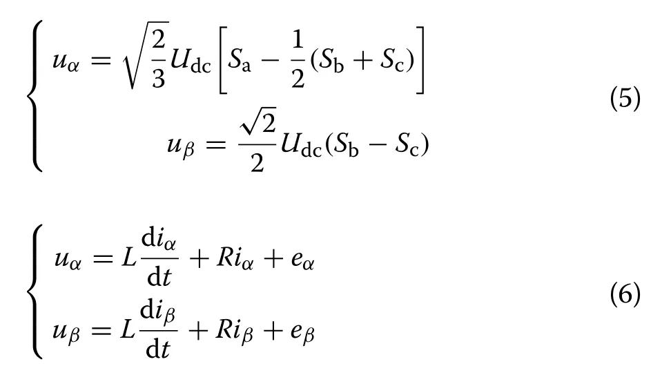
where uα,uβand iα,iβare the inverter output voltages and currents in the αβ coordinate system, respectively.eα,eβare the grid voltages in the αβ coordinate system.
By aligning the grid voltage synthesis vector E and thed-axis of thedqcoordinate system [14], the inverter output active power and reactive power in thedqcoordinate system are obtained as:

From (7), it can be seen that the active current idand reactive current iqhave a linear relationship with P,Q ,respectively.By independently adjusting the active and reactive currents, the inverter output active power and reactive power can be decoupled and separately controlled.
3 MPPT control of PV modules based on model predictive control
MPPT has become the key technology to increase output power, improve photoelectric conversion efficiency and decrease power generation cost [25].The influence of temperature on power generation efficiency is negative,so when the surface temperature of the PV module rises,the photoelectric conversion efficiency reduces [26].Therefore, the MPC controller is designed to predict the influence of incident light wavelength on module temperature and power, control the active filter to filter the maximum cut-off spectral wavelength, and dynamically adjust the relationship between module temperature and optimal output power, so as to minimize module temperature while maximizing output power at the same time.This not only achieves the purpose of maximum power tracking, but also improves power generation efficiency and durability.Figure 2 shows the structure block diagram of a model predictive controller for PV modules.
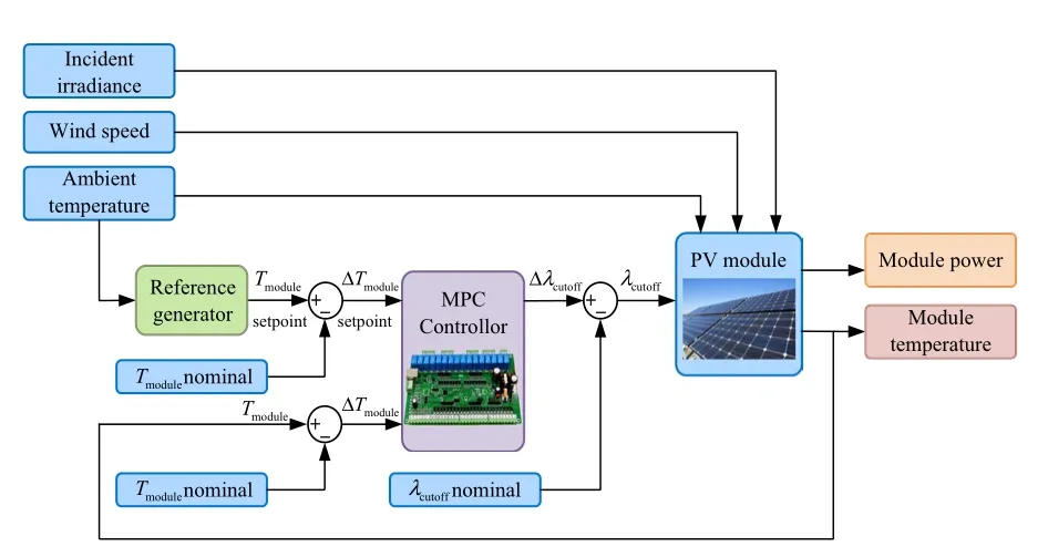
Fig.2 The structure block diagram of MPC controller of PV arrays
3.1 Mechanism model identification of PV modules
To design a model predictive controller it is necessary to obtain a linear model of PV modules.The two-step change of ultraviolet cut-off wavelength λUVis set as the excitation signal of system input, and the infrared cut-off wavelength λIRis set as 1100 nm.The ambient temperature and wind speed are obtained from a data table.The reference module temperature Tm_f, the change of ultraviolet cut-off wavelength λUVand the actual output power Poutare shown in Fig.3.
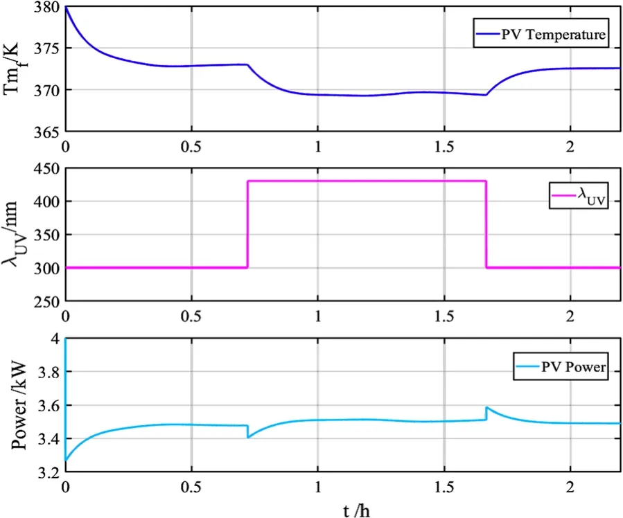
Fig.3 Input parameters and output power of model identification
In order to ensure that the PV modules fully reach a stable state, the total simulation time is set to 2.22 h.Using the system identification toolbox in Matlab, the initial linearization model is generated by a subspace identification method, which is then further optimized by the prediction error method.The coefficients of the state space equation obtained by the identification toolbox are given in Table 1, and the fitting curve between the actual output of the system and the linear model is obtained, as shown in Fig.4.The fitting degree reaches 92.36%.Final prediction error (FPE) is 0.01307, and mean squared error (MSE) is 0.01287.

Table 1 Coefficients of state space equation of the linearized model
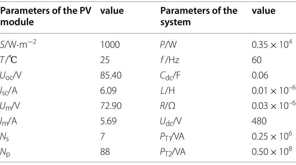
Table 2 Parameters of the simulated system
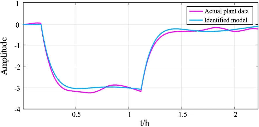
Fig.4 Fitting curves of actual plant data and linear model
3.2 Design of the model predictive controller for PV arrays
3.2.1 Theory of model predictive control
MPC is a model-based closed-loop optimal control strategy [27], and the mathematical model describing the research object in discrete form is given as:

where k is the sampling time, u is the input vector, y is the output vector, and x is the state variable.When the input and output variables are defined as U and Y , the output prediction sequence is defined as:

whereF =[CA CA2··· CANp]T, and

The objective function is defined as:

When the predictive control achieves the optimal control objective, the objective function takes the minimum value, as:

The predicted value of the state variable at the next time is:


The output prediction value of the system is:

From the above inference, the structure of the MPC system is shown in Fig.5.
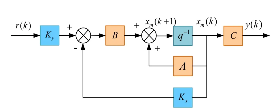
Fig.5 Structure block diagram of MPC system
3.2.2 Design process of PV modules MPC controller
The aim of the MPC controller is to maximize the output power by filtering the spectral wavelength to control the module temperature to track the reference value.Because the PV power generation is limited by the natural environment, the input, output and errors are constrained as follows:
To obtain the optimum output power at a given ambient temperature, the quantitative relationship between the ambient temperature and the module temperature is simulated according to the actual measurement data.The reference value of the module temperature is calculated as:

where Tambis the ambient temperature.
The simulation of an MPC controller of PV modules is established in Simulink/Matalb, as shown in Fig.6, with sampling time Ts=10 , prediction step NP=10 and control step Nm=2.

Fig.6 Simulation diagram of MPC controller of PV modules in Simulink
It can be seen from the results in Fig.7 that the module temperature is slightly lower than the reference temperature in the first hour of the simulation.The minimum value of λUVis 300 nm and the maximum value is 430 nm.This does not exceed the constraint range.In the second hour of the simulation, although there is a small fluctuation in the module temperature, the temperature tracking effect has been achieved.At about 2 h, the power gradually reaches the maximum value.Overall, MPC tracking performance is fast and good, and the purpose of MPPT is realized.
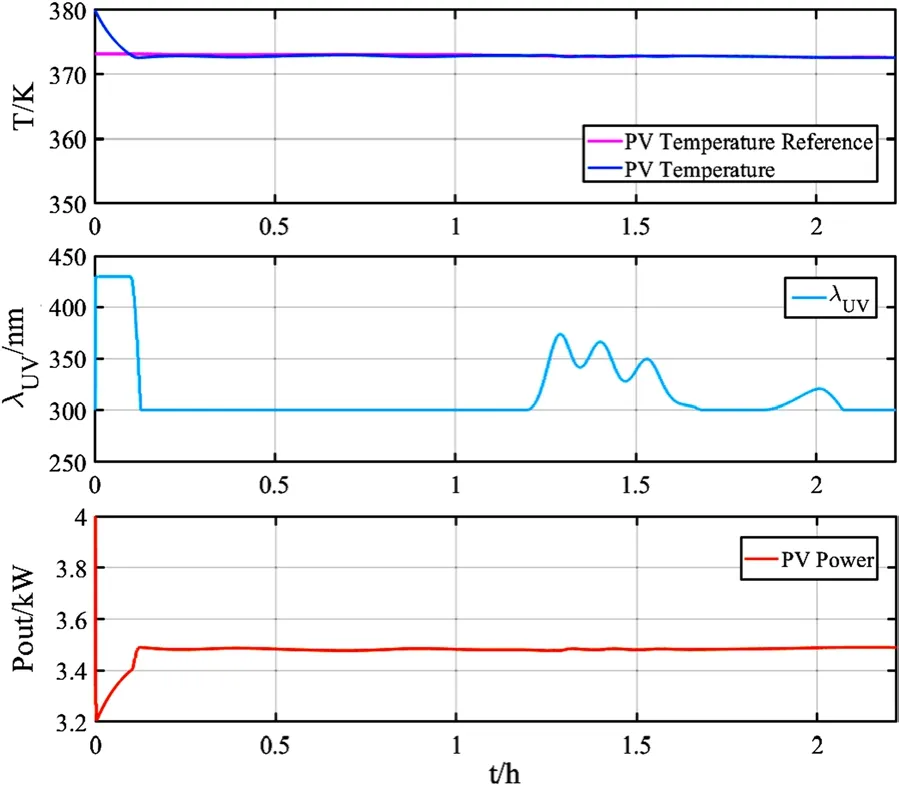
Fig.7 Simulation results of the MPC controller of PV modules
4 Control of the 3‑phase PV grid‑connected inverter
4.1 Feedforward decoupling control of inverter based on PI regulation
The feedforward decoupling control strategy based on double-loop PI regulation is a common PWM inverter control strategy.Its core is the design of a DC voltage outer loop, a current inner loop and PI regulators.The structure of inverter control strategy is shown in Fig.8.

Fig.8 Feedforward decoupling control structure of the grid-connected PV inverter based on PI regulation
In order to prevent the mutual influence between d,q axes in the current inner loop and eliminate the influence between active and reactive power, decoupling control is used, as:

where Kil,Kipare the proportional and integral regulation coefficients of the current inner loop PI regulators,respectively.
The feedforward decoupling control of an inverter based on a PI regulator combines SVPWM and feedforward decoupling control strategy.The control process is as follows: (1) Phase-locked loop is used to obtain the rotating flux position angleθ; (2)id,iqare obtained by coordinate transformation; (3) According to the feedback currents idref,iqref, the PI controllers are used to control the current inner loop to obtain ud,uq; (4)ud,uqare transformed into uα,uβthrough the dq to αβ coordinate transformation; (5)uα,uβare input to the SVPWM module to generate PWM signals to control the inverter.
4.2 Model predictive current control (MPCC)of the 3‑phase inverter
The MPCC technology uses current and past states to predict inverter current values in the next switching cycle derived from an accurate mathematical model of the system.The optimal value function is then used to select the optimal switch combination, so as to precisely track the current information [28].The prediction model and system optimization value function are determined as follows:
The predictive model is the basic element of the MPCC algorithm.The Forward Euler is used to discretize (6) to obtain the current prediction value at k+1 time, as:

where Tsis the sampling period.Transforming (16) intodqcoordinates yields the discrete space state prediction model of the grid-connected inverter, as:

where θ is the angle between thea-axis andd-axis, and id(k+1),iq(k+1) are thedqaxis components of the predicted current at k+1 time.
The optimal value function uses the quadratic performance index of prediction error to select the optimal combination of switching variables from different prediction values to minimize the error between the output current and the reference current at k+1 time.The value function is constituted by the quadratic difference between the predicted current value and the reference current value at k+1 time, as:

The FCS-MPCC algorithm flow is presented in Fig.9,and the structure of FCS-MPCC for the PV inverter is shown in Fig.10.The details of the control strategy mainly include the following 6 parts:
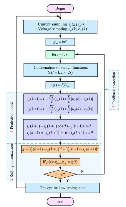
Fig.9 The algorithm flow of FCS-MPCC
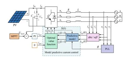
Fig.10 FCS-MPCC control structure of the PV inverter
1.The measurement module.Through real-time measurements of grid voltages, inverter currents and DC bus voltages, the actual operating data is transmitted to the prediction model.
2.PLL.PLL provides the phase angle for coordinate transformation and calculation of the prediction model.
3.Prediction model.The prediction model uses the recursive relationship in (17) to calculate the currentprediction value at k+1 time through the measured value of the system at k time.
4.Optimize the value function.The quadratic error of the reference current and the predicted current at k+1 time is taken as the optimization value function in (18).
5.Current reference.The active current reference comes from the outer DC voltage loop, i.e., the reference voltage Udcrefof the PV module is generated by MPPT control, and is then compared to the measured DC bus voltage Udc, before passing to a PI regulator.In order to be connected to the power grid with unit power factor, the reactive current reference is set to 0.
6.Signal driver.From the optimized value function, the switch state corresponding to the minimum value function is taken as the optimal switch state of the following sampling period, and the power semiconductor devices are switched accordingly.
5 Simulation verification and analysis
A simulation model is built in MATLAB to verify the feasibility of the control strategy.In order to implement the control effect, the FCS-MPCC algorithm is programmed through the S-function.The system model is shown in Fig.11, the sampling period is set to 2 × 10⁻⁵s, and the parameters of the simulated system are shown in Table 2.

Fig.11 Simulation model of a grid-connected PV power generation system
Figure 12a, b show the response curves of the PV array output DC voltage and current, and the active and reactive power into the grid during sudden changes of irradiance and temperature, respectively.As can be seen,when irradiance and temperature change suddenly at 1.0 s and 2.0 s respectively, the voltage is adjusted quickly to follow the maximum power point, and the MPPT tracking effect is effectively realized by the MPC controller.It is also seen that the FCS-MPCC algorithm quickly stabilizes the inverter output power at the maximum power point after disturbances at 1.0 s and 2.0 s.In addition, as shown in Fig.12, the increase of irradiance leads to a power increase indicating a positive relationship between the light intensity and PV output power,while temperature change is inversely related to PV output power.This is in line with the theory of PV power generation.
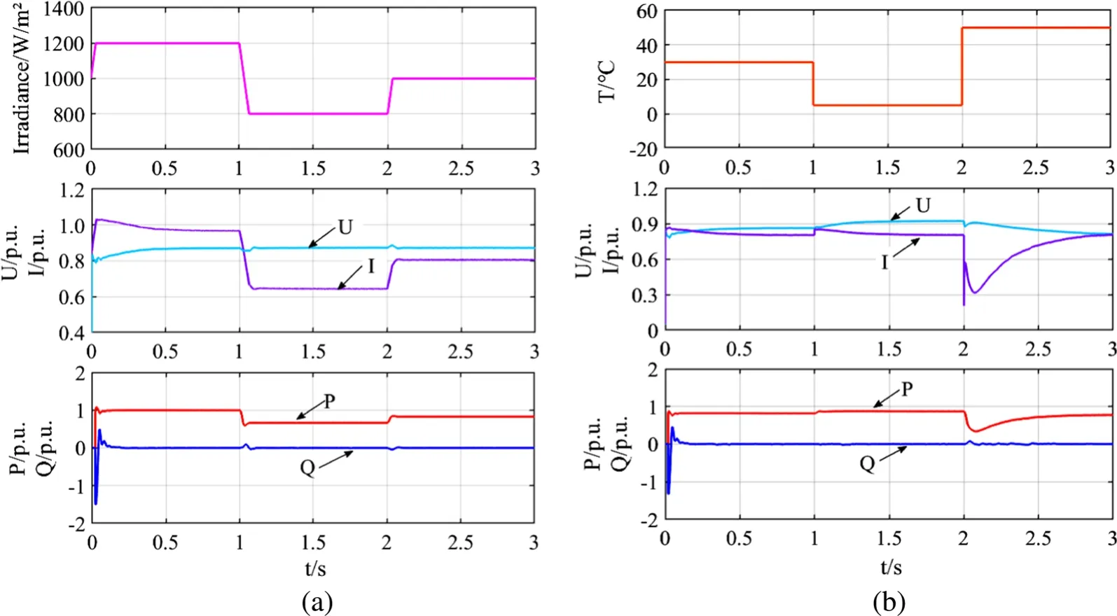
Fig.12 Response curves of PV arrays output during external conditions changes a PV arrays output during sudden change of irradiance, b PV arrays output during sudden change of temperature
Figure 13 presents the active powers into the grid and the voltages at the point of common coupling (PCC)under different grid faults.Four different types of faults are applied at 1.5 s, and cleared after 0.5 s.It is seen from Fig.13 that the active power and voltage can reach stable states within 0.2 s after fault clearance.This indicates that the grid-connected PV inverter with FCS-MPCC strategy can operate during faults with fast response.It can be seen from the partial enlarged diagram that the power oscillation and voltage fluctuation caused by the three-phase fault are the most severe, and have the greatest impact on the stability of the system, while the single-phase fault has the least impact.This is in line with practical working conditions.
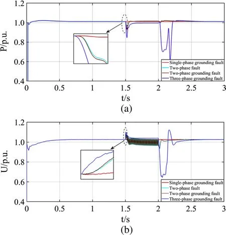
Fig.13 Response curves of system under short circuit faults a comparison of active powers into power grid under different faults, b comparison of voltages at PCC under different faults

Fig.14 A-phase waveforms of inverter with traditional feedforward decoupling PI control under initial condition a A-phase voltage and current at PCC, b harmonic analysis of A-phase grid current, c active and reactive power into power grid, d power factor
System performance with the traditional feedforward decoupling PI control and the proposed FCS-MPCC control method is shown in Figs.14 and 15, respectively.During the simulation, the active current reference idrefis provided by the voltage outer loop, with the reactive current reference iqref=0A .The parameters of the traditional feedforward decoupling PI controller are given in Table 3.

Table 3 Parameters of PI controller
It can be seen from Figs.14 and 15 that after initial transients, both methods reach stable operational states.The voltage and current are in phase, the system realizes the operation of unity-power factor, and the total harmonic distortion (THD) rate of grid current is less than 5%.This achieves the grid connection requirements.
Comparing the THD of the grid current shown in Figs.14b and 15b shows that the current THD is reduced from 4.82% with the traditional feedforward decoupling PI control to 2.54% with the proposed FCSMPCC.In addition, as seen from Figs.14c, d and 15c,d, the system under FCS-MPCC strategy only takes 0.08 s to reach stable operation, compared to 0.15 s with the traditional feedforward decoupling PI control.Overall, the quality of the output waveforms is greatly improved, and the control accuracy is significantly increased with the proposed FCS-MPCC method.
To test the stability of the system under abnormal operating conditions, the initial conditions of the system are changed.The references of the active and reactive currents are suddenly changed to idref=0.78A and iqref=−0.45A at 0.2 s.The simulation results with the FCS-MPCC method and the traditional feedforward decoupling PI control are compared in Fig.16.
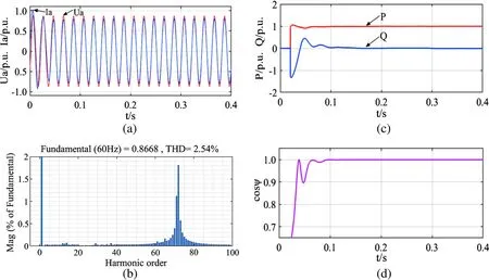
Fig.15 A-phase waveforms of inverter with FCS-MPCC under initial condition a A-phase voltage and current at PCC, b harmonic analysis of A-phase grid current, c active and reactive power into power grid, d power factor
As can be seen from Fig.16a, b, compared with the traditional feedforward decoupling PI control, id,iqcan better track idref,iqrefwith FCS-MPCC strategy.Comparing the response speed of the active power and reactive power shown in Fig.16c, d, FCS-MPCC strategy takes 0.05 s, while the feedforward decoupling PI controller requires 0.08 s, indicating better dynamic response of FCS-MPCC through decoupling control of active and reactive power.In addition, the reactive power transmission to the grid can be controlled by theq-axis current.
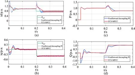
Fig.16 Comparisons of waveforms with FCS-MPCC and traditional feedforward decoupling PI control after changing initial conditions a active current, b reactive current, c inverter output active power, d inverter output reactive power
6 Conclusion
This paper addresses the optimal control problem of a grid-connected PV inverter system and optimizes the tracking performance of MPPT.To better deal with the small external constraints and system interference, an MPC-based MPPT method for PV arrays and an FCSMPCC strategy for the inverter indqcoordinate are proposed.The steady-state and dynamic performance of the MPC-based system are verified by simulation under different external constraints, faults, and change of initial conditions.The performance is also compared with the traditional feedforward decoupling PI controller.The following conclusions are obtained:
1.During sudden change of the external factors (ambient temperature, irradiance) or power grid faults, the grid-connected PV power generation system with MPC has rapid response speed, good anti-interference ability and satisfactory dynamic response.The MPC controller can quickly track the maximum power point of the PV array and output stable active power.This effectively increases the tracking sensitivity and accuracy of a PV power generation system,and improves the MPPT control performance.
2.Under FCS-MPCC, the grid current and voltage can be precisely controlled to operate in unity-power factor.Compared to the feedforward decoupling PI controller, the proposed FCS-MPCC results in lower current THD, better power quality, faster current tracking and improved dynamic performance.
Abbreviations
S: Irradiance; T: Ambient temperature; Uoc: Open-circuit voltage; Isc: Shortcircuit current; Um: Peak voltage; Im: Peak current; Ns: Number of PV modules in series; Np: Number of PV modules in parallel; P: Rated power of grid-connected PV power generation system; f: Power frequency; Cdc: Voltage stabilizing capacitor; L: Filter inductor; R: Filter resistor; Udc: The DC bus voltage; PT1: Rated power of 1#transformer; PT2: Rated power of 2#transformer.
Acknowledgements
Not applicable.
Authors’ contributions
All authors contributed to the study conception and commented on previous versions of the manuscript.YZ modeled the system, designed the algorithms of control strategy and wrote the paper.AA brought up the original conception and provided the technical guidance as a corresponding author.YX checked the data and tested simulation model in the paper.QW and MW contributed to revise and typeset the manuscript.All authors read and approved the final manuscript.
Author’s information
Yingying Zhao, (1997-), female, postgraduate, the main research direction is renewable energy access to Smart Grid.
Aimin An, (1972-), male, Ph.D.and Professor, Major in the artificial intelligence control technology, advanced industrial process control, renewable energy access to Smart Grid.
Yifan Xu, (1996-), male, postgraduate, the main research direction is renewable energy access to Smart Grid.
Qianqian Wang, (1995-), female, Ph.D.candidate, Major in the artificial intelligence control technology and advanced industrial process control.
Minmin Wang, (1995-), female, postgraduate, the main research direction is renewable energy access to Smart Grid.
Funding
This work was supported by National Science Foundation of China (61563032,61963025), Project supported by Gansu Basic Research Innovation Group(18JR3RA133), Industrial Support and Guidance Project for Higher Education Institutions of Gansu Province (2019C-05), Open Fund Project of Key Laboratory of Industrial Process Advanced Control of Gansu Province (2019KFJJ02).
Availability of data and materials
All data used or analyzed during this study are included in the published article.
Declarations
Competing interests
The authors declare that they have no known competing financial interests or personal relationships that could have appeared to influence the work reported in this paper.
杂志排行
Protection and Control of Modern Power Systems的其它文章
- A comprehensive review of DC fault protection methods in HVDC transmission systems
- Application of a simplified Grey Wolf optimization technique for adaptive fuzzy PID controller design for frequency regulation of a distributed power generation system
- A critical review of the integration of renewable energy sources with various technologies
- Operational optimization of a building-level integrated energy system considering additional potential benefits of energy storage
- An integrated multi-energy flow calculation method for electricity-gas-thermal integrated energy systems
- Sliding mode controller design for frequency regulation in an interconnected power system
