Super twisting sliding mode approach applied to voltage orientated control of a stand-alone induction generator
2021-08-24YacineBendjeddouAbdelhakimDebouchaLarafiBentouhamiElkheirMerabetandRachidAbdessemed
Yacine Bendjeddou,Abdelhakim Deboucha,Larafi Bentouhami,Elkheir Merabet and Rachid Abdessemed
Abstract To enhance the robustness and dynamic performance of a self-excited induction generator (SEIG) used in a standalone wind energy system (WES), a virtual flux oriented control (VFOC)based on nonlinear super-twisting sliding mode control (STSMC) is adopted.STSMC is used to replace the conventional proportional-integral-Fuzzy Logic Controller (PI-FLC) of the inner current control loops.The combination of the proposed control strategy with space vector modulation(SVM) applied to a PWM rectifier brings many advantages such as reduction in harmonics,and precise and rapid tracking of the references.The performance of the proposed control technique (STSMC-VFOCSVM) is verified through simulations and compared with the traditional technique (PI-FLC-VFOC-SVM).It shows that the proposed method improves the dynamics of the system with reduced current harmonics.In addition, the use of a virtual flux estimator instead of a phase-locked loop (PLL) eliminates the line voltage sensors and thus increases the reliability of the system.
Keywords: Self-excited induction generator, Virtual flux oriented control, Back-to-back converter,Super twisting sliding mode control, PI-fuzzy controller; wind energy
1 Introduction
A quarter of world’s population live in rural villages and isolated sites where most are not connected to electrical networks.Therefore they use fossil fuels for their energy needs, which causes ecological and economic problems.In recent years new energy sources have been developed to tackle climate change and pollution caused by fossil fuels.
The stand-alone induction generator connected to a wind turbine presents many advantages such as low cost and reduced maintenance being rugged, of simple construction, and with a brushless rotor (squirrel cage).However, the control of the output voltage of the generator transmitted to the consumer during changes in speed and load condition is challenging [1–4].
In [5–9], a vector controlled back-to-back converter is used between the SEIG and the load, while a simplified system with PWM rectifier and the load connected to its output in parallel with the DC bus voltage has also been proposed.The main objective of this technique is to ensure constant DC voltage at the output of the PWM rectifier for a constant amplitude and constant frequency at the output of the inverter.Generally, four PI controllers in a cascade configuration are used, i.e., two respective external loops for the flux and DC voltage, and two inner d- and q-axis loops for current control.In some cases, only two outer controllers are used for flux and DC voltage while the currents are controlled using hysteresis controllers.The major advantage of this control technique is its simplicity of implementation.However,the difference between the DC bus voltage and its reference reaches up to 5% for speed variation and 10% for load variation.Moreover, to obtain a decoupled control of the flux and torque it requires accurate SEIG parameters.Any variations of the stator and rotor resistances as well as magnetizing inductance can lead to a diminution of control performance due to the discrepancy between the real and reference flux vectors.Hence,it is necessary to estimate and compensate for the variation of these parameters [10], leading to a complicated control scheme.In order to solve the problem of SEIG voltage variation, large undershoot/overshoot of electromagnetic torque, and DC link voltage variation, many studies have proposed replacing the conventional PI by a Fuzzy logic controller (FLC) and a neural network controller.The results obtained are more efficient compared to conventional controllers though the dynamics can deteriorate in the event of significant variations in driving speed or load [11, 12].
Voltage oriented control (VOC) proposed and implemented by [9, 13–15] guarantees high dynamic and static performance via internal current control loops.The DC bus voltage at the output of the PWM rectifier is controlled by a voltage loop, in which a PI controller acts on the DC voltage error to generate references for the AC currents in the stationary (abc) or rotating (dq)reference frame.The PI current controller guarantees a good continuation of the input currents compared to the references, though the performance of this control technique depends largely on the quality of the applied current control technique.It has several advantages such as low current total harmonic distortion (THD), fixed switching frequency, and easy implementation.However,as this technique requires a phase-locked loop (PLL) to determine the phase angle, it requires line voltage sensors.
Another control technique proposed and implemented in [14] is composed of a diode bridge rectifier and a filter, and a PWM inverter.The purpose of this technique is to stabilize the amplitude and frequency output of the inverter for an autonomous energy generation system.It has good dynamics with a low harmonic current and voltage of the inverter (THD current =2–3%, THD voltage=0.12–0.2%), which are well within the 5% limit imposed by IEEE-519.However, the major drawback of such a system is the large stator current harmonics caused by the diode bridge rectifier.
Direct torque control (DTC) also has been proposed based on the orientation of stator flux [16–20].The control considers the finite control voltage vectors produced by the generator side PWM rectifier.The absence of the current control loop and park transformation makes the implementation of the DTC control simpler than the VOC, while it manifests itself by the rapid dynamic response.However, it has major drawbacks, such as the determination of switching states has to be based on information on the trends in flux and torque evolution from non-linear elements of the hysteresis type, and the variable switching duration, which leads to torque oscillations.
In this paper, a super-twisting sliding mode control(STSMC) regulator is proposed to replace the traditional(PI and PI-Fuzzy) controller.To enhance system robustness, system uncertainties are taken into consideration.The dynamic performance of DC voltage regulation is improved and the harmonics in the stator current are reduced.
VOC with virtual flux estimation using the proposed STSMC (STSMC-VFOC) with a two-level back-to-back converter is applied, where virtual flux is estimated as a function of the DC bus voltage and the control states of the rectifier.This technique makes it possible to simplify the control system and to improve the accuracy of estimation of the flux position.The principles of VOC,STSMC, SVM, and virtual flux estimator are combined for improved robustness and minimized ripples.To highlight the advantages of the proposed structure,simulation results are compared between the proposed strategy (STSMC-VFOC-SVM) and the conventional method (FLC-VFOC-SVM).
This rest of the paper is organized as follows: the modeling of the self-excited induction generator is briefly summarized in Section 2.VOC with virtual flux estimation is developed in Section 3 and the proposed STSMC strategy is described in detail in Section 4.The criteria employed to measure the efficiency of system response are presented in Section 5.The simulation results are presented and discussed in Section 6, and a conclusion is drawn in Section 7.
2 Mathematical model of induction generator
The mathematical model of an SEIG in a stationary d-q reference frame is described as [1–4]:
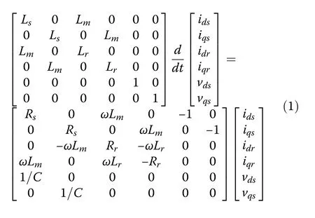
where Lsand Lrare the stator and rotor self inductances,respectively.Lmis the magnetizing inductance, and Rrand Rsare the rotor and stator resistances, respectively.C is the capacitance of the excitation capacitor connected at the stator terminals.
The SEIG model can also be describe by the state space equation as:

where

The variation of the magnetizing inductance is the main factor in the dynamic build up voltage and stabilization in SEIG [4, 5].It must be emphasized that the generator needs residual magnetism so that the selfexcitation process can be started.The variation of the magnetizing inductance Lmwith phase voltage used in this work is given in Fig.1.

Fig.1 Variation of magnetizing inductance with phase voltage
For self-excitation, the induction generator uses the battery on the DC side to provide the initial voltage across the capacitor and once the load voltage rises to a value higher than the battery voltage, it is automatically switched off by the diode.
3 Voltage oriented control
VOC with virtual flux estimation is implemented to improve the performance of the classical VOC which is based on PLL.
VOC or VFOC controls are similar to the fluxoriented vector control of induction machines.The method is based on the transformation between a stationary αβ coordinate and the synchronous rotating dq coordinate [9].VFOC provides better control of the rectifier under poor line voltage conditions (operation without an AC voltage sensor presents less noise because of the low pass filter behavior of the integrator used in the flux estimator).
3.1 Decoupled voltage control
The application of the decoupled control for the PWM rectifier makes it possible to decouple the currents Idand Iq, and to allow adequate regulation on each of the two separately[9]:

The decoupling between the d- and q-axis is done by the variables udand uqas:

where udand uqare the output signals from the current regulators.
After simplification, a decoupled state system is obtained as:

Currents of Idand Iqcan be controlled separately by the action on the components udand uq.Figure 2 shows the diagram of the current control loop.
Figure 3 shows the closed-loop transfer function of the current control and can be written as:


The DC voltage regulation loop generates the reference currentas shown in Fig.2.A Fuzzy-PI controller is used as presented in Fig.4.This is based on the error from two inputs and its variation [21].
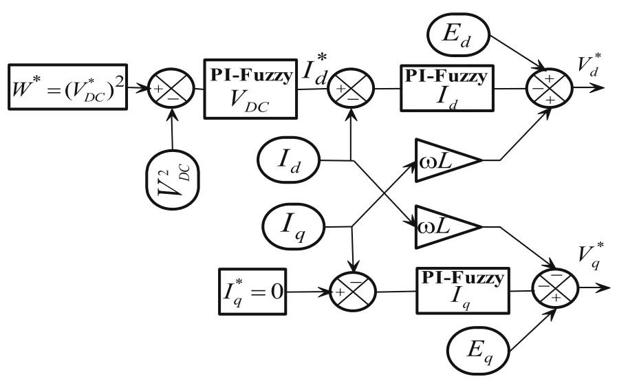
Fig.2 Schematic of decoupled control

Fig.3 Closed-loop of current control
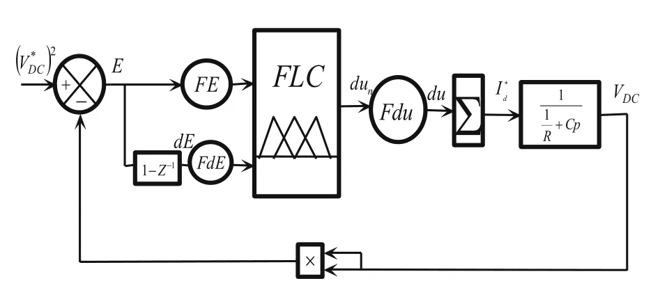
Fig.4 Closed-loop of DC voltage control
The expressions of the error (E) and its derivation (dE)are:

where VDCandare the DC voltage and its reference, respectively.
The output of the regulator is given by:

FE, FdE, and FdU are gains called “scale factor”.Figure 5 shows the function of membership of each input signal (E, dE).There are 7 fuzzy subsets for each variable giving 49 (7*7) possible rules, while the fuzzy subsets are[21]:NB (Negative Big), NM (Negative Medium), NS(Negative Small), Z (Zero), PS (Positive Small), PM(Positive Medium), and PB (Positive Big) [22–24] (Table 1).

Table 1 Rules bases

Table 2 Comparison performance criteria
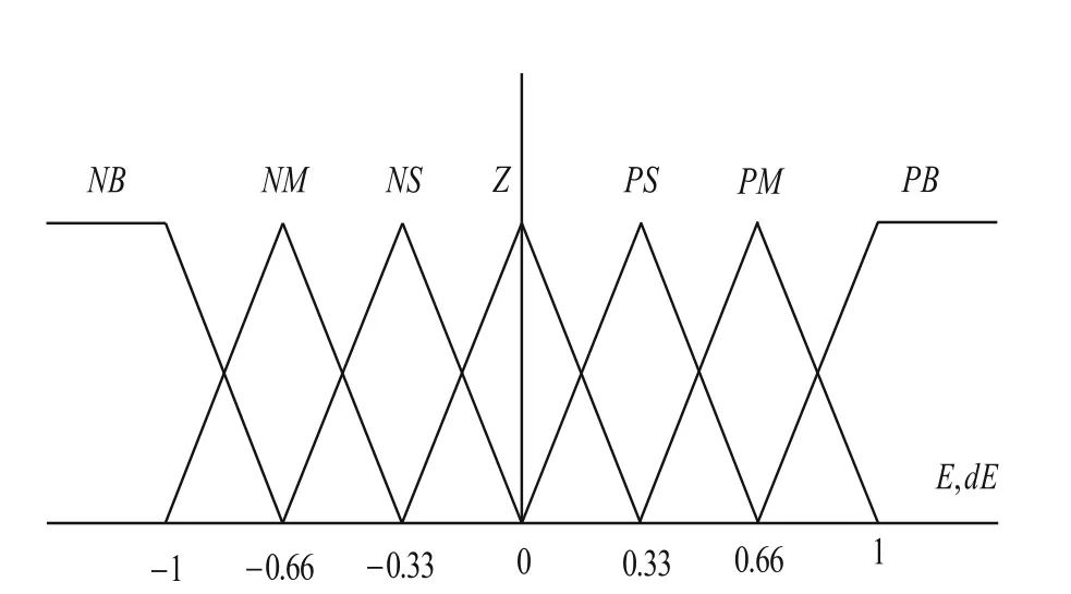
Fig.5 Membership function
3.2 Virtual flux estimation
Given that R and L represent the stator resistance and the stator leakage inductance of the virtual asynchronous generator [13], the components of the flux vector in the stationary αβ reference frame of the virtual generator connected to the terminals of the PWM rectifier are determined as:

The rectifier input voltages can be estimated as functions of the DC bus voltage and rectifier switching states as:

As the voltage drop across leakage inductance is negligible compared to the line voltage, the fluxes in the αβ axis are expressed as:

The virtual flux estimation method used for grid synchronization (in this case three-phase induction generator) is shown in Fig.6.
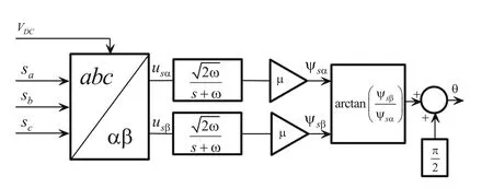
Fig.6 Virtual flux estimation for voltage sensorless 3-phase induction generator synchronization
The global schematic of the proposed control is presented in Fig.7.
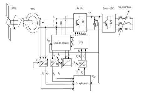
Fig.7 Algorithm of control
4 Super-twisting sliding mode controls(STSMC)
In this section, the design of current controllers based on STSMC is studied.A super twisting algorithm is designed to perform continuous control with a two-order sliding mode based on high order derivatives of the sliding mode surface.It can be an alternative solution to reduce the chattering phenomenon while keeping the same performance and robustness of sliding mode control [25, 26].
The super-twisting (ST) control law UST(t) is defined by two parts u1and u2, where u1is given by its derivative and u2is specified by the function of the sliding variable as [25]:


where λ and α are positive gains used to synthesize a robust super-twisting controller [27].
The nonlinearity can be regulated by changing the coefficient r in order to maintain stability.It must be positive and its value is within 0 ≤r ≤0.5.
Sufficient conditions to offer a finite time convergence are provided in[28]and are chosen as follows:

where α, λ, Φ and ΓMare positive constants, Φ is the positive bound of the uncertain function ϕ, ΓMand Γmare the respective positive upper and lower bounds of the uncertain function γ at the second derivative of the sliding surface given as [27]:

To guarantee the convergence of the sliding surface to zero in the presence of disturbances and uncertainties,the function ϕ(x,t) and γ(x,t) must satisfy the following conditions: Φ ≥ϕ and ΓM≥γ ≥Γm>0[29, 30].
In order to control the dq axis currents, a supertwisting sliding mode approach is considered.From the following equations:

the first derivative is written as:

From (15), the control based on the super twisting algorithm considered in [29] for the current controller is given as:

where the sliding variable S(d) and S(q) are the d- and q-axis current errors,respectively.
The gains are chosen according to the conditions stated in (16).The block diagram of STSMC is shown in Fig.8.

Fig.8 Super-twisting sliding mode control with virtual flux oriented control(VFOC)for induction generator
5 Performance criteria
The criteria employed to measure the efficiency of system response need take into account the variations in errors over the whole range of time.The three basic criteria commonly employed, i.e., Integral of absolute error(IAE), Integral of squared error (ISE), and Integral of time multiplied by absolute error (ITAE) [31] are evaluated as:


6 Simulation results and discussion
To verify the performance of the proposed control applied to the self-excited induction generator in remote areas, a Matlab-based simulation is conducted.Results presented in this section are for a 2 kW induction generator with the following electrical parameters: (Rs=1.7 Ω,Rr=1.2 Ω, ls=0.024 H, lr=0.023 H, Lm=0.023 H).During the simulation, the system is exposed to speed and load variations to test the performance of the control.The load contains three branches of resistances and inductances, at t=4 s the load changes from 200 Ω, 3 mH to 40 Ω, 1 mH, and then to 250 Ω, 8 mH at t=8 s.
The DC bus voltage at the output of the rectifier is shown in Fig.9.It demonstrates that the desired reference value of 700 V is tracked very quickly at the start without any significant overshoot.At t=4 s and t=8 s,the control system is subjected to load variations.As can be seen, the disturbances are rejected by the STSMCbased controllers with a response time of 0.02 s and overshoots of 0.7%.
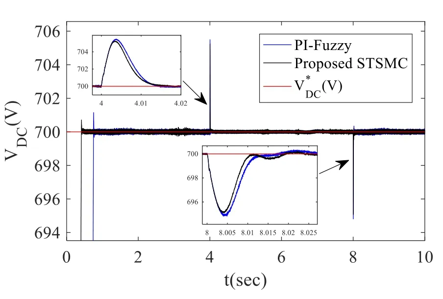
Fig.9 DC voltage.a With STSMC.b With PI-Fuzzy

Fig.10 Stator currents in (d,q)axis.a With STSMC.b With PI-fuzzy
Figure 10 shows the current tracking and the decoupling between the d- and q-axis of both the STSMC and PI-fuzzy controllers.However, the harmonic spectra of the stator current for the two controllers compared in Fig.11 show that current THD is lower in the STSMC technique (1.22%) compared to conventional PI-fuzzy controller (1.68%).Figure 12 (a) and (b) show the stator currents with the STSMC and PI-fuzzy controllers, respectively, while the rotor speed is shown in Fig.13.

Fig.11 Harmonic spectra of the stator current.a With STSM C.b With PI-fuzzy
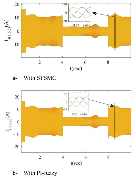
Fig.12 Stator current
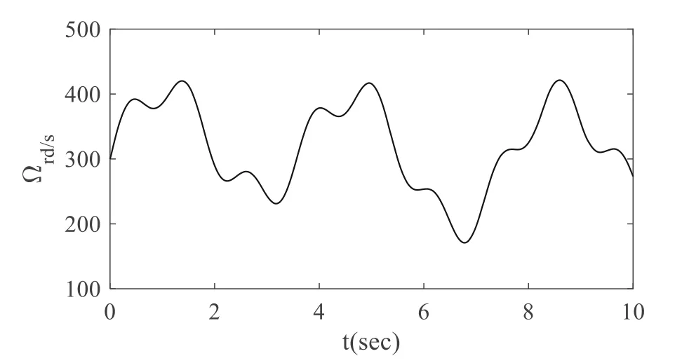
Fig.13 Rotor speed
Figures 14 and 15 show the output voltage and current of the inverter, while Fig.16 illustrates that the voltage amplitude follows its reference without overshoot.The output voltages generated by the SEIG change in amplitude and frequency as shown in Fig.17.
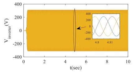
Fig.14 Output inverter voltages

Fig.15 Output inverter currents

Fig.16 Output inverter voltage amplitude
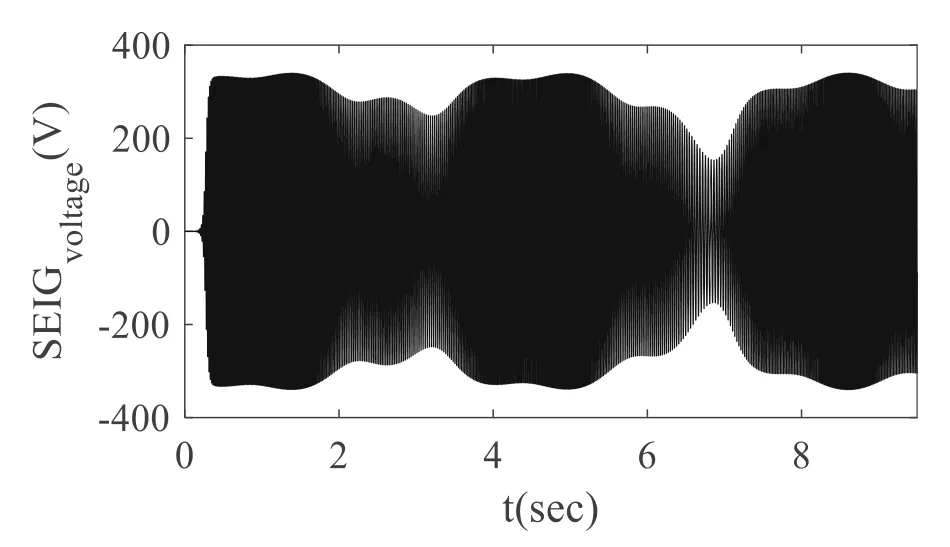
Fig.17 SEIG output voltages
The efficiency of the proposed STSMC technique based on the performance measures of IAE, ISE and ITAE are indicated in Table 2, which show better performance by the proposed controller.
7 Conclusion
In this paper, the super-twisting sliding mode approach applied to virtual flux orientated control (STSMCVFOC) of a stand-alone induction generator is studied and compared to the conventional PI-fuzzy control.Simulation results prove that the proposed STSMCVFOC control system assures better dynamic performance and illustrates a considerable reduction in current ripple compared to the PI-fuzzy controller.
8 Nomenclature
vds,vqs: Direct and quadrature stator voltages
ids, iqs: Direct and quadrature stator currents
idr, iqr:Direct and quadrature rotor currents
Ω: Synchronous speed
Ls,Lr: Stator and rotor self inductances
Lm:Magnetizing inductance
Rr, Rs: Rotor and stator resistance
C: Excitation capacitor
R, L: Stator resistance and stator leakage inductance of the virtual motor
ψsα, ψsβ: Stator flux in the αβ axis
VDC: DC bus voltage
usα,usβ: Line voltage in the αβ axis
isα, isβ:Line current in the αβ axis
ud, uq: Output signals from the current regulators
μ: Flux estimator adjustment coefficient
UST: Super-twisting control law
λ, α: Positive gains used to synthesize a robust supertwisting controller
α, λ: Positive constants
Φ: Positive bound
ΓM, Γm: Positive upper and lower bounds
γ: Second derivative of the sliding surface
ki, kp: Proportional and integral gains of the PI regulators
FE, FdE, FdU: Scale factors of the PI-Fuzzy regulators
Abbreviations
STSMC: Super-twisting sliding mode control; PI: Proportional-integral;VOC: Vector oriented control; VFOC: Virtual flux oriented control; SVM: Space vector modulation; SEIG: Self-excited induction generator; AC: Alternating current; PLL:Phase-locked loop; DC: Direct current; PWM: Pulse-Width modulation; THD:Total harmonics distortion
Acknowledgments
Not applicable.
Authors’ contributions
Bendjeddou was a major contributor in writing the manuscript.Deboucha has substantively revised the paper.Merabet performed the simulation examination.Bentouhami and Abdessemed analyzed and interpreted the simulation results.All authors read and approved the final manuscript.
Funding
This work is supported by the: Direction Générale de la Recherche Scientifique et du Développement Technologique (DGRSDT).
Availability of data and materials
Data sharing not applicable to this article as no datasets were generated or analyzed during the current study.
Declarations
Ethics approval and consent to participate
This article does not contain any studies with human or animal subjects performed by author.
Competing interests
The authors declare that we have no competing interests.
杂志排行
Protection and Control of Modern Power Systems的其它文章
- A comprehensive review of DC fault protection methods in HVDC transmission systems
- Application of a simplified Grey Wolf optimization technique for adaptive fuzzy PID controller design for frequency regulation of a distributed power generation system
- A critical review of the integration of renewable energy sources with various technologies
- Operational optimization of a building-level integrated energy system considering additional potential benefits of energy storage
- An integrated multi-energy flow calculation method for electricity-gas-thermal integrated energy systems
- Sliding mode controller design for frequency regulation in an interconnected power system
