Comprehensive power swing detection by current signal modeling and prediction using the GMDH method
2021-08-24SeyedAmirHosseiniBehroozTaheriHosseinAskarianAbyanehandFarzadRazavi
Seyed Amir Hosseini,Behrooz Taheri,Hossein Askarian Abyanehand Farzad Razavi
Abstract Power swing is an undesirable variation in power flow.This can be caused by large disturbances in demand load,switching, disconnection or reclosing lines.This phenomenon may enter the zones of distance relays and cause relay malfunction leading to the disconnection of healthy lines and undermining network reliability.Accordingly,this paper presents a new power swing detection method based on the prediction of current signal with a GMDH(Group Method of Data Handling) artificial neural network.The main advantage of the proposed method over its counterparts is the immunity to noise effect in signals.In addition, the proposed method can detect stable,unstable, and multi-mode power swings and is capable of distinguishing them from the variety of permanent faults occurring simultaneously.The method is tested for different types of power swings and simultaneous faults using DIgSILENT and MATLAB,and compared with some latest power swing detection methods.The results demonstrate the superiority of the proposed method in terms of response time,the ability to detect power swings of different varieties, and the ability to detect different faults that may occur simultaneously with power swings.
Keywords: Power swing, Distance relay, Power system protection, GMDH
1 Introduction
Distance relays are widely used in power systems to protect transmission lines [1, 2].Despite their excellent features and contributions to power system protection, these relays may malfunction during power swings, leading to the tripping of healthy lines.Such malfunction could lead to power system instability and cause a major power outage.To prevent this, distance relays are equipped with a power swing blocking (PSB) function.The mechanisms of power swing detection and PSB activation in distance relays have been the subject of many studies.
In [3, 4], several detection methods based on the rate of impedance change are proposed.These can distinguish between slow power swings and faults,and block the distance relay when necessary.However, they cannot detect fast power swings nor faults that occur simultaneously with power swings [5–9].Reference [5] proposes a power swing/fault differentiation method based on the observed resistance in the distance relay.This method functions on the idea that the resistance observed in the relay during a power swing is constantly changing whereas it remains largely constant during a fault.However, this method requires a long time to detect power swings.In [7], a power swing detection method based on a combination of a concentric impedance characteristic and continuous monitoring of apparent impedance is proposed, whereas in [10], power swings are detected based on the swing center voltage (SCV).In [11],power swings are detected using the Fast Fourier Transform (FFT) of the DC component of the current, though one of the problems of FFT-based techniques is on setting suitable threshold values for fault detection [12].In addition, such techniques use asynchronous sampling with a limited number of samples.This makes them vulnerable to problems such as spectral leakage and the picket fence effect[13, 14].In [15], wavelet transform is used to avoid the FFT problems.In this method power swings and simultaneous faults are detected based on the harmonics derived from a wavelet transform.Reference[16] uses a fast wavelet transform algorithm to detect symmetrical faults that occur simultaneously with a power swing, while in [17], power swings and faults are detected by applying the wavelet transform to impedance changes.In [18], wavelet transform analysis of current changes is used to detect faults with different resistances during power swings.
Reference[19]proposes a power swing detection method based on the window averaging of current.However, such a method may malfunction under multi-mode power swings, and it is unable to detect asymmetrical power swings.In[20],power swings are detected based on the rate of changes in the RMS values of current during faults and power swings.Although this method is capable of detecting high impedance faults during power swings, it cannot detect asymmetrical one-phase power swings induced by single-pole switching.In [21], faults are differentiated from power swings by analyzing the rate of instantaneous frequency changes.However, this method is noise sensitive and is unable to detect multi-mode power swings.A detection method based on the rate of changes in the average apparent power is proposed in [22].This can properly detect multi-mode power swings but not the asymmetrical ones.A method based on zero-frequency filtering is presented in[23]and can detect fast three-phase faults that occur at the same time as a power swing[24].However,it cannot properly detect multi-mode power swings and could malfunction when the signals are noisy.The detection method provided in [25] uses a fast wavelet transform, which can detect three-phase faults during power swings but requires a high sampling rate(20 kHz)and changes in sampling rate at different times.In[26],a detection method based on the rate of change in the kinetic energy signal is proposed.This method can detect various types of faults during power swings but underperforms during multi-mode power swings.Reference [27] proposes a new method based on the Fourier transform.It provides fast calculation and fault detection along with power swings.However, it lacks the capability to detect unbalanced power swings.In [28], a method based on the theory of signal compression is proposed which requires a lower sampling rate.However, although lower sampling rate leads to high-speed fault detection,it also increases the likelihood of misdiagnosis.A fault detection method with power swing based on mathematical morphology is proposed in [29].However, the method may make a false disconnection of healthy lines during a multi-mode power swing.A method based on the prediction of signal samples using phaselet transform is proposed in [30], though it needs a longer time for detecting faults that occur during a power swing and determining the appropriate threshold value is also very challenging.A method based on empirical mode decomposition is proposed in [31], which has the outstanding feature of being capable to detect a multi-mode power swing.However,the main limitation on its application is the strong dependence on the correct determination of the number of intrinsic mode functions (IMFs), as the presented method can lead to erroneous IMFs in networks with different topologies.
In summary, the methods in the literature all have shortcomings which limit their use.To address the problems,this paper presents a new power swing detection method based on the prediction of current signals by the Group Method of Data Handling (GMDH).The main advantage of the proposed method over its counterparts is its immunity to noise.In addition, the method can detect all types of stable, unstable, and multi-mode power swings and can properly distinguish all types of permanent faults that occur simultaneously with these power swings.Also, the performance of this method is independent of the network structure.The proposed method is tested on the standard IEEE 39-bus network and a standard 9-bus network for different power swings and simultaneous faults.The results demonstrate the success of the method in detecting all types of power swings and simultaneous faults.Moreover, a comparison of the results with those of existing relay protection methods shows its superiority in terms of response speed and the diversity of power swings covered.
The rest of this paper is structured as follows.The proposed method is presented in Section 2, which describes the GMDH neural network and explains how signals are predicted.Section 3 presents the results of the tests performed on the standard IEEE 39-bus network and a standard 9-bus network under different power swings and simultaneous faults.In Section 5, the proposed method is compared with the existing alternatives,and Section 6 draws the conclusions.
2 Power swing
Figure 1 is presented to better understand or illustrate the concept of power swing and instability in a power system.The electric power (Pe) and its maximum value(PMax) can be obtained in pu as [32, 33]:

where XTis the total network impedance and δ is the rotor angle (in electric radians).
According to Fig.1, if both transmission lines between buses A and B are active, the changes in P −δ are shown in Fig.2.In this state, for a given input mechanical power Pm, the output steady-state electrical power Pewill be equal to Pmand the operating point is at “a” as shown in Fig.2.If one of the lines is disconnected, the effective reactance XTwill increase and the changes in P−δ are also shown in Fig.2.As illustrated, in this state,the maximum power is reduced, while the rotor angle will rise to transfer the same steady-state power so the rotor angle δ0corresponds to the working point “b” in Fig.2.The swing equation is expressed as [32]:

Fig.1 Single-line diagram of a typical double fed network
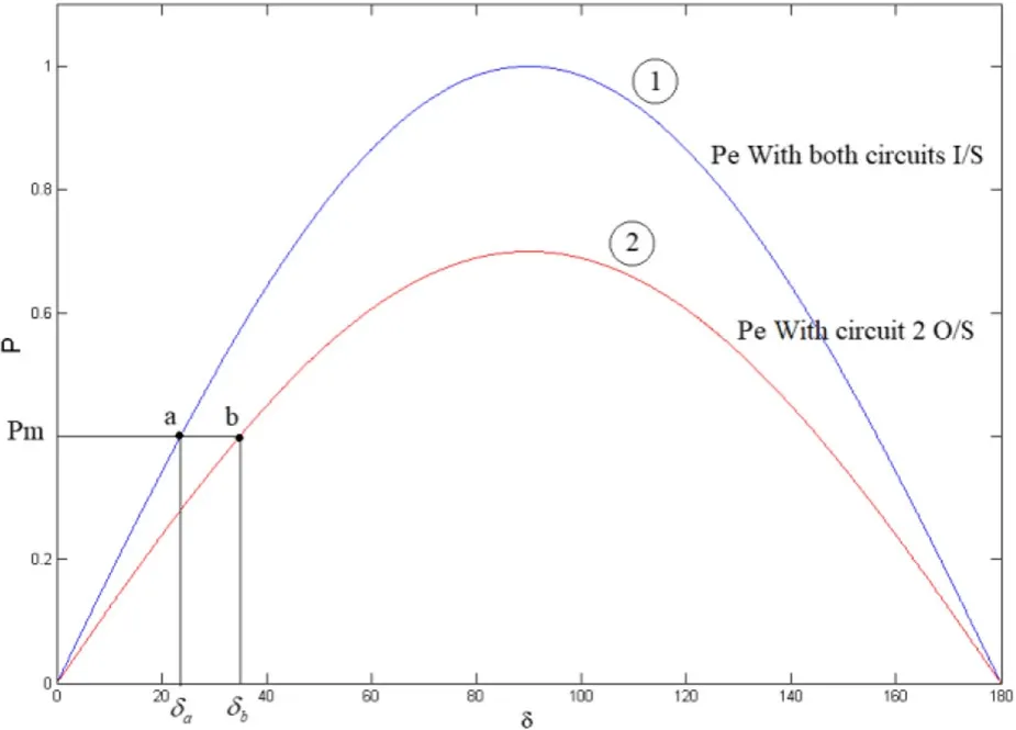
Fig.2 Changes in P −δ for the network in Fig.1

where Pmis the input of mechanical power(in pu),H is the inertial constant(in MWS/MVA),and t is time(in seconds).
3 Proposed method
3.1 GMDH neural network
With the rapid progress of artificial neural networks in recent decades, they have become a viable alternative to traditional computing methods.Artificial neural networks take a series of observations as the inputs of a training phase.This enables them to predict similar time series in the future.The GMDH neural network is a polynomial neural network that was first introduced by Grigorevich in 1968.
The reason for working with the GMDH model is its superiority over conventional neural networks.In [34], it is confirmed that the GMDH neural network performs much better than conventional neural networks (e.g., MLP and LSM Tree) in time series modeling.In addition, GMDH needs much less training time than Deep Learning methods and models such as LSTM, and does not require complex hardware for training.The basic GMDH model is shown in Fig.3,and can be expressed in the form of:

Fig.3 Basic GMDH model

where y is the system output, a0is a constant, aidenotes the weight coefficients,fidenotes the basic functions,and n is the total number of inputs.The basic model of(4)can be rewritten based on the Kolmogorov-Gabor polynomial as:

where x is the system input.The number of terms in (5)strongly depends on the number of inputs and can be calculated by:

According to(6),the number of terms in (5) rapidly increases with the complexity of the system.For example,the number of terms for 30 inputs reaches 1010as:

For such a large number, it would be very difficult to find its coefficients.The issue can be resolved by using the method presented in Fig.4,which uses a group of efficient models to reach a general model.This approach involves decomposing the problem of (5) into several problems with fewer unknown variables and then solving each of these smaller problems as parts of a larger problem.In this approach, partial models are obtained using the least-squares method.

Fig.4 Mechanism of using efficient models to reach a general model
Assuming that there are four inputs x1, x2, x3, and x4,the general model is given as:
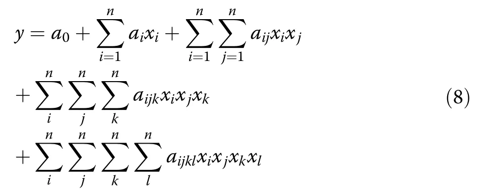
Equation (8) can be turned into multiple problems with fewer unknowns using the following:

In (9), Zijis the temporary output and c1- c6are the coefficients of the terms, which can be calculated by(10)–(19)shown below.
Figure 5 shows a simple artificial neural network model.In this simplified network, Z is computed based on xiand xjusing (9).To implement the procedure of Fig.5, all samples obtained from (9) should be turned into a vector similar to the following:

Fig.5 A simple artificial neural network model
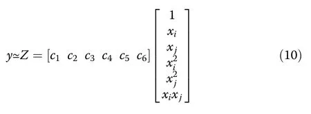
Equation (10)can be rewritten as:

If all existing samples are considered in (11), then there are:

Using (12)and(13), the general equation is formulated as:

To obtain the cTvalues, both sides of (14) are multiplied by XT,i.e.:

Multiplying by(XXT)−1on both sides of(15) yields:
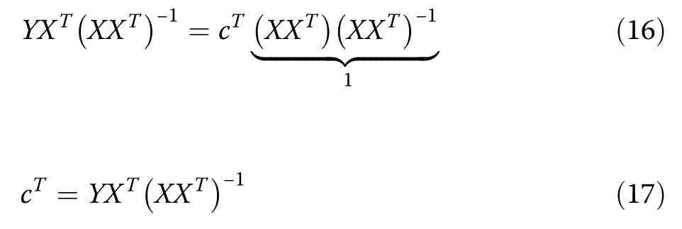
cTcan be calculated by having the right pseudoinverse of matrix X as:

According to (10)–(19) and Fig.6, the above procedure turns the four initial inputs into six, thus making the system more complex.To avoid this issue, a measure is proposed for choosing Zij’sbased on the type of problem.Using the proposed measure,a number of Zij’swill be selected and the rest will be discarded.Then, the selected Zij’swill be used to another layer and the previous steps will be repeated.The stopping condition is to reach one neuron.
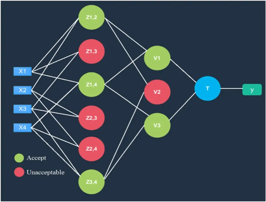
Fig.6 GMDH neural network model
3.2 Training of GMDH neural network
To function correctly, neural networks have to be trained with a wide variety of fault and power swing data.In this study, the GMDH neural network model is trained for the double-fed network shown in Fig.7.
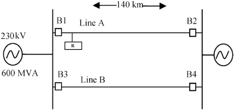
Fig.7 Double-fed 230 kV network
The training is performed using the data obtained from 16 simulations, the details of which are given in Table 1.In these simulations, the distance relay is placed to protect Line A.After applying various types of power swings to Line A, the outcomes are recorded for use in training.In this study, power swings are detected based on the difference between the predicted value and the real value of the signal.Therefore, these simulations are performed without injecting any faults in order to increase the difference between the predicted and real signals during the occurrence of a fault.
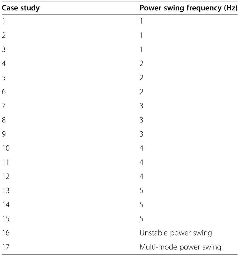
Table 1 Details of simulations performed on the network in Fig.7 to train the neural network model
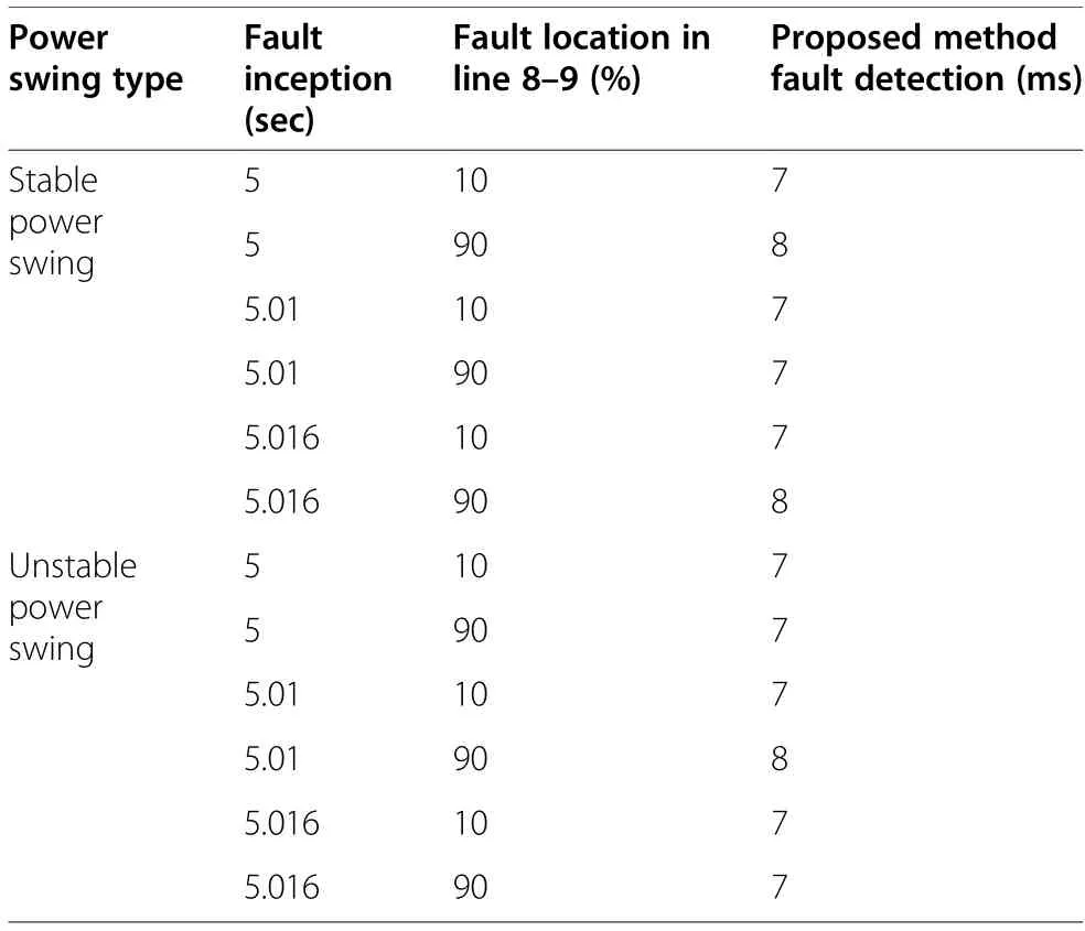
Table 2 Performance of the proposed method under different faults in the standard two-area network

Table 3 Comparison with alternative methods
Figure 8 shows the training of the neural network model, which consists of three sections, i.e., one for training data, one for test data, and the other for all data.In all three sections, the x-axis is the target output and the y-axis is the output of the neural network.The neural network functions correctly when the curve falls on the Y=T line (the line with a y-intercept of zero and slope of 1).As shown in Fig.8, the neural network performs very well for both training and test data and ultimately achieves a regression coefficient of 1 in all cases.

Fig.8 Training of the neural network model
3.3 Signal prediction
The parameters that need to be predicted during a power swing and after a fault can be expressed as [30]:
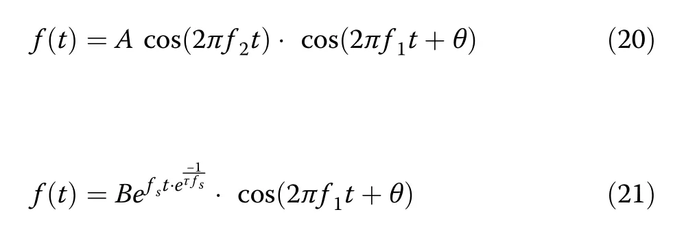
From the above equations, it can be deduced that current samples can be predicted more successfully under normal and power swing conditions than after a fault, because of the presence of a damping component during a fault.Under normal conditions, there is no DC component in the current waveform.It is thus necessary to eliminate the DC component from the real samples before comparing them with predicted values.The input current and the real samples can be expressed as:
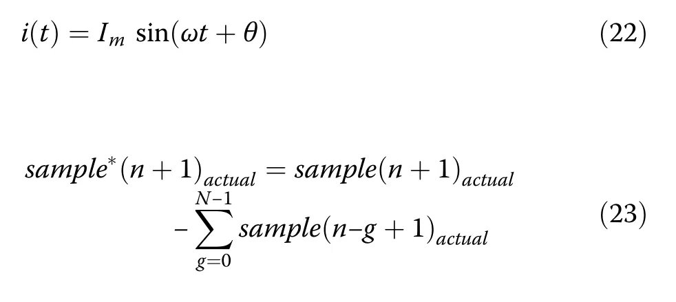
Thus, the difference between the predicted and real signal values can be calculated by:

Therefore, the effective difference between the predicted and real signal values is given as:

The outputs of (25) determine the state of the power network.If the RMSE is larger than the threshold value,a fault has occurred.In contrast, if the RMSE is smaller than the threshold value, the network is either in a normal condition or is experiencing a power swing.If the RMSE is lower than the threshold value and the impedance observed by the distance function falls within the protection zone, there is a power swing in the system.The algorithm of the proposed method is illustrated in Fig.9.
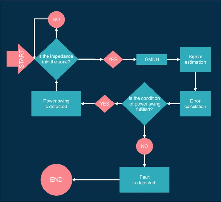
Fig.9 Algorithm of the proposed method
4 Simulation results
4.1 Test on the IEEE 39-bus network
The proposed method is tested and evaluated using the standard IEEE 39-bus network in the DIgSILENT software.The single-line diagram of this network is shown in Fig.10.This network consists of 39 buses, 10 generators, and 19 load points, which consume 6150.1 MW of active power and 1233.9 MVar of reactive power.The distance relay chosen for implementing the proposed method is placed on Bus 26 to protect Lines 26–29.Using DIgSILENT, a variety of power swings and faults are applied to the network.
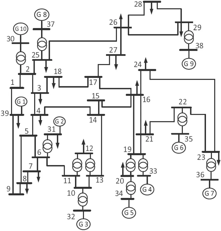
Fig.10 Single-line diagram of the standard IEEE 39-bus network
4.1.1 Stable power swing
A power swing occurs when the rotor angle of a generator advances or retards relative to others.This phenomenon may occur because of changes in load size and direction,line switching,loss of generator excitation,or faults.In the cases where the generator with the mismatching rotor angle does not experience pole slip and the system reaches a new equilibrium, it is said that a stable swing power has occurred.To simulate a stable power swing on Line 26–29, the breakers on the parallel Lines 26–28 and 28–29 are opened at t=1 s.The performance of the proposed algorithm under this power swing is shown in Fig.11a, while Fig.11b displays the impedance changes during the power swing.
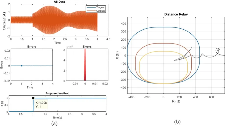
Fig.11 a Performance of the proposed algorithm under the applied stable power swing.b Impedance changes during the applied stable power swing
4.1.2 Unstable power swing
Unstable power swings occur when the events described in the previous section lead to the occurrence of pole slip in one or more generators.To simulate the strongest type of unstable power swing, the breakers at the parallel Lines 26–28 and 28–29 are opened at t=1 s, and a large load of 2000 MW and 200 MVar is then applied to Bus 26 at t=1.5 s.The performance of the proposed algorithm under this unstable power swing is illustrated in Fig.12a, while Fig.12b shows the impedance changes.As seen, the proposed algorithm is successful in detecting this unstable power swing and blocking the relay in time.
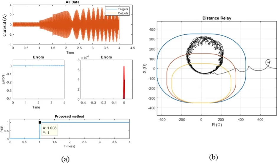
Fig.12 a Performance of the proposed algorithm under the applied unstable power swing.b Impedance changes during the applied unstable power swing
4.1.3 Multi-mode power swing
Multi-mode power swings occur when a power swing involves two or more machines and therefore current and voltage phasors are not completely sinusoidal [35].To simulate a multi-mode power swing, a three-phase fault is applied to Line 4–14.This fault starts at t=0.2 s and the line is tripped by the breaker at t=0.6 s.The performance of the algorithm under this power swing is illustrated in Fig.13a and the impedance changes during this multi-mode power swing are plotted in Fig.13b.As shown in Fig.13a, the proposed algorithm detects the multi-mode power swing and activates the PSB function accordingly.
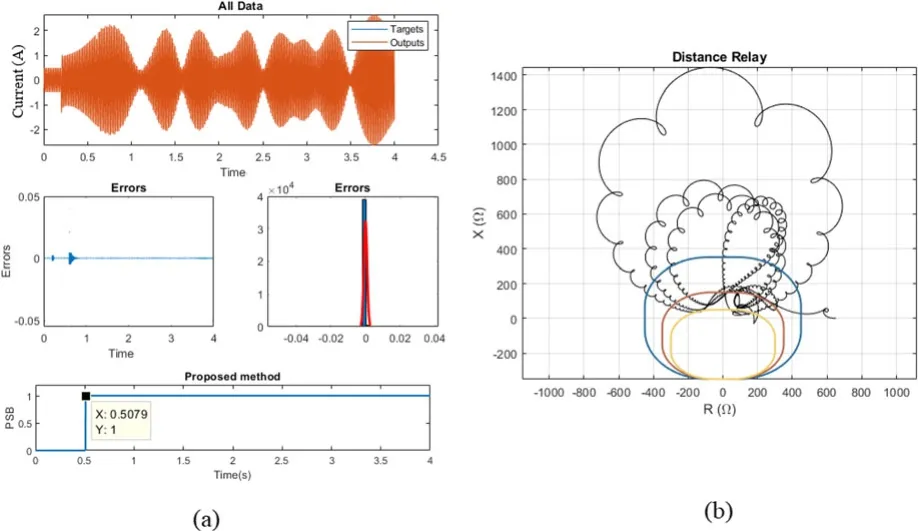
Fig.13 a Performance of the proposed algorithm under the applied multi-mode power swing.b Impedance changes during the applied multi-mode power swing
4.1.4 Single-phase fault occurring simultaneously with power swings
To evaluate the response of the proposed algorithm to single-phase faults, a single-phase line-to-ground fault is applied to Line 26–29.To create the power swing, the line parallel to Line 26–29 is tripped at t=1 s, while at t=3 s, a single-phase fault is applied to the same line.The performance of the proposed algorithm under this fault is illustrated in Fig.14a while Fig.14b shows the impedance changes.As shown in Fig.14a, during the power swing, the relay function is correctly blocked.After the occurrence of the fault, it is detected in 7 milliseconds and the PSB function is properly disabled.
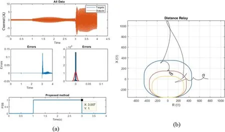
Fig.14 a Performance of the proposed algorithm under the single-phase fault occurring simultaneously with power swings.b Impedance changes during the single-phase fault occurring simultaneously with power swings
4.1.5 Three-phase fault occurring simultaneously with power swings
Because of the symmetrical nature of power swings, most existing power swing detection algorithms cannot properly distinguish between power swings and three-phase faults.In contrast, the proposed method is capable of detecting three-phase faults with high precision,an ability attributable to the conditions included in its mechanism and the use of the initial transient state of faults in the design.Given the defined conditions, when a fault occurs,the rate of change rises above the threshold value and the relay is thus unblocked.In the study,this fault is simulated by applying a three-phase fault to Line 26–29 at t=3 s,while the performance of the method is shown in Fig.15a with Fig.15b illustrating the impedance changes.As can be seen from Fig.15a, upon the occurrence of a power swing, the PSB function successfully blocks the relay, but once the three-phase fault occurs, the algorithm detects the fault and unblocks the relay.
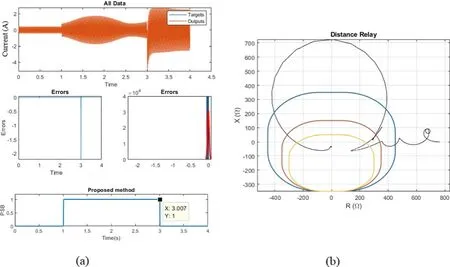
Fig.15 a Performance of the proposed algorithm under the three-phase fault occurring simultaneously with power swings.b Impedance changes during the three-phase fault occurring simultaneously with power swings
4.1.6 Effect of noise on the performance of the proposed method
Signals can be affected by white noise, which can severely undermine the accuracy of power swing detection algorithms [27, 28].To evaluate the performance of the proposed algorithm in the presence of noise, it is tested under an unstable power swing with white Gaussian noise.In the study, a white Gaussian noise signal which has a signal-tonoise ratio of 30 dB and a variance of 0.05, as shown in Fig.16,is added to the unstable power swing current signal.
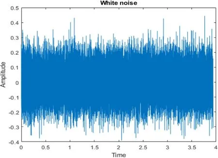
Fig.16 White Gaussian noise added to the unstable power swing
As shown in Fig.17, the proposed algorithm correctly detects the unstable power swing with white Gaussian noise and blocks the relay.
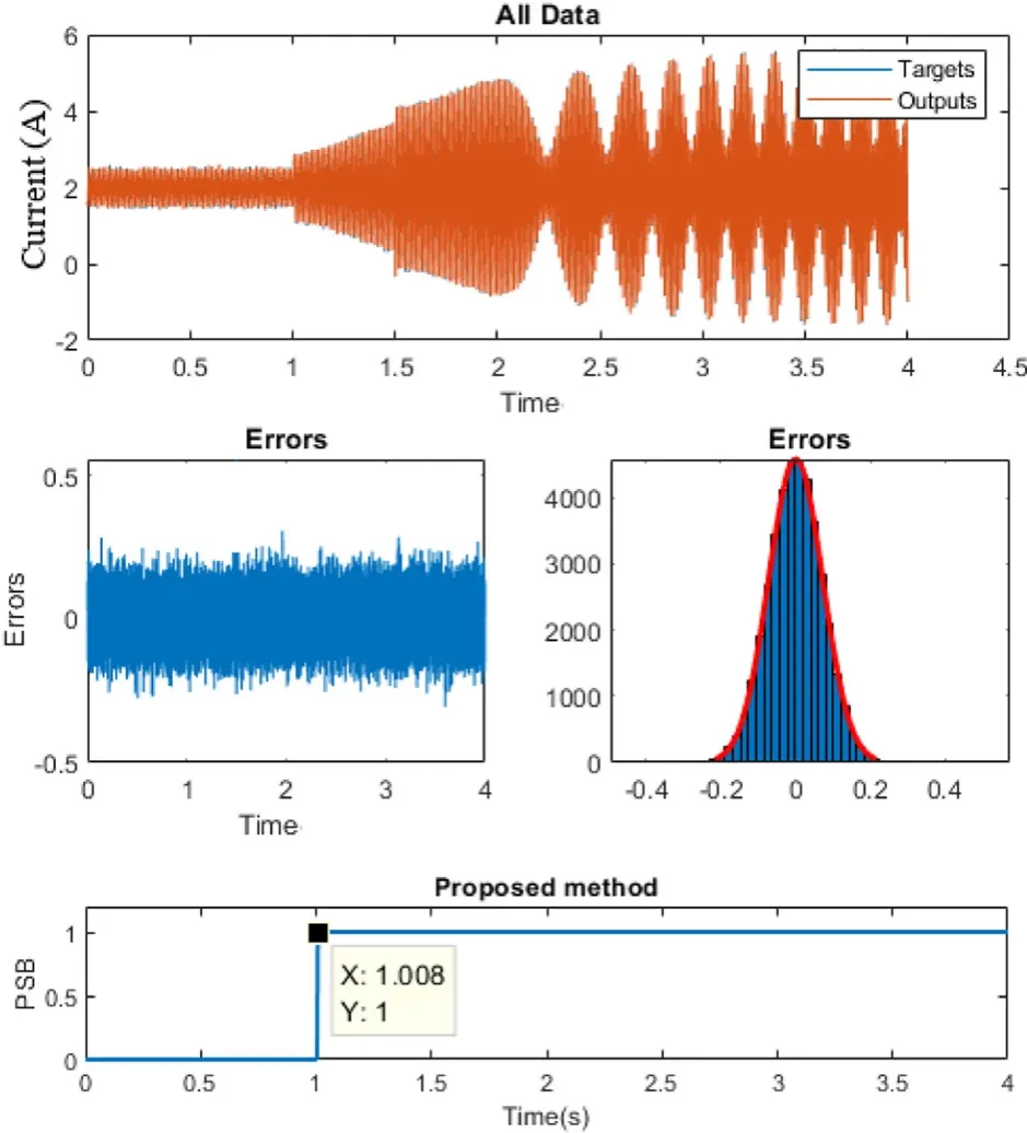
Fig.17 Performance of the proposed method under noisy signal
4.2 Test on the standard 9-bus network
The effect of different types of faults on the performance of the proposed method is studied on a standard 9-bus network.The single-line diagram of this network is displayed in Fig.18, and more detailed information about this network can be found in [23].
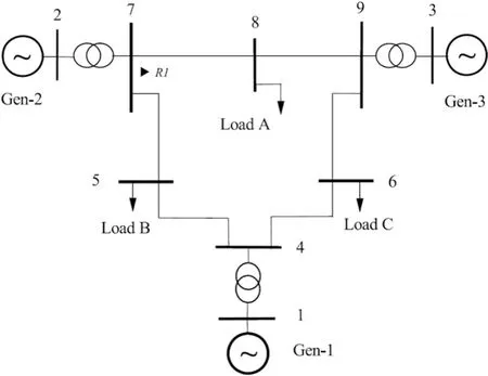
Fig.18 Single-line diagram of the standard 9-bus network
The results obtained using this standard 9-bus network are provided in Table 2.They demonstrate the ability of the method to detect all types of fast and slow power swings and the variety of faults that may occur simultaneously.For better evaluation of the proposed method, its responses to different faults applied at different times and positions are investigated.As shown in Table 2, the proposed method has a very high response speed and exhibits an adequate performance for all types of faults.
5 Comparison with the existing alternatives for protection relays
In Table 3, the proposed method and other existing power swing detection methods are compared in terms of performance under high impedance faults, multimode power swings, a three-phase fault with a phase angle of 180 degrees, and noisy signals.It shows that while other methods experience difficulty in dealing with high impedance faults and noisy signals, the proposed method performs very well in this area.
6 Conclusion
This paper has presented a high-performance highly reliable method for the detection of power swings and faults that may occur simultaneously.In the proposed method,a signal prediction mechanism based on GMDH is used to distinguish between power swings and faults.The proposed method is tested for power swings of the stable, unstable,and multi-mode variety and various types of single-phase and three-phase faults on a test network.The results demonstrate the ability of the proposed method to respond correctly and swiftly to different types of power swings and simultaneous faults.Compared to the methods commonly used in protective relays which have difficulties in detecting some types of power swings, the proposed method can detect all types of power swings.
Abbreviations
GMDH: Group Method of Data Handling;PSB: Power Swing Blocking;SCV: Swing Center Voltage; FFT: Fast Fourier Transform; IMF: Intrinsic Mode Function; MLP: Multi-Layer Perceptron; LSM: Liquid State Machine;LSTM: Long Short-Term Memory
Acknowledgements
Not applicable.
Authors’ contributions
The paper was a collaborative effort among the authors.SAH and BT,brings up the idea by GMDH for power swing blocking,performed the primary simulations and drafted the manuscript.HAA and FR, participated in enriching the manuscript (in theoretical idea and simulation section (IEEE 9-Bus power system)) and carried out the revising the manuscript (editing grammatical and lexical mistakes).All authors read and approved the final manuscript.
Funding
Not applicable.
Availability of data and materials
Please contact author for data requests.
Declarations
Competing interests
The authors declare that they have no competing interests.
杂志排行
Protection and Control of Modern Power Systems的其它文章
- A comprehensive review of DC fault protection methods in HVDC transmission systems
- Application of a simplified Grey Wolf optimization technique for adaptive fuzzy PID controller design for frequency regulation of a distributed power generation system
- A critical review of the integration of renewable energy sources with various technologies
- Operational optimization of a building-level integrated energy system considering additional potential benefits of energy storage
- An integrated multi-energy flow calculation method for electricity-gas-thermal integrated energy systems
- Sliding mode controller design for frequency regulation in an interconnected power system
