Electrical control strategy for an ocean energy conversion system
2021-08-24MuhammadNomanGuojieLiKeyouWangandBeiHan
Muhammad Noman,Guojie Li,Keyou Wang and Bei Han
Abstract Globally abundant wave energy for power generation attracts ever increasing attention.Because of non-linear dynamics and potential uncertainties in ocean energy conversion systems, generation productivity needs to be increased by applying robust control algorithms.This paper focuses on control strategies for a small ocean energy conversion system based on a direct driven permanent magnet synchronous generator (PMSG).It evaluates the performance of two kinds of control strategies,i.e., traditional field-oriented control (FOC) and robust adaptive control.The proposed adaptive control successfully achieves maximum velocity and stable power production, with reduced speed tracking error and system response time.The adaptive control also guarantees global system stability and its superiority over FOC by using a non-linear back-stepping control technique offering a better optimization solution.The robustness of the ocean energy conversion system is further enhanced by investigating the Lyapunov method and the use of a DC-DC boost converter.To overcome system complexity, turbine-generator based power take-off (PTO) is considered.A Matlab/Simulink study verifies the advantages of a non-linear control strategy for an Oscillating Water Column (OWC) based power generation system.
Keywords: OWC, Ocean wave power generation, Robust adaptive control, FOC, PMSG, Wells turbine
1 Introduction
Earth’s natural resources are in tight supply in satisfying the world’s increasing energy needs.Using renewable energy sources to enhance energy production is a common agenda of the industrialized world.The primary sources of ocean energy are waves, currents, and ocean thermal energy.It is estimated that ocean energy can potentially provide 10% of Europe’s current electricity consumption by 2050 [1].Based on theoretical analysis, ocean wave energy across the globe is about 2 TW [2, 3], while its availability and energy density make it a better alternative to wind energy.However, power generation from ocean waves still has a long way to go before reaching full-scale development as the available advanced devices and their control are expensive.Ocean wave power production can be maximized by developing efficient,robust and cost-effective technologies so as to raise ocean wave energy from a research domain to the mainstream of clean power generation.Since the drawbacks of known technologies can significantly increase the cost of power production,it is necessary to provide optimized and smart solutions.As the net cost of the energy produced by ocean renewables is higher than conventional energy generation, power production based on wave energy has had limited commercial exploitation [4].The net energy cost can be given as:

In (1), all three components are critical driving terms and are using present value (PV) techniques [5].The Carbon Trust has stipulated that significant gains can be obtained in the energy production domain [6].Previously, ocean wave energy developers have focused on wave energy converter (WEC) control, a PTO mechanism, and component improvement.However, high-end power production based on ocean waves is under development and has not yet reached full potential and robust electrical control needs attention for further improvement.The development of new electrical control laws is vital for the wave power generation system to lead the power generation sector towards a better operating and safe environment.A comprehensive description and review for the employment of developed ocean wave energy technologies, including the fundamental principles of absorbing wave energy and controls for maximum power output, is provided in [7–10].
Renewable energy sources are complex systems that require new control strategies to guarantee optimum energy production and better efficiency [11].However,ocean wave power production and its control are complex domains, and therefore developing an efficient control design plays an essential role in improving overall system efficiency, performance, and cost.Among the wide range of developed technologies, only a few concepts can convert wave energy into usable energy [12,13].In [14], the presented OWC characteristic curve tracking and generator control performance promote the usage of OWC-based power generation systems.
Researchers are trying to introduce novel control designs that can reduce the level of machine non-linearity in the wave power generation systems.Thus it is crucial to design an appropriate machine-side electrical control strategy to ensure better performance and stable power generation from OWC-based power generation plants by implementing speed tracking control strategies.
In this paper, the proposed electrical control regulates the Wells turbine speed and extracts maximum power from the system by applying an appropriate optimization solution.Moreover, the applied optimization for the OWC-based Wells turbine also faces a stalling phenomenon, as can be seen in Section 5.This work provides an optimal solution for the PMSG-based ocean wave power generation system by ensuring adequate PMSG speed tracking response.The proposed adaptive control algorithm works for the machine side converter(MSC) of the PMSG-based power generation systems,and this is connected back-to-back to its grid side inverter through a DC capacitor[15–17].
We also analyze the effect of implementing backstepping control, specifically for the PMSG-based ocean wave energy conversion system.The advantages of PMSG, including better low-speed performance and easy control, make it a better choice.The PMSG design can deliver better performance under constant and variable speed environments while maintaining the optimal flow coefficient values.This results in high Wells turbine efficiency.
The PMSG behaves like a non-linear multivariable dynamic system.Therefore to maximize the PMSG dynamic performance, vector control theory can be applied, where the variables of power generators are converted to orthogonal components [18].In the presence of non-linearity, rotor speed accuracy and current control are difficult tasks [19].When the PMSG operates in a field weakening region, the power system non-linearity control becomes more severe so decoupled control is applied.
1.1 Problem statement
Existing power generation systems are largely controlled by traditional control schemes using proportionalintegral (PI) controllers.Our goal is to assess a new control algorithm for a PMSG-based ocean energy conversion system.A PI controller behaves like a linear regulator.This makes it sensitive to power system parametric variations and is not an optimal way of providing a solution for electromechanical systems.Several control strategies have been developed to deal with the uncertainties and disturbances of the concerned parameters in different respects.In [20], the PI strategy and backstepping control are designed for a wind energy conversion system.It presents simple and robust control of the PMSG at its rated velocity.In [21], Wells turbine realtime behavior is presented.This achieves its efficiency using a PI controller.In the two studies, different approaches are used.
The presence of system uncertainties is a challenge for practical implementation.Therefore to ensure improved system performance under non-linear dynamic situations and potential uncertainties, it is preferable to use a robust control design.To achieve this, the feasibility of the applied adaptive control strategy is carefully verified and compared with the FOC control strategy.
The goal is to improve and replace the conventional electrical control technique by introducing backstepping control for the PMSG-based WEC,and to guarantee the global stability of the OWC device-based ocean energy conversion system.An applied adaptive control algorithm with non-linear nature and Lyapunov stability technique can provide desired results without considering the typical analytical models in a complete power system.The presented robust control algorithm does not rely on machine parameters required for the FOC control.Hence, parametric identification is not required for its smooth regulation.The main objectives of this paper are as follows:
1.2 Recent studies on control strategies for renewable energy sources
Electrical control of wind and ocean renewable energy systems can be treated similarly in some respects.The efficiency and behavior of renewable energy resources highly depend on the applied control strategies.To control the PMSG-based wind energy system, the maximum power point tracking (MPPT) and the pitch control strategies are generally used [22].Incremental conductance algorithm-based MPPT control strategy,intelligent airflow control, input-output linearization control, sliding mode control (SMC) for a doubly-fed induction generator (DFIG)-based power generation system, SMC for cage asynchronous motor, fuzzy logic control, adaptive back-stepping control (ABC), and several other control strategies have been reported[23–36].A sensorless control strategy of small wind energy conversion system (WECS) is presented in[33].The maximum wind energy has been generated by analyzing the dynamic feedback-feedforward (FFC)controller with extended Kalman filter (EKF) [34].Two types of control strategies for OWC are also presented in [29, 36–38], i.e., airflow control and rotational speed control.Because of fluctuations in wave frequency, wind speed, or weather conditions, overall system efficiency reduces [39].Thus in [39, 40], OWC efficiency issues are addressed.
The Wells turbine efficiency also depends on flow rate and oscillation.Flow oscillation in the Wells turbine decreases efficiency while unnecessary flow rate in the OWC chamber can be controlled using various air valve control methods proposed in[41–43].They are designed to match the available wave level and airflow control through the turbine, preventing or reducing the aerodynamic blade losses at the turbine rotor blades.Under real-time operation, the factors mentioned above can lower the combined efficiency to below the theoretical efficiency (70–80%) [44].The power capturing efficiency for a single cylindrical OWC can be enhanced by implementing a finite element model by understanding the complex wave-structure interactions in the arrays of fixed OWC devices [35].In [36], variable frequencycontrol of an OWC is implemented using the cubic relationship between the rotor frequency and instantaneous power.
WEC performance can also be improved by implementing efficient rotational speed control [44–47].Recently, three methods have been developed for turbine rotational speed control under a required flow range: (a)power estimation-based constant torque control [46], (b)speed control using a linear derivative function, and (c)control under sustainable oscillation [47].In these methods, the uncertainty can limit the system response time and energy production.Hence, the objective of controlling the rotational speed is to regulate the generated power.This is achieved by controlling torque through the power conditioning equipment.
Control strategies affect not only energy engagement but also system robustness and maintenance.In[48],control under suitable oscillations is considered an optimal solution for a better electric power output control in the OWC device, and consists of a programmable logic controller (PLC).In [49, 50], a turbine-generator systembased torque control algorithm is designed to control the turbine rotational speed for the inverter drive attached to the generators.It consists of a switchboard feeding its corresponding generator system and connecting the power plant to the grid side through a transformer.Connected generators are controlled by the supervisory controller through the inverter drive [51].A control system inland installed marine power energy transmitter (LIMPET) adjusts the rotor speed by optimizing its rotational speed and the fluid flow velocity[52].
In addition,three types of rotational speed control strategies are available [53]: (a) constant torque control, (b)constant power control, and (c) constant speed control.They regulate the mean rotational speed to establish the optimal speed by focusing on the generator torque demand.In [54], simulations for speed control topologies that are related to the Wells turbine are compared,i.e.:(i)uncontrolled, (ii) stator-based velocity/frequency control[55], and (iii) rotor-based velocity/frequency control.As uncontrolled variations in power can harm the grid, it is suggested that the optimal topology should be implemented for the Wells turbine stator.
Robust electrical control strategies have rarely been studied for OWC devices.For this, understanding of various control topologies is necessary.To design a back-stepping control, the selection of recursive and suitable functions can be made possible by using state variables, which act as pseudo control inputs for lower dimension subsystems.Each back-stepping proceeding directs towards a new pseudo control design.Adaptive control can provide high performance against the dynamics, and is insensitive to parametric variation [56].
In this research, other aims of applying adaptive control for the WEC are to decrease hardware complexity and drive size.Back-stepping control can make a reasonable improvement in the transient mode.In [57], the effectiveness of using back-stepping control is verified.It can provide better system performance in the transient mode with a controlled overshoot.In [58], a backstepping control design using second-order PMSG-based SMC is presented with a designed wind emulator using a Super Twisting (ST) algorithm for wind energy power generation conversion.Clicking issues are also reduced by introducing an adaptive super twisting (AST) algorithm, while the adaptive control efficiency is verified by experiment.
In [59], the speed and position control for a permanent magnet synchronous motor are evaluated using a sensorless high-order SMC strategy, providing high-end control performance.In [60–62], robust performance of the system while extracting maximum available power is presented.In [63], a Luenberger non-linear observer is presented to provide speed estimation of a PMSG without mechanical sensors, and the effectiveness of using a non-linear observer-based control strategy is proved.
In [64], a comparison of PMSG-based SMC with classical PI controllers is presented.The results presented verify the improvement achieved by applying non-linear SMC control for static and dynamic modes in maximizing the power extraction under variable conditions.In[65], a field-programmable gate array (FPGA)-based robust adaptive control solution is used for a DFIG-based wind energy system, while the results verify the reliability of the proposed non-linear control under functional and variable wind conditions.In [66], a robust sensorless control design is proposed for maximum power efficiency without feedback by considering the rotor position, speed, and wind velocity.
From this subsection, it can be concluded that robust and efficient electrical control studies for a PMSGbased WEC have not received sufficient attention.Therefore, to achieve robust performance, an efficient adaptive control strategy is designed in this paper.For this purpose, the OWC chamber is selected to absorb the kinetic energy from incident sea waves.It consists of a land-backed water column chamber which creates a significant pressure drop [3].The most suitable power capturing OWC device type can be selected from the available designs and prototypes operating world-wide [67–69].
This paper is organized as follows.Section 2 introduces the complete modelling process of the OWC device setup.In Section 3, major control strategies, along with the applied adaptive controller design, are presented.Section 4 covers an energy storage scheme for the DC-link while Section 5 deals with the results from the simulation and discusses the feasibility of this research work.Finally, Section 6 draws the conclusion by analyzing the critical outcomes of this research.
2 Ocean energy conversion system modelling
2.1 Selection of ocean wave device
Here the modelled OWC device consists of an open front side structure to let the waves enter the ocean wave device(OWD) and the rear end is stretched down to the seabed,as shown in Fig.1.In the simulation, the pressure drop is used as input for the Wells turbine.OWDs are categorized into two major groups of active and passive devices[70].The arriving waves cause the water level to oscillate which leads to air compression inside the chamber.The air flows inward and outward through a turbine duct to rotate the Wells turbine.This composite event involves energy transfer between the approaching waves and the pneumatic, aerodynamic, hydrodynamic, and electrical PTO attributes of the OWD.In Fig.1, if the chamber pressure and the atmosphere become too high,the bypass valve can be used to allow the air to move.The turbine airflow is kept under control by introducing a shut-off valve limiting the airflow through the Wells turbine.

Fig.1 Representation of ocean wave converter.a)OWC chamber layout.b) Ocean wave concept
2.1.1 Modelling of the oscillating water column
The OWC type ocean wave device is modelled in the time domain in a Matlab/Simulink environment.The available incident wave power [W] in the OWC ocean wave device over a wave cycle can be expressed as [79]:
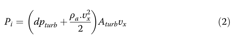
where dPturbrepresents the turbine duct differential pressure [Pa], ρais the density of air [kg.m−3], Aturbrepresents the cross-sectional area of the turbine duct [m2],and νxis the speed of airflow [m.s−1].
In order to generate and implement accurate ocean water waves in Matlab/Simulink, many techniques for regular waves have been proposed in multiple applications of wave-particle kinematics corresponding to the varying complexity of ocean waves [80, 81].Several water wave theories have been presented to examine the characteristics of ocean water waves [82], including wave theory, Stokes second-order waves theory, high order theories, finite-amplitude wave theory, stream, solitary,and cnoidal wave theories.The velocity of an airflow crossing through the turbine duct can be implemented by studying Airy wave theory.A wide range of wave climate spectra, OWC device dimensions, parameters, and prototypes are reported [83].The velocity of airflow at the passage of the turbine can be expressed as:
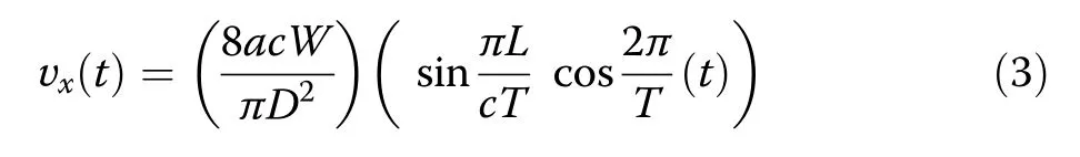
where T is wave period [sec], L is the length [m], and W is the width of the OWC chamber.a is the ocean wave amplitude [m], D is the Wells turbine duct diameter,and c is the regular propagation speed.
2.1.2 Modelling of Wells turbine
OWCs are categorized based on their shape, PTO units,and location requirements.The Wells turbine was first developed by Professor Alan Wells of Queen’s University of Belfast in the late 1970s [84].Note that the compressed air goes through a bi-directional turbine.Varieties of equations shown in (4) are used for modelling purposes [16, 85].

where Rturbis the Wells turbine mean radius [m], ltis the length of blade chord [m], ntis the number of turbine blades, kturbis a constant [kg..m−1], and φ is the turbine flow coefficient.ωturbis the ocean wave turbine angular speed [rad.s−1] and Tturbis the Wells turbine torque.A1and A2represent the constants obtained from mean optimum speed and pneumatic power of generator,respectively.Фtavgis the sorted OWC pressure under average time span,btis the height of turbine blade[m],and Caand Ctare the turbine power and torque coefficients, respectively.Pturbis the turbine power [W], Q is the flow rate[m3.s−1],and ƞturbis the turbine efficiency.
The OWC device converts wave energy by availing wave elevation to compress or decompress the available air in a chamber.The exhaling and inhaling air travels to and from space through a self-rectifying turbine, which drives an electric power generator.This characteristic of the Wells turbine is due to its specially designed symmetric blade figure, as shown in Fig.2.It operates on aerofoil theory and a lift over the aerofoil generates the Wells turbine rotation by producing an excellent tangential torque force outline[86].

Fig.2 Wells turbine concept and illustration of acting components on a turbine rotor blade.a Schematic representation of the Wells turbine.b Representation of aerodynamic forces
2.1.3 Modelling of permanent magnet synchronous generator
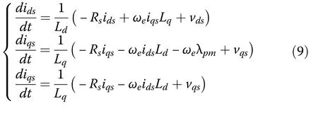
In this study, the PMSG speed is maintained at a constant level.The optimum way of modelling threephase PMSG is achieved by applying the Park transformation, in which the physical three-phase part is converted into an orthogonal two-axes d-q reference frame.The rotor position is set at 90°behind phase Aaxis, while at θr=0, the d-axis is in adjustment with the position of the permanent magnet rotor.Since the rotor rotates with the d-q frame of reference at the synchronous angular speed, the PMSG voltage equations under the d-q reference frame and stator flux can be expressed as [87]:
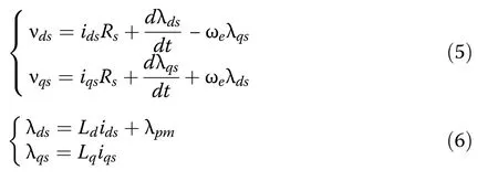
where Rsis the stator winding resistance, and Ldand Lqare the inductances in the d-q axes.ωeis the synchronous electrical speed frequency and λpmis the rotor magnet flux linkage from the permanent magnet.Also, Teis calculated as:
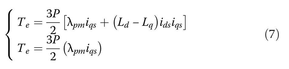
where P is the number of poles.For a surface-mounted PMSG, Ld= Lqso the equations for Tecan be rewritten as:
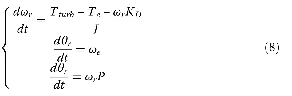
where ωris the mechanical rotor speed of the PMSG[rad.s−1] and KDis the damping coefficient [Nm.s.rad−1].In this modelling, the viscous friction coefficient and the total inertia are known, while in the real world, the designed and measured values may vary owing to manufacturing process variations and differences according to time.
3 Applied control strategies to the ocean energy conversion system
3.1 Machine side converter control
This section designs and simulates the FOC and robust adaptive control strategies.For the nominal PMSGbased Wells turbine, the measured angular and rotor mechanical speed is acquired for the MPPT scheme.The applied MSC control strategy controls flux and torque separately, and this is achieved by the FOC control strategy [88].
3.1.1 Space vector pulse width modulation technique
In order to enhance the usage of the three-leg, back-toback power converters, an efficient space vector pulse width modulation(SVPWM) technique is applied [89].
The space vector concept is shown in Fig.3.The reason for using this technique is to refine the system behavior by minimizing the potential harmonic contents,switching losses, and to achieve maximum DC bus voltage utilization.

Fig.3 Illustration of space vector concept
3.1.2 Implementation of maximum power point tracking scheme
The selected OWC device delivers an optimized power over a specific speed range.The obtained Tturbas expressed in (4) determines the applied force on the generator shaft [79].The optimum value changes according to the incident wave.Therefore, the torque and flow coefficient are linked to the Wells turbine rotational speed.Thus the pressure drop and rotor resistance are calculated so that the flow coefficient remains lower than 0.3.Hence,φmaxcan be expressed as:
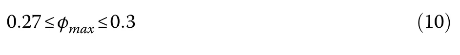
The purpose of the applied MPPT scheme is to operate the Wells turbine within this range.Maximum power is extracted from the OWC device.This is achieved by regulating the PMSG speed.If the Wells turbine generator speed is controlled at the reference speed, which accurately follows the incident angular speed, the Wells turbine can extract maximum power at multiple operating speeds.
3.1.3 Field oriented control strategy
In this subsection, a well-known FOC control strategy is implemented.It is a closed-loop control scheme where the stator current indirectly controls Te.Applying FOC strategy to the PMSG-based ocean energy conversion system offers a performance advantage.The main components of the simulated FOC control strategy are PMSG, power converter, speed and current controllers.The control is performed in the d-q reference frame,whileis obtained from the MPPT algorithm.PI controllers are implemented for current and speed regulation, while the inner current controller response must be quicker than the outer speed controller.In order to reduce Wells turbine generator control complexity, a constant angle control is accomplished by setting δ at 90°while the d-axis stator current is kept at zero.
As the stator q-axis current is relevant to the torque, it is called the torque producing current [90], while the permanent flux and torque angle are kept constant.Under FOC control, rotor position, DC-link voltage, and stator currents are considered as closed-loop feedback signals, as shown in Fig.4.is set at zero whileis generated by the speed PI controller.The d-q axis current regulators then obtain the converter voltage signals.For decoupling current control, ωeλqsis subtracted while ωeλdsis added, as shown in Fig.4.The required converter voltage is fed to the SVPWM scheme to generate the gate switching signals for the converter.
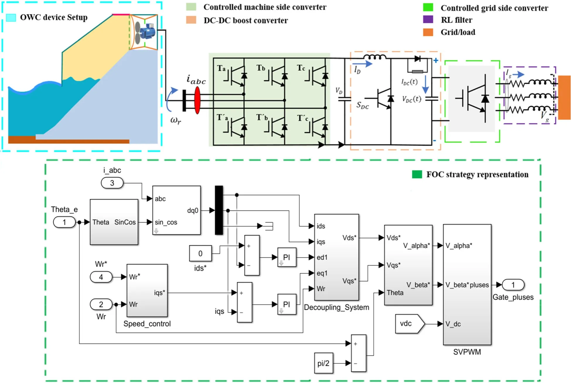
Fig.4 FOC control strategy in Matlab/Simulink
3.1.4 Adaptive back-stepping robust control design
In this subsection, an ABC algorithm is designed for MSC control of the OWC device based ocean energy conversion system.
Adaptive control is capable of providing a systematic method for designing controllers of unpredictable systems [91].This technique is a fusion of back-stepping control and adaptive laws.It can deliver better robustness to the system with known and unknown uncertainties.A non-linear system requires a highly efficient control strategy that can provide robust performance, balanced power, and corresponding stability.For this purpose, Lyapunov functions are calculated and implemented to improve system stability [92].
In the presented ocean energy conversion system, all subsystems contribute by providing a controlled signal for the next subsystem.Positive stable Lyapunov functions are introduced, and guarantee the desired speed tracking with efficient control of the PMSG.The desired speed control is accomplished by controlling iqswhile idsremains at zero.Thus, the Teis proportional to the current, while the stator magnetic flux linkage links to the PMSG rotor magnet linkage flux.Hence, from the relevant equations of PMSG expressed in(7)–(9),there is:
In order to keep the speed tracking error at zero, the components of relevant current are established by considering virtually controlled elements.These are used to drive the speed tracking error and its dynamics to zero in a finite time range.The time derivative of ωrerror and its dynamics are calculated as:

Defining the Lyapunov candidate function as:

the derivate of Lyapunov is obtained as:
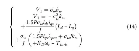
where kωrepresents the angular speed closed-loop feedback constant.
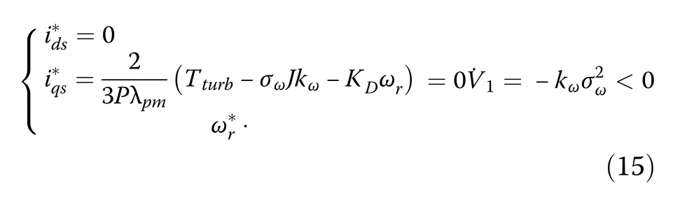
The validity of Lyapunov functions for the stator reference currents are represented as:
To provide the reference stator voltages based on the adaptive back-stepping calculation, the virtual input stator currents are considered.Therefore, current tracking errors can be expressed as:
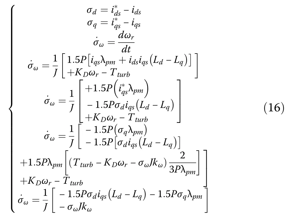
After further solving(16), a new set of equations is obtained as:

After further solving (17), it yieldsas:

For the evaluation of controlled voltages, a second Lyapunov function is calculated using (16)–(18).Error signals of the rotational speed tracking and stator current components are also considered.The Lyapunov functions can be expressed as:
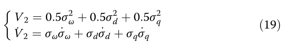
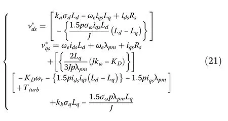
Substituting the various variables in (19), a new equation is obtained, as shown in (20).The constants (ka,kb)must contain positive values to ensure the stability of the MSC control system.

The Lyapunov function derivatives will become negative after inserting the voltage references.Hence, the obtained set of reference equations can be expressed as (21) while the applied adaptive control is shown in Fig.5.

Fig.5 Adaptive control strategy in Matlab/Simulink
3.2 Grid side converter control
The grid side converter (GSC) control strategy, as schematically shown in Fig.6, is implemented to handle grid synchronization, DC-link voltage, and active and reactive power.The core purpose of this control strategy is to deliver active power generated by the ocean energy conversion system to the grid.The internal loop controls the grid side current while the external loops control the DC-link voltage and reactive power [93].The DC-link voltage controller generates the reference current for the daxis.
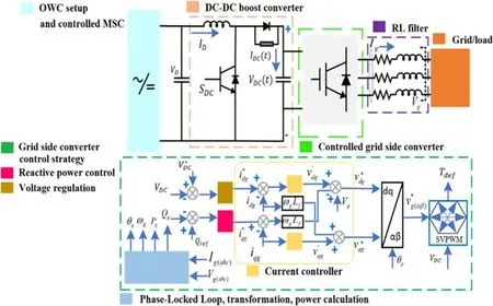
Fig.6 Schematic of GSC control strategy
The reference q-axis current is kept at zero.The d-q control scheme provides effective control using PI controllers, while active and reactive power control is obtained using the relevant concepts in [94].The SVPWM scheme is also used for GSC.The relevant set of equations are:
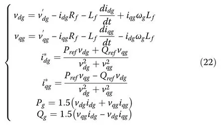
where Prefand Qrefrepresent the GSC active and reactive power references, respectively.Rfand Lfare the filter inductance and resistance, respectively, while ωgis the grid angular frequency.can be taken aswhile active and reactive power at vqg=0 and vdg=|V|reference frame are expressed in (23).
4 Inclusion of energy storage scheme
A scheme of a DC-DC boost converter connected to a battery bank is installed at the DC-link of the back-to-back power converter of the considered ocean energy conversion system.Battery storage system (BSS) enhances the reliability of the power system[95].The BSS can either perform as a load or a source[96].This scheme handles the low power situation caused by potential speed variations.For this reason, the DC-link voltage is kept at a constant level by trading a certain amount of power from the battery.
To keep the DC-link voltage at a constant level, the battery bank can perform charging or discharging according to a switching signal.The initial charging state is taken as 50–55%.The corresponding VDCis compared with the referenceand then the PI controller-based error signal is passed to generate the duty cycle for the insulated-gate bipolar transistor (IGBT) switches.The primary purpose of using a DC-DC boost converter is to raise the input voltage to a constant voltage level.The applied scheme is shown in Fig.7.

Fig.7 Scheme of DC-link optimization
5 Results and discussions
In this section, the results of the standalone PMSGbased ocean energy conversion system are examined,while the parameters and operating conditions are shown in the Appendix in Table 4.The waveforms are obtained from the FOC and adaptive control strategies.From (23), the turbine torque coefficient curve values and Cacan be estimated as [97]:
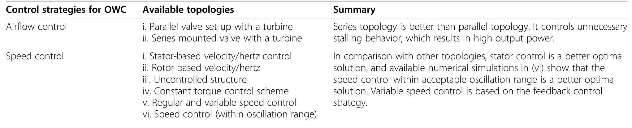
Table 1 Recently developed control strategies for the OWC device
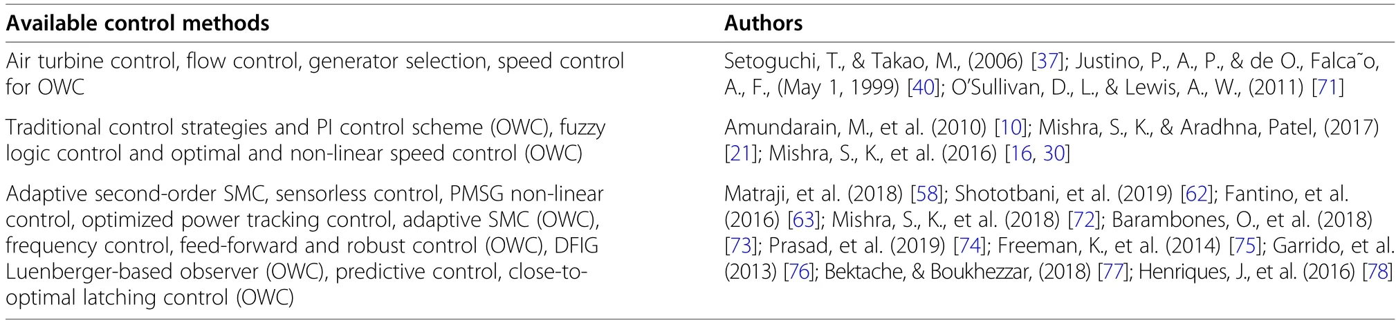
Table 2 Various control methods for renewable energy systems
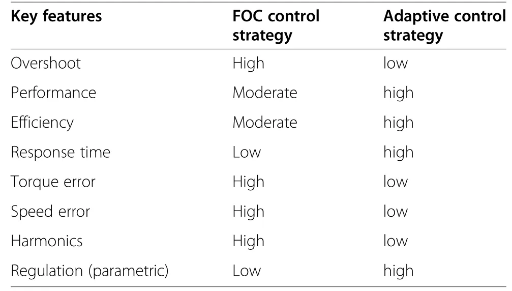
Table 3 Critical points of the applied control strategies

The generator section is mainly formed by the OWC device, including the Wells turbine, which is coupled with the PMSG.In the modelled OWC device, the flow rate is kept under a level of 120 and is implemented by inserting a steady pressure drop of |4000 sin(0.314t)| Pa acting as input as shown in Fig.8.
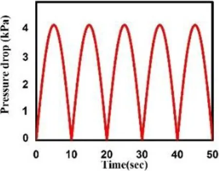
Fig.8 OWC chamber pressure drop
When the oscillations are higher than the Wells turbine torque, which is 0.3 in the simulated system, the power produced remains limited to the Wells turbine threshold value.The obtained mechanical power from the incident waves can be increased by keeping the flow coefficient below the required threshold value.The power and torque coefficients for the Wells turbine are shown in Fig.9(a) and (b), respectively, while the flow coefficient, which helps to generate enough torque from the OWC device setup, is shown in Fig.10(a).The OWC device can deliver a reasonable flow rate as shown in Fig.10(b).
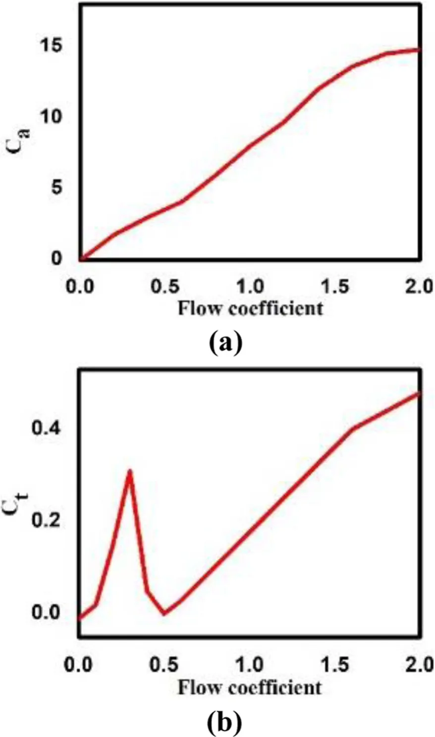
Fig.9 Characteristics of Wells turbine.a Power coefficient.b Torque versus flow coefficient
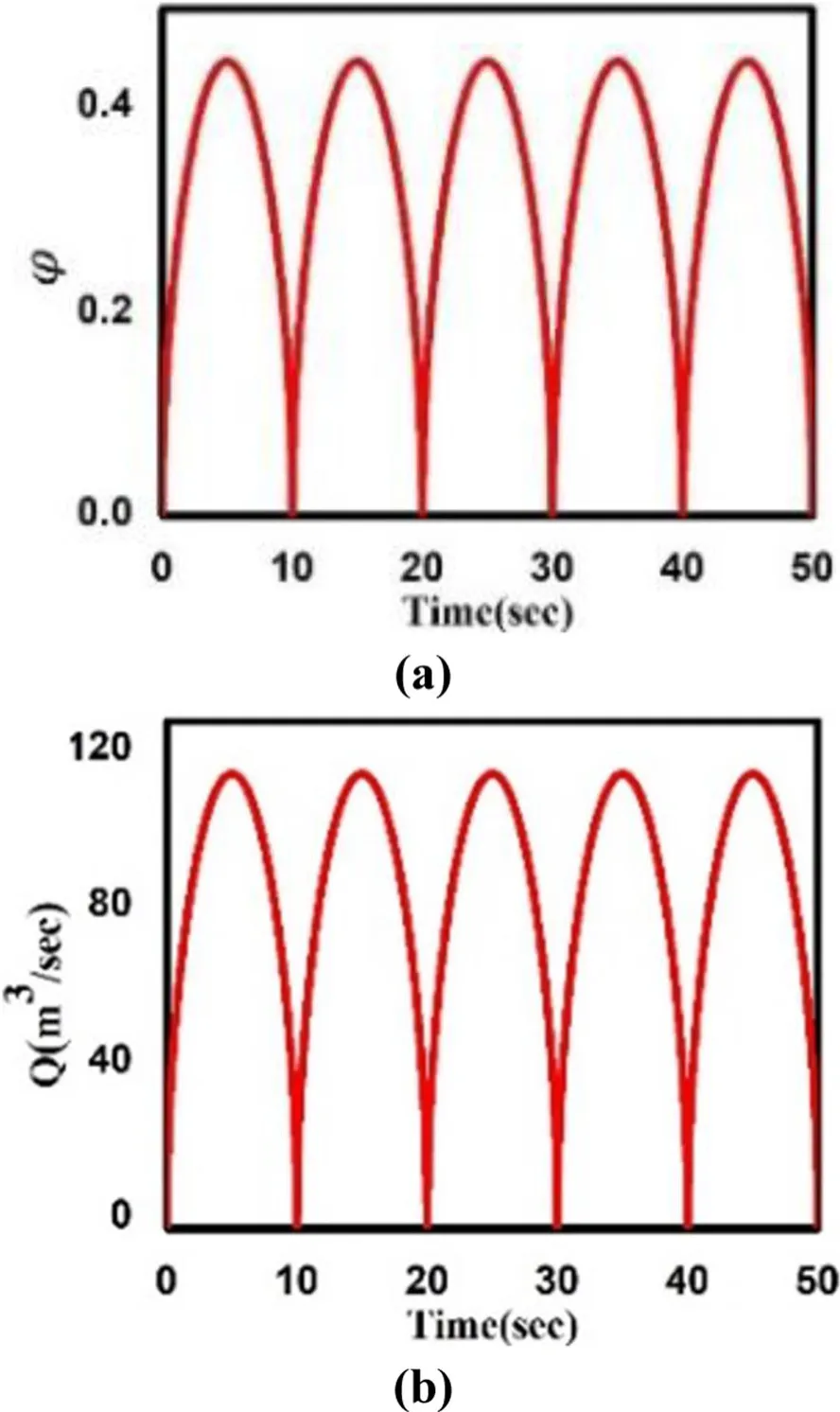
Fig.10 Attributes of the modelled OWC chamber.a) Flow coefficient.b)Flow rate
Also, the applied FOC control strategy provides the generator Tewith a slightly slower response than the adaptive control strategy, as shown in Fig.11(a) and(b).Rotational speed limits the efficiency of the power generation system because of the Wells turbine stalling behavior, as shown in Fig.11(c).The proposed electrical control of the PMSG-based wave generation system correctly responds to the entrance pressure drop, which results in a reference speed change under the MPPT strategy.It is responsible for driving the power generation system by providing enough rotational speed from the turbine generator shaft.The generated machine side current remains within the desired range as shown in Fig.11(c), while the current delivered to the grid side is shown in Fig.11(d).The system achieves good quality voltage,electrical current, and power output.

Fig.11 Torques and adaptive control-based outputs.a)Te based on FOC strategy.b)Te based on the adaptive control strategy.c)Machine side current output.d)Grid side current output
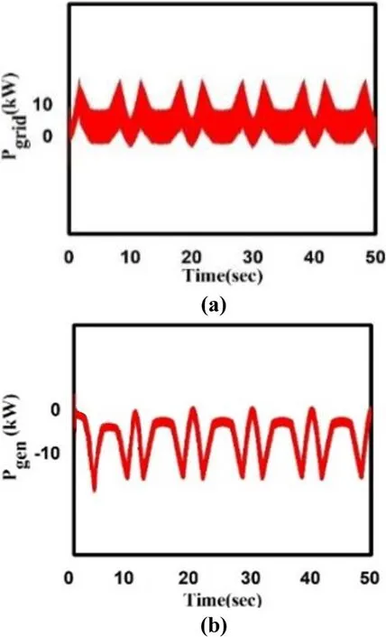
Fig.12 Power outputs.a)Adaptive control-based grid side power.b) FOC-based machine side power
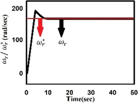
Fig.13 FOC control-based speed tracking
The Wells turbine effectively transfers stable power,as shown in Fig.12(a) and (b).The actual generator speed under FOC and adaptive control strategy are shown in Figs.13 and 14.Under the typical wave scenario, both control strategies reasonably follow the speed reference for maximum power output.In the FOC strategy, the system starts full reference speed tracking in 9 s, while under the adaptive control strategy, the system starts tracking the reference speed at around 1.6 s.

Fig.14 Adaptive control-based speed tracking
It clearly shows the superiority of adaptive control over FOC control strategy for the wave power generation system.Adaptive control of the ocean energy conversion system with minimum delay and less overshoot has been verified, as shown in Figs.13 and 14.
Adaptive control enhances system stability and robustness by reducing potential errors from the designed control signals as evidenced from Figs.15 and 16, verifying its improved performance and dominance over FOC control.The speed tracking error is 0.4% in FOC and 0.36% in adaptive control as shown in Fig.15(a) and (b).Similarly, torque and percentage errors for FOC and adaptive control strategies are shown in Fig.16(a) and (b),respectively.
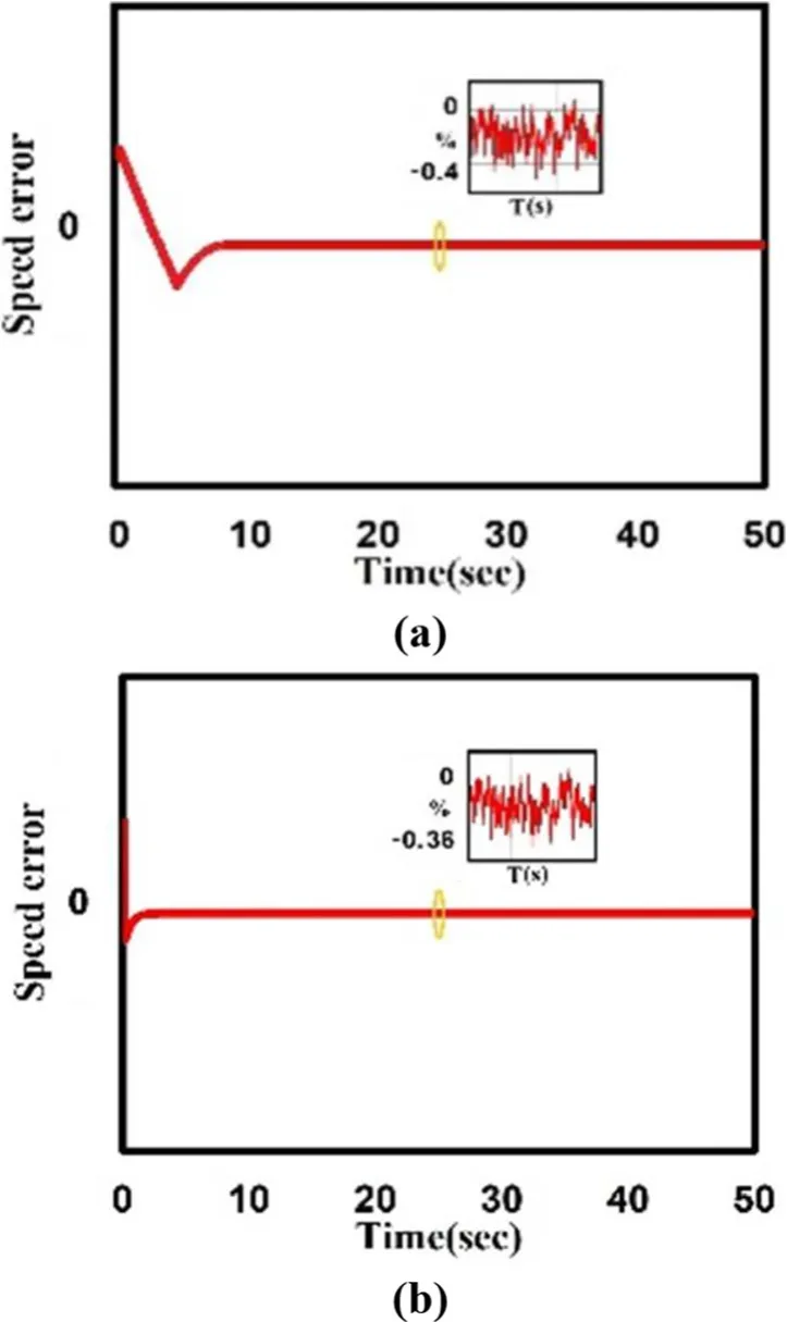
Fig.15 Speed tracking error.a FOC-based error.b Adaptive control-based error
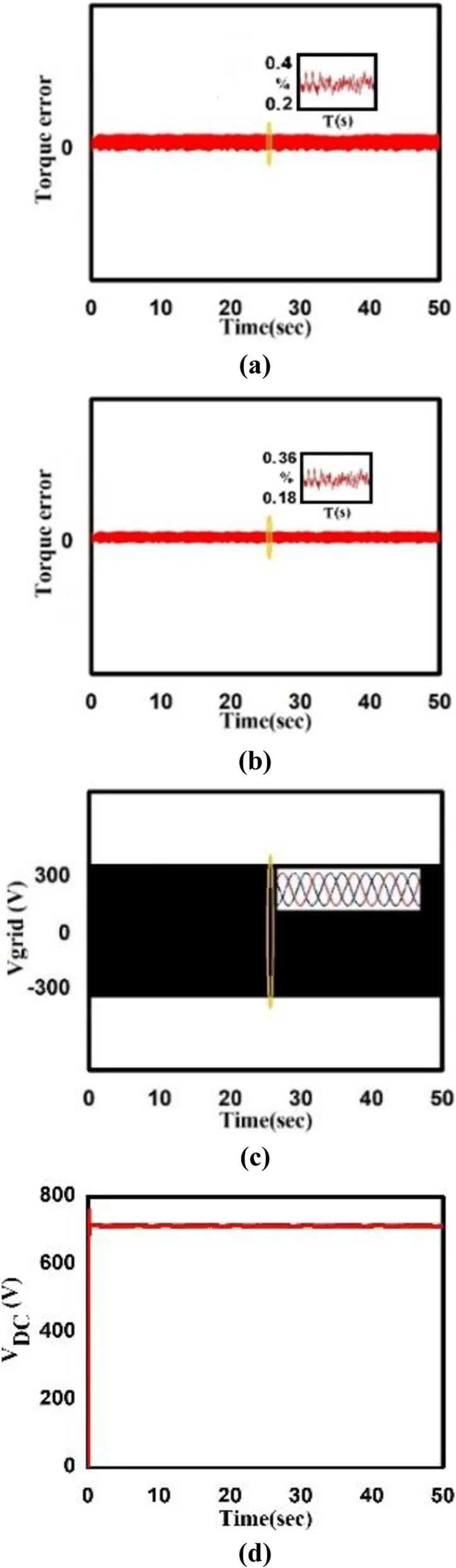
Fig.16 Torque error and power system voltages.a FOCbased torque error.b Adaptive control-based torque error.c Stable grid side voltage.d Optimized DC-link voltage
Figure 16(d) shows the DC-link voltage with the adaptive control under low fluctuations by connecting with an optimized energy storage scheme.The simulation results validate the optimal electrical control for the PMSG-based ocean energy conversion system using the adaptive back-stepping control.The results also support the correct application of the Lyapunov stability technique.It can ensure improved performance under parametric variations and speed changes.The Wells turbine generator operates in high efficiency, while ensuring stable decoupling control.The proposed adaptive control design can offer a better robust response and durable power with lower percentage errors than the traditional FOC.The scope of this research work can be enhanced by introducing more potential uncertainties,e.g., machine stator resistance, irregular wave, and speed conditions.Table 3 summarizes key points of Section 5.

Table 4 The parameters and operating conditions
6 Conclusions
The research has shown that the PMSG-based ocean energy conversion system can achieve better performance by implementing a robust adaptive control strategy followed by the Lyapunov method.Highspeed tracking performance is well assured by implementing an optimal solution, which shows the dominance of adaptive control over FOC control.The simulation results verify that the applied non-linear back-stepping control algorithm can deliver high dynamic and steady-state performance with minimum percentage errors for the OWC device-based power generation system.The inclusion of an energy storage system can facilitate the handling of a low power situation.Maximum power is also achieved using the SVPWM technique, generating less harmonic distortion in output voltage and current waveforms, and thus improving the power quality delivered to the electrical grid.
1 Appendix
Abbreviations
Pi:Incident power; Pgen: Generated power; Iabc: Generated current; Pgrid: Grid power; Igrid:Grid current;Vgrid: Grid voltage; ka, kb, kω: Control parameters;ids,iqs: d-q axes of the stator current; λds, ,λqs:d-q axes of the stator flux linkage; σω: Speed tracking error;: Reference stator voltages;d-q axis stator reference currents; p: Laplace operator; δ:Torque angle;: Reference speed; Vrms_ref:Phase voltage reference; φmax: Maximum flow coefficient;: Derivative of the current tracking errors;Te: Electromagnetic torque
Acknowledgements
This work is supported by National Natural Science Foundation of China(51477098).
Authors’ contributions
Muhammad Noman performed the study of the algorithm, verified the simulation and draft the manuscript.Guojie Li,Keyou Wang and Bei Han engaged in modifying the paper and submitted it to the PCMP.All authors read and approved the final manuscripts.
Funding
This work is supported by National Natural Science Foundation of China(51477098).
Availability of data and materials
Not Applicable.
Competing interests
No competing interests.
杂志排行

Protection and Control of Modern Power Systems的其它文章
- A comprehensive review of DC fault protection methods in HVDC transmission systems
- Application of a simplified Grey Wolf optimization technique for adaptive fuzzy PID controller design for frequency regulation of a distributed power generation system
- A critical review of the integration of renewable energy sources with various technologies
- Operational optimization of a building-level integrated energy system considering additional potential benefits of energy storage
- An integrated multi-energy flow calculation method for electricity-gas-thermal integrated energy systems
- Sliding mode controller design for frequency regulation in an interconnected power system