Energy and flux measurements of laserinduced silver plasma ions by using Faraday cup
2021-08-05MuhammadUsmanAslamBHATTIShaziaBASHIRAsmaHAYATKhaliqMAHMOODRanaAYUBMubashirJAVEDandMuhammadShahzadKHAN
Muhammad Usman Aslam BHATTI, Shazia BASHIR, Asma HAYAT,Khaliq MAHMOOD, Rana AYUB, Mubashir JAVED and Muhammad Shahzad KHAN
Centre for Advanced Studies in Physics (CASP), GC University, Lahore 54000, Pakistan
Abstract Silver (Ag) plasma has been generated by employing Nd:YAG laser (532 nm, 6 ns) laser irradiation.The energy and flux of ions have been evaluated by using Faraday cup (FC) using time of flight(TOF)measurements.The dual peak signals of fast and slow Ag plasma ions have been identified.Both energy and flux of fast and slow ions tend to increase with increasing irradiance from 7 GW cm−2 to 17.9 GW cm−2 at all distances of FC from the target surface.Similarly a decreasing trend of energies and flux of ions has been observed with increasing distance of FC from the target.The maximum value of flux of the fast component is 21.2×1010 cm−2, whereas for slow ions the maximum energy and flux values are 8.8 keV,8.2×1012 cm−2 respectively.For the analysis of plume expansion dynamics, the angular distribution of ion flux measurement has also been performed.The overall analysis of both spatial and angular distributions of Ag ions revealed that the maximum flux of Ag plasma ions has been observed at an optimal angle of ~15°.In order to confirm the ion acceleration by ambipolar field,the self-generated electric field(SGEF)measurements have also been performed by electric probe;these SGEF measurements tend to increase by increasing laser irradiance.The maximum value of 232 V m−1 has been obtained at a maximum laser irradiance of 17.9 GW cm−2.
Keywords:laser ablation, laser-induced plasma ions,Faraday cup,time of flight measurements,self-generated electric field, angular distribution
1.Introduction
Laser-induced plasma (LIP) generation is one of the popular and promising techniques that has been widely used in different fields of science and technology e.g.material processing, medicine and industrial applications [1].LIP is one of the best sources of electrons,ions and x-rays[2].High-energy ions can be used effectively in material processing [3], ion implantation [4], surface modification [5] and thin-film deposition[6].The laser-induced ion-treated surface provides a great control towards the attainment of required material after its physical and chemical alterations for particular applications.However, for the achievement of required modification,the specific energy and flux of ions are required.A large number of physical parameters are responsible for influencing the energy and flux of LIP ions, and laser irradiance is one of the most important factors [7].
There are various techniques which are being widely used for characterization of plasma such as laser-induced breakdown spectroscopy (LIBS) [8], Langmuir probe [9],time of flight mass spectroscopy (TOFMS) [10], electric and magnetic probe measurements [11] and Faraday cup (FC).Among all of these,FC is one of the simplest techniques[12]used for the measurements of energy and flux of ions and electrons.Usually the TOF method has been employed for the evaluation of kinetic energy(K.E)of ejected species of lasergenerated plasmas [13].Elsiedet al[14] have studied the dynamics of LIP ions of various low and highZmetals i.e.aluminum(Al),iron(Fe),cobalt(Co),molybdenum(Mo)and tin(Sn).They have evaluated metallic ion velocity as well as flux.They confirmed that the heavy metallic plasma ions showed multiple peak behavior in their TOF profiles.Such multiple peaks were not observed in the case of lighter metallic plasma ions.They have discussed the production of a double layer with the production of energetic prompt electrons.Haideret al[15]have characterized LIP of Al by using the TOF technique.The ions of laser-induced Al plasma were collected and analyzed by a FC ion collector.They observed the existence of double layer potential at the plasma vacuum interface and concluded that the plasma ions were accelerated according to their different charge states.Laskaet al[16]have performed the angular distribution of ions for different target materials and used laser intensities ranging from 1010–1017W cm−2.They have confirmed that at low intensities of laser, the current always has peak values along the normal direction of the target surface.However, at higher intensity values, the deviation of peak value from the target normal direction occurs.Due to this deviation, the maximum current values are obtained at the off-target normal axis.Many research groups have investigated flux and energy by using FC.Faridet al[7] experimentally studied the ion emission dynamics of LIP of various metals and non-metals and evaluated the K.E of slower ions (~10 keV or 40 keV).Torrisiet al[17] reported tantalum ion energy ranging from 500 eV to 1.28 keV by employing the ion collector technique.Our group has recently measured the energy and density of laser-generated silicon (Si) and germanium (Ge) plasma ions by using the FC technique[18].The energy ranges evaluated for laser-generated Si and Ge plasma slow ions are in the range of 156 to 166 eV and 108 to 124 eV, respectively.Meanwhile,the evaluated ion density range of laser-generated Si plasma ions is from 4.9×1020cm−3to 5.62×1020cm−3, and that for Ge plasma ions is from 11×1020cm−3to 12×1020cm−3.
Our preference for the selection of Ag as a target material is due to its high electrical conductivity and best optical properties [19].The LIP parameters of Ag are useful in various technological applications, such as nanoparticle generation, cluster production, contacts of low-voltage switching devices and as metal films[19,20].In the present work,a Nd:YAG laser has been used as an irradiation source in order to generate Ag plasma ions for the measurements of energy and flux.For this purpose,the FC plasma diagnostic technique has been used.Various parameters have been varied to study their effect on measurements of energy and flux of laser-induced Ag plasma ions including laser irradiance, distance of FC with respect to target surface,and angle of FC with respect to the normal direction of the target surface.Different combinations of the above parameters can provide the opportunity to obtain the best optimal conditions where maximum flux and energy of Ag plasma ions can be achieved.In order to justify the ions acceleration due to the ambipolar field(double-layer effect), the self-generated electric field (SGEF)measurements has also been performed for increasing values of laser irradiance.In the future, this study could be of significant help in different applications of material processing by laser-induced Ag plasma ions, such as ion implantation,thin-film deposition, and nano-structuring of materials.
2.Experimental details
In order to investigate energy and flux of the laser-induced Ag plasma ions, Ag samples were prepared for experimentation.Ag (99.9%) samples with dimensions of 3×3×0.5 cm3were selected as the target material.Samples were ground by using silicon carbide papers of different grades.After obtaining a smooth surface, the samples were ultrasonically cleaned in acetone for 20–30 min to remove all the contaminations.These samples were mounted on a sample holder of 4.5 cm diameter which was connected by a direct current(DC) motor controlled by a DC power supply to rotate the sample continuously for each laser pulse.
Figure 1 represents the schematic of the whole experimental set up used for energy and flux measurements of laser-generated Ag plasma ions.A Nd:YAG laser system with second harmonic of wavelength of 532 nm and pulse duration of 6 ns (Quantel 981C) was used as an irradiation source to generate Ag plasma.The laser beam, after passing through a focusing lens of focal length 50 cm, hits the Ag target at an angle of 45° with respect to the target surface normal and generates the plasma.The plasma was detected,using FC as a detector.Ag targets were irradiated at eight irradiances,7,8.6,10.1, 11.7, 13.2, 14.8, 16.4 and 17.9 GW cm−2, corresponding to the laser pulsed energies of 90,110,130,150,170,190, 210 and 230 mJ with optical focused spot size of 522 μm, which was measured by scanning electron microscopy (SEM) analysis of the ablated crater.The corresponding irradiance values corresponding to various laser pulsed energies are listed in table 1.
An assembly of six FCs was designed and fabricated for measurements of energy and flux of Ag plasma ions.For this purpose, each FC of diameter 1.5 cm and area of 3.79 cm2was selected as a detector.The assembly of the FCs was designed in two parts.In the first part of the assembly, two cups FC1and FC6were placed in the direction normal to the target surface.FC1corresponds to the first FC that was placed nearer to the target surface at a distance of 5 cm, and FC6is the second FC that was placed at a 5 cm distance from FC1(10 cm from the target) but was slightly uplifted so that it showed the ability to collect laser-induced Ag ions after a particular flight time.This dual-cup assembly was used for TOF measurements of Ag plasma ions between FC1and FC6for the evaluation of their K.E.The second part of the assembly was designed in order to perform an angular distribution of laser-induced Ag plasma ions.It is an angular arc which consists of 5 cups FC1–FC5which have been placed at angles of 0°, 15°, 30°, 45° and 60° with respect to the target surface normal.The FC assembly was initially placed at the distance of 5 cm, which was then increased step by step to 6 cm, 7 cm and 8 cm.In this arrangement it is possible to get data at 8 different distances with respect to the target surface for the spatial distribution of laser-generated Ag ions flux in the axial direction.All the FCs were negatively biased in order to collect ions by using a DC power supply (GPR-603,GW Instrument, Taiwan, China).
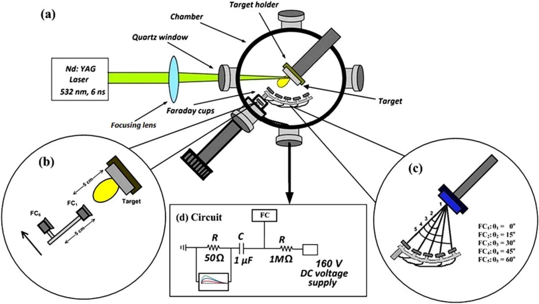
Figure 1.The schematic of the whole experimental set up for generation and detection of laser-generated Ag plasma ions by FC.(b)Arrangement of two cups (FC1 and FC6)placed at a distance of 5 cm from each other for evaluation of K.E of Ag plasma ions by TOF measurements.(c) Assembly of five FCs placed on the arc for angular distribution of Ag plasma ions (FC1 to FC5).(d) The electric circuit used to collect ions signal data from FCs.
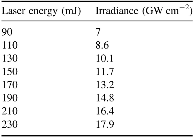
Table 1.The corresponding irradiances corresponding to various laser pulsed energies.
In order to perform SGEF measurements of laser-induced Ag plasma, a brass electric probe was designed and fabricated.This probe has a length of 38 cm,a diameter of 0.2 cm with a sharp tip of 0.08 cm diameter, and an area of 2.5×10⁻²cm2.This experiment was performed for five selected higher laser irradiances ranging from 11.7 GW cm−2to 17.9 GW cm−2.The probe was injected into the chamber by using a Teflon rod of length 35.5 cm and diameter 0.25 cm as an insulator casing of brass rod.The probe was placed at an angle of 45°and at a distance of 1 cm from the target surface.The schematic of complete experimental set up used for SGEF measurements is shown in figure 2.
All experiments were performed under high vacuum conditions in a stainless steel vacuum chamber, which was evacuated up to a base pressure of 10−7Torr by using a turbo molecular pump followed by a rotary vane pump.The appropriate circuits were used for FCs and electric probe measurements.The signals of Ag plasma ions either collected by FC or by electric probe were displayed on an oscilloscope(TDS 305B, Tektronix, USA).
3.Results and discussion
Figures 3(a) and (b) represent the typical TOF signals of laser-induced Ag plasma ions at minimum and maximum irradiances of(a)7 GW cm−2(b)17.9 GW cm−2respectively at eight different FC distances of 5, 6, 7, 8, 10, 11, 12 and 13 cm from the target surface.
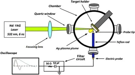
Figure 2.The schematic of experimental set up for the measurements of the self-generated electric field of laser-generated Ag plasma.
These signals show the decreasing trend of voltage amplitude of Ag ions by increasing FC distances from the target surface for both irradiances.The comparison of both figures 3(a)and(b)shows that the peak voltage is influenced by the laser irradiance, and is higher for higher irradiance.The values of voltage decreased with increasing distance due to free expansion of the plasma plume under vacuum conditions.Similarly higher irradiances are responsible for the generation of more charge species due to a higher ablation rate and enhanced energy deposition[21].Therefore,a higher amplitude of signals is detected at higher irradiances.The ion profile also reveals the phases of twin peak signals, representing fast and slow ions.The first peak corresponds to fast components (fast ions, protons) and the second peak to slow ions.This twin peak behavior in plasma is referred to the double-layer effect of plasma[7,14].Various research groups have reported the appearance of twin peak ion signals only for heavy metals [14].After the detailed study of these double structures, it is deduced that they are due to the formation of multiple components in plasma, such as fast and slow components.The appearance of these fast and slow components is due to different ablation processes, such as fast electronic processes and thermal ablation processes.Fast electronic processes generate fast components, whereas the thermal ablation processes are responsible for the generation of slow ions in laser-generated double-structured plasma [22].The fast ion emission is also attributed to the production of prompt electrons during laser matter interaction.The prompt electrons are basically produced when electrons leave the lattice without giving their energy to the lattice.During the expansion of plasma, the space charge effect is produced between these prompt electrons and ejected ions, which causes further acceleration of ions.It is more probable that prompt electrons are generated from high-Zmaterials [7]; thus, fast ion emission is also very much expected for high-Zmaterials.Further literature study suggests that the multiple peaks may also arise due to the presence of ions with difference of charge states of ions in the plasma plume [23].It has been observed that the ionic charge state is highly responsible for the increase in velocities.This increase in velocity of highly charged ions is due to experiencing the greater space charge effect during the initial phase of plasma expansion where electrons strive to overtake plasma ions.Thus, the ions with a greater charge state experience a greater increase in energy from doublelayer potential [24].Another factor that is responsible for the formation of a faster ion peak is the three-body recombination process of highly charged state ions.The ions with a greater charge state undergo the process of three-body recombination,and experience the increase in energy corresponding to velocity up to higher values [25].Due to the increase in velocities, the highly charged ions are concentrated in the leading part,and singly charged ions in the trailing part of the ion signal pulse [26].The higher difference between velocities causes separation between both ions into the appearance of two different peaks, i.e.fast and slow ion peaks.Both components of the plasma plume have different expansion geometries due to the difference of energies of fast ion and slow ion flux.The fast components of the plasma plume are more confined and squeezed,whereas the slow components of the plasma plume expand at wider angles [7].
In the current study the first peak is referred to as fast components, which is most probably due to the presence of fast ions with different charge states produced by different ablation processes.The protons may also contribute to the fast peak signal, even if the DUV or EUV light cannot be completely ignored that has been verified by putting the CaF2crystal in front of the expanding plume.The emission of protons by LIP is usually reported for high-intensity lasers [27].
Dual (twin) peaks for heavy metals have been reported by various research groups.Elsiedet al[14]have studied the dynamics of laser induced-plasma ions of various low and highZmetals i.e.Al, Fe, Co, Mo and Sn.They have evaluated metallic ion velocity as well as flux.They confirmed that the heavy metallic plasma ions showed multiple peak behavior in their TOF profiles.Such multiple peaks were not observed in the case of lighter metallic plasma ions.They attributed the generation of fast ions to the generation of energetic prompt electrons.The double peaks of ions are attributable to the double-layer generation of plasma,which is already confirmed by electric field measurement.Furthermore, Saquilayanet al[28] studied plasma ions by using a laser density of 10.4 GW cm−2and showed that the multiple peaks can also arrive due to the presence of differently charged ions in plasma.It is also observed that the dual peak signal strongly depends on the laser irradiance value that can be observed.The strength of both fast and slow ion signals has increased by increasing the laser irradiance value, which can also be seen in figure 3.The similar type of peaks was investigated by Faridet al[7] for heavy metals, and they referred to these peaks as slow and fast ion peaks.
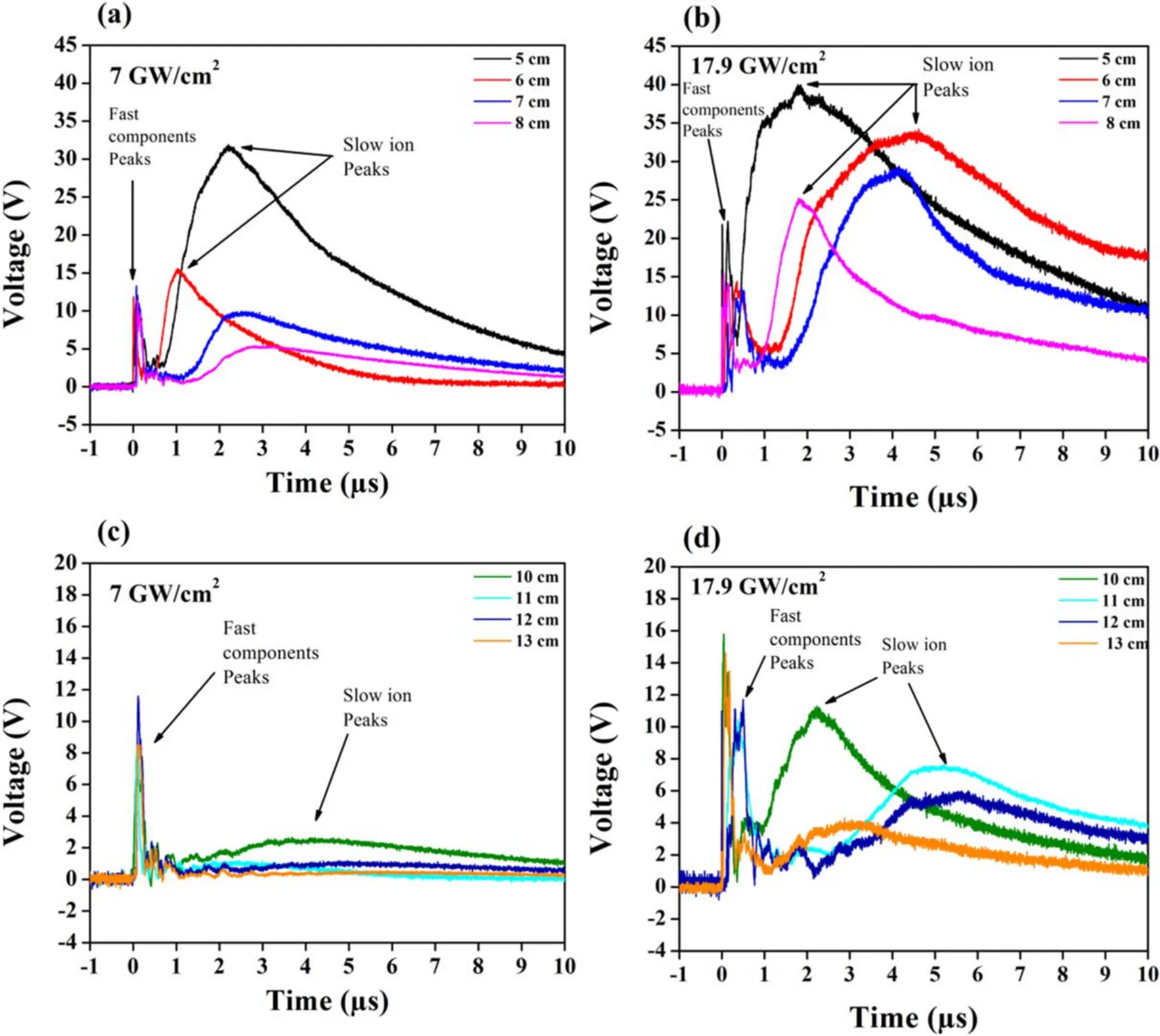
Figure 3.Typical TOF signals of laser-induced Ag plasma ions at minimum and maximum irradiances.(a) At minimum irradiance of 7 GW cm−2 for various FCs to target distances ranging from 5 cm to 8 cm.(b)At maximum irradiance of 17.9 GW cm−2 for various FCs to target distances ranging from 5 cm to 8 cm.(c)At minimum irradiance of 7 GW cm−2 for various FCs to target distances ranging from 10 cm to 13 cm.(e) At maximum irradiance of 17.9 GW cm−2 for various FCs to target distances ranging from 10 cm to 13 cm.
It is reported in the literature that there is the possibility of a proton peak during LIP formation [27, 29] that could be intermixed with the fast ion peak.The generation of protons during laser-generated plasmas has been reported at relatively high laser irradiance ranging from 1010to 1019W cm−2.These values of laser irradiance values are greater than our used value of irradiance, which is 109W cm−2.The possibility of the generation of protons cannot be completely ruled out.Torrisiet al[29]have investigated the ion acceleration in laser-generated Al plasma at an intensity of 1010to 1019W cm−2and detected proton energies in the range of 170 eV to 2.2 MeV with ion energies in the range of 920 keV to 20 MeV for thin Al targets of 1 mm to 4 μm thickness.They have used the Thomson Parabola Spectrometer to track theon-linelaser-generated Al plasmas,whereas a quadrupole mass analyzer was used to evaluate the mass-to-charge ratio as well as the charge state distribution of Al ions.
This ion acceleration is attributed to pondermotive forces,which give very high acceleration ion bunches.The deconvolution of ion peak analysis has provided the possible identification of protons.Torrisiet al[27] also reported that the ion energies are dependent upon Coulomb acceleration,plasma temperature and adiabatic gas expansion in the vacuum.These energies increase with increasing ion densities and laser irradiance.In the future, the identification of the proton peak will be helpful to rectify the possibility of hydrogen presence in materials as contamination by using state-of-the-art equipment like a mass quadrupole spectrometer (MQS) and TOFMS.
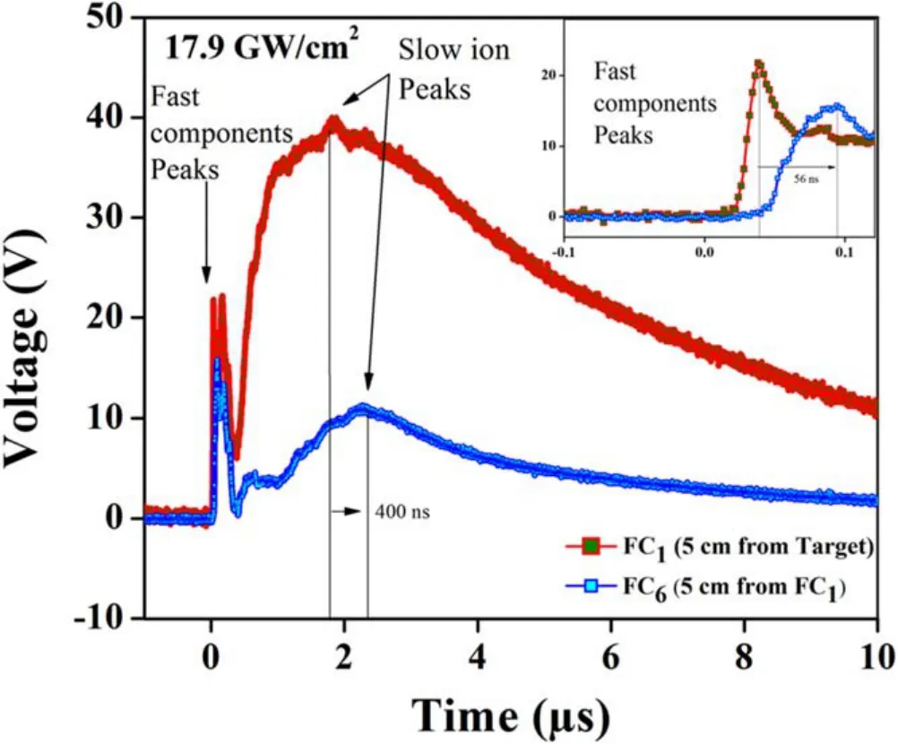
Figure 4.TOF signal of Ag plasma ions at laser irradiance of 17.9 GW cm−2 for K.E measurements.The delay between two signals of FC (FC1 placed at a distance of 5 cm from the target and FC6 placed at a distance cm from FC1)was measured.For slow ions,the delay between two signals is 400 ns, whereas for fast components,the delay between two signals is 56 ns;enlarged view is shown in the inset.
Figure 4 represents the TOF signal of Ag plasma ions at a laser irradiance of 17.9 GW cm−2for TOF measurements;the delay between two signals of FC(FC1placed at a distance of 5 cm from the target and FC6placed at a distance 5 cm from FC1and 10 cm from the target) is measured.For slow ions,the delay between two signals is 400 ns, whereas for the fast peak, the delay between two signals is 56 ns; the enlarged view is shown in the inset.
The first peaks for both FCs are very sharp and have a small delay of a few nanoseconds of 56 ns corresponding to the high-velocity particle peak, whereas second peaks corresponding to slow ions have a longer time delay of 400 ns.
3.1.Kinetic energy (K.E) measurements of Ag plasma ions
The energy of laser-induced Ag plasma ions,collected by FC,has been evaluated by using the following relation [30]:
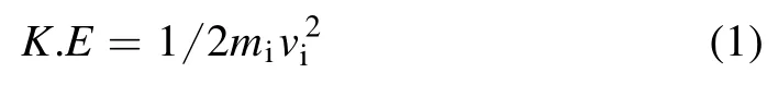
wheremiis the mass of Ag ions taken in kg which is=mi1.79×10−25kg(mass in amu×Avogadro numberAv)andviis the velocity of Ag plasma ions.The velocity of Ag plasma ions has been evaluated by using the following formula:
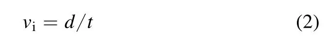
wheredis the distance between two FCs which has been kept constant at 5 cm andtis the time delay between two signals obtained from FC1and FC6.
Figures 5(a)and(b)show the variation of evaluated K.E of laser-induced Ag plasma ions as a function of laser irradiance at distances of 5, 6, 7 and 8 cm of FC from the target surface for both slow and fast components at an angle of 0°with respect to the target surface normal.It is observed from these graphs that as a function of irradiance for each distance,the trend of K.E of Ag plasma ions increases with increasing laser irradiance.This increasing trend is attributed to high ablation rates at higher irradiances.The maximum and minimum energies obtained for slow Ag ions are 8.8 keV and 0.16 keV, respectively.For the fast peak signal, there is possibility of the presence of fast ions along with protons;therefore,the energy for both possible components(fast ions,protons) is measured.
The maximum and minimum values of energy for the fast component of ions are 445 keV and 105 keV, respectively,whereas the minimum and maximum energy values for protons are 1 keV to 4.6 keV, corresponding to the delay measured between fast peaks by using two FCs.The comparison between slow and fast ions is the more important aspect regarding the present study.Therefore, only the fast ions(component)along with slow ion energy trends are displayed in figure 5.The possible proton energy in the fast peaks also shows similar trends to the fast ions.
This increasing trend is due to more laser energy deposition and enhanced collision efficiency of ejected species [3].The energy distribution of ions is highly dependent on the laser intensity.At higher intensities, the ions get accelerated by the fluence of pondermotive force at relativistic laser beam self-focusing [31], which leads to the non-linear process, resulting in the generation of highly energetic ions[32].By the comparison of both graphs it can be observed that the velocity of fast ions is very much higher than the energy of slow ions.Many factors are responsible for the generation of fast ions, such as the availability of prompt electrons, and the double-layer effect.The increased ion velocity along with the possibility of the presence of the highly charged state ions is responsible for the production of ions with greater energy values up to hundreds of keV.It is also observed from graphs that when the distance of first FC is varied from the minimum value, the K.E of slow ions decreases by increasing the distance of FCs from the target surface; therefore, the maximum values of K.E have been evaluated for a minimum distance of 5 cm.However, this effect has been observed to be quite random in the case of fast components.
There are various factors,e.g.pulse-to-pulse laser energy variation, biasing voltage fluctuation, UHV conditions, and target surface geometry, that may cause precision in the data measurement.All these factors are responsible for 2%–5%error in the measurements.Therefore, error bars of 5% have been placed.
3.2.Flux measurements of laser-generated Ag plasma ions
The average flux of ions is evaluated by taking the product of the peak current value and FWHM of voltage versus time signal.The flux of Ag ions is evaluated by using the following equation [33]:
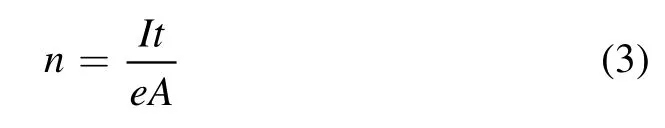
wheretis the time which is measured by taking FWHM of the ion signal[34],Iis the peak current of the ion signal which is calculated byI=V/R, whereVis the peak voltage of Ag plasma ions measured on the oscilloscope, andRis the resistance across which the voltage has been measured.eis the electronic charge andAis the area of FC which is 3.79 cm2.
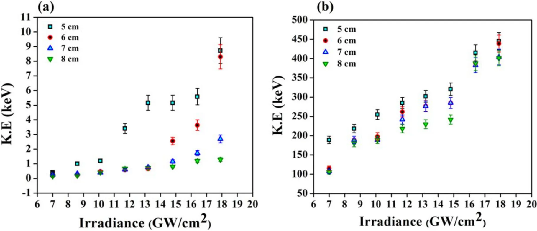
Figure 5.The variation of evaluated K.E of laser-induced Ag plasma ions as a function of laser irradiance at distances of 5,6,7 and 8 cm of FC from target surface for both (a) slow and (b) fast components.
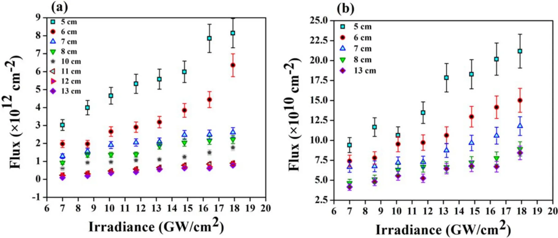
Figure 6.The variation in evaluated flux of Ag plasma ions as a function of laser irradiance at FC to target surface distance varying from 5 to 8 cm and 10 to 13 cm for both (a) slow and (b) fast components.
Figures 6(a)and(b)reveal the variation in evaluated flux of Ag plasma ions as a function of laser irradiance at FC to target surface distance varying from 5 to 8 cm and 10 to 13 cm for both slow and fast components.The variation of fast ions at a larger distance from 10 to 13 cm is minimum as compared to a relatively smaller distance; therefore, only 13 cm distance points are plotted in figure 6(b) to improve understanding of the graph.
As a function of irradiance for each distance, it is observed that the flux of Ag plasma ions increases by increasing irradiance.The maximum and minimum fluxes obtained for slow ions are 8.2×1012cm−2and 9.8×1010cm−2respectively.For fast components the maximum and minimum values of flux are 21.2×1010cm−2and 4.2×1010cm−2respectively.
It is also observed from figures 6(a)and(b)that values of Ag plasma ion flux decrease with increasing the distance of FC from the target.The flux values of fast components are lower than slow ions,because thermal processes are dominant in the case of ns laser [35].The plasma expands in a conical shape; therefore, the charge particles per unit area are higher for smaller distances of FC from the target surface, and this flux value decreases with increasing distance.
The increase of energy and flux value is attributed to a high ablation rate at higher irradiances[21].This leads to the enhancement of collisional frequencies of different ablated species (i.e.ions, electrons).The enhancement of ion collisions between each other and also with other ablated species in plasma causes an increase in the rate of ionization, which further increases the K.E and mass ablation rate [15].The irradiance value also increases the energy deposition rate,which increases the K.E and flux of ions [36].Another argument that could be helpful is the generation of lasersupported detonation (LSD) waves at lower irradiances,whereas laser-supported combustion (LSC) and laser-supported radiative (LSR) waves are generated at higher laser irradiances [18].The presence of these shockwaves enhances the flux and K.E of ejected species of plume due to energy coupling at higher irradiances [37].
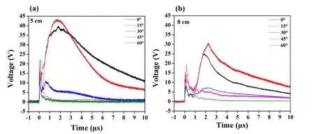
Figure 7.Typical TOF signals of Ag plasma ions at laser irradiance of 17.9 GW cm−2 at different angles of FC varying from 0°,15°,30°,45°and 60° with respect to target surface normal for FC to target surface distance of (a) 5 cm and (b) 8 cm.
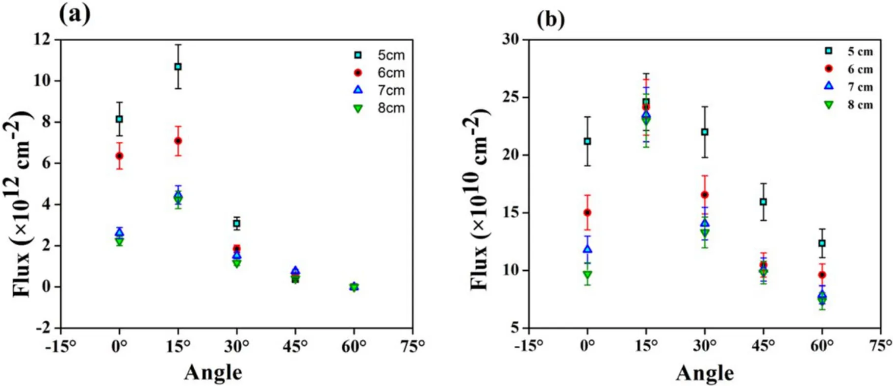
Figure 8.The variation in flux of laser-generated Ag plasma ions as a function of angle of FC with respect to target surface normal at distance varying from of 5, 6, 7 and 8 cm at fixed laser irradiance of 17.9 GW cm−2 for both (a) slow and (b) fast components.
3.3.Angular distribution of lasergenerated Ag plasma ions
Figures 7(a) and (b) show the typical TOF signals of Ag plasma ions at laser irradiance of 17.9 GW cm−2at different angles of FC varying from 0°, 15°, 30°, 45° and 60° with respect to the target surface normal for FC to target surface distance of 5 cm and 8 cm.It is clear from the graphs that the maximum intensity signals are obtained at an angle of 15°with respect to the target surface normal.
Figure 8 shows the variation in flux of laser generated Ag plasma ions as a function of angle of FC with respect to target surface normal at distance varying from of 5,6,7 and 8 cm at a fixed laser irradiance of 17.9 GW cm–2for both(a)slow and(b) fast components.After the detailed analysis of angular distribution of Ag plasma ions, it is observed that at first the value of flux increases by increasing the angle from 0°to 15°.A further increase in the angle causes the reduction of flux values, and minimum values are obtained at a maximum angle of 60° with respect to the target surface normal.The maximum flux value of Ag plasma in angular distribution for slow ions is 10.7×1012cm−2, and for fast components it is 24.6×1010cm−2.
The angular distribution of ions provides a great understanding toward the conical expansion of the Ag plasma plume.It is clear from literature study that the maximum flux has been measured for 0° [38] due to forward peaking of the plasma plume expansion [7].Several research groups have investigated plasma parameters by angular distribution and discussed the plume expansion dynamics[7,14].Interestingly in the current study, it has been seen that maximum flux is obtained on the FC which is placed at 15°angle with respect to the target surface normal.
The ions of the plasma attain acceleration according to theirm/zratio and the strength of the electric field.In the normal direction the electric field strength is weaker as compared to the off-normal direction, because the ions of plasma have the shortest distance from the electron layer in the off-normal direction and relatively larger distance in the normal direction.Therefore, the ions which are expanding in the off-normal direction can easily reach to the electron front,whereas the ions in the direction normal to the target take a longer time to reach the electron front.Due to the smaller width of the double layer at larger angles,it is much easier for ions to cross the double layer; thus, it is more probable for ions to get intense at larger angles [39].On the other hand,when the ions get a relatively larger pondermotive push in the target normal direction due to staying for a longer time in the double-layer region, it is highly probable that a large number of ions will go under the forward peaking condition.Therefore,the combination of both these phenomena is responsible for obtaining maximum flux at an angle other than 0°,but this angle cannot be very much larger.In the present study, the ions get acceleration in the presence of a strong self-generated electric field of plasma which is up to 232 V m−1for selected irradiance values, and maximum flux is observed at an angle of 15°.Konduet al[40] irradiated the Ag target to a nanosecond Nd:YAG laser with second harmonic.They have investigated that the Ag ion dense angle is ±(10°–15°), even for low irradiance values of 108W cm−2.
3.4.Self-generated electric field (SGEF) measurements of laser-generated Ag plasma ions
The detailed study also suggests that the laser-induced plasma ions also experience acceleration due to the generation of SGEF.This SGEF is most likely to be caused by the presence of double peaks that correspond to double-layer plasma.According to the electrostatic model [41],during laser matter interaction the electrons are heated through the inverse Bremsstrahlung (IB) process.This absorbed energy is transferred to the ions by a collisional process in the expanding plasma.The thermalization time of the electron-ion(10−10–10−11) is much smaller than the pulse duration of the laser [42]; thus, both ions and electrons achieve the thermal equilibrium in the early portion of the pulse.As the electrons are a lighter species than the ions in the plasma,they acquire a greater thermal velocity than the ions.This property helps the electrons to escape from the plasma, but the space charge effect is produced in between leading electrons and the ions,which are lagging behind.This effect prevents the complete escape of the electrons from the plasma[43].As the electrons become more confined at the leading edge of the plume, this separation of electrons and ions is followed by the formation of a self-electrostatic force between the leading electrons and ions which are lagging behind.This electrostatic force is proportional to the ion K.E and charge state[43].The study of ablation dynamics describes that the generation of an ambipolar electric field (double-layer effect) is another version of the electrostatic force which plays an important role in accelerating the laser-induced plasma ions[44].The literature study suggests that the acceleration gain by SGEF is responsible for the generation of high K.E ions [45].
In order to confirm the validity of double-layer plasma and acceleration of ions up to hundreds of keV range, the SGEF has also been measured by electric probe.Figure 9 shows the electric probe signals for the evaluation of SGEF of laser induced Ag plasma for five selected laser irradiances of(a) 11.7, (b) 13.2, (c) 14.8, (d) 16.4, and (e) 17.9 GW cm–2along with laser signal.Figures 10(a)–(e)show electric probe signals for the evaluation of SGEF of laser-induced Ag plasma for five selected laser irradiances of (a) 11.7 (b) 13.2(c) 14.8 (d) 16.4 and (e) 17.9 GW cm−2along with laser signal.The signals of the electric probe show the increasing trend of peak voltage with increasing laser irradiance.The electric field is calculated by using the following relation[46]:
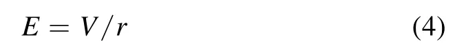
whereVis the peak voltage measured by electric probe andris the distance of the probe with respect to the target surface,which is kept constant at 1 cm.
The electric field signal is bipolar in nature.This type of signal is usually reported for the circuit for which theRCconstant time is less than the electric signal variation time[47].The bipolar nature of the electric field of laser-induced Zr plasma is explained on the basis of the quadrupole of the charges in the laser-induced plasma.One core is near to the target and the other one is far away.This dual-core plasma contains dipoles in opposite directions, and they carry their own electric field [48].The electric field signals are obtained within the laser pulse duration.It is shown that the nature of the electric field is in a differencing mode [44].The electric field can be calculated by using following relation [49]:
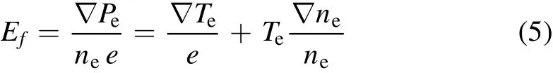
where ‘e’ is the charge on the electron, ‘∇Te’ is the temperature gradient and ‘∇ne’ is the density gradient.The SGEF strongly depends upon the temperature and density gradient term.Therefore, at different positions of plasma, the temperature and density gradients will be responsible for various values of the electric field.
The graph shows the variation of SGEF of laser-generated Ag plasma as a function of laser irradiance.The SGEF increases linearly from 170 V m−1to 232 V m−1with increasing laser irradiance from 11.7 GW cm−2to 17.9 GW cm−2.The increase in SGEF with increase in laser irradiance is attributed to the enhanced ablation rate and generation of more charge species.
4.Conclusions
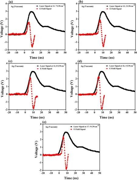
Figure 9.Electric probe signals for the evaluation of SGEF of laser-induced Ag plasma for five selected laser irradiances of(a)11.7,(b)13.2,(c) 14.8, (d) 16.4, and (e) 17.9 GW cm−2 along with laser signal.
The energy and flux of laser-induced Ag plasma ions have been investigated at eight different laser irradiances ranging from 7 GW cm−2to 17.9 GW cm−2by using FC as a plasma diagnostic technique.The dual peaks of laser-induced Ag ion signals have been identified.The first peak has a time delay in the range of few nanoseconds (ns) and is referred as the fast component peak, whereas the second peak with a time delay in the range of hundreds of nanoseconds(ns)to microseconds(μs) corresponds to the slow peak of Ag ions.It has been found that the energy and flux of laser-induced Ag ions strongly depend on several parameters, i.e.laser irradiances,FC distance from target, and the angle at which FC is placed with respect to the normal of the target surface.
By increasing irradiance, both the flux and energy of laser-induced Ag plasma ions increase.The distance of FC with respect to the target surface also affects the energy and flux values of the plasma ions.Both energy and flux tend to decrease by increasing FC distance from the target surface.The energy range for slow ions is 0.16 keV to 8.8 keV, the flux range of slow ions is 9.8×10¹⁰to 8.2×1012cm−2,and for fast components it is 4.2×10¹⁰to 21.2×1010cm−2.
For investigation of plume expansion dynamics, the angular distribution has also been performed at five different angles of 0°, 15°, 30°, 45° and 60°.The flux analysis of Ag plasma ions reveals that the maximum values of flux of Ag plasma ion are 10.7×1012cm−2for slow ions and 24.6×1010cm−2for fast components, which has been observed at an angle of 15° with respect to the normal of the target surface.
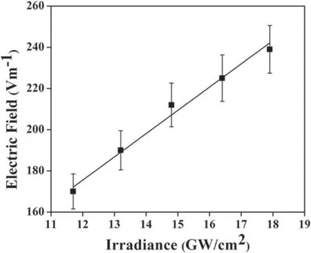
Figure 10.The variation of SGEF of laser-generated Ag plasma as a function of laser irradiance.
The electric field of laser-induced plasma has also been investigated to ensure the ion acceleration due to the presence of a double layer in the plasma.The electric field tends to increase linearly from 170 V m−1to 232 V m−1with increasing laser irradiance from 11.7 GW cm−2to 17.9 GW cm−2.
Laser-generated Ag plasma ions with maximum K.E and flux,along with the maximum value of SGEF,can be used as a source of high energy, high flux ions and electric field.These ions can be used for material processing and ion-beam doping.
杂志排行

Plasma Science and Technology的其它文章
- Experimental investigation on DBD plasma reforming hydrocarbon blends
- Research on active arc-ignition technology as a possible residual-energy-release strategy in electromagnetic rail launch
- Distinguish Fritillaria cirrhosa and non-Fritillaria cirrhosa using laser-induced breakdown spectroscopy
- On abnormal behaviors of ion beam extracted from electron cyclotron resonance ion thruster driven by rod antenna in cross magnetic field
- Research on quinoline degradation in drinking water by a large volume strong ionization dielectric barrier discharge reaction system
- Influence of air addition on surface modification of polyethylene terephthalate treated by an atmospheric pressure argon plasma brush